


KRAMER ELECTRONICS LTD.
USER MANUAL
MODEL:
F- 121UK
UXGA / Audio Line Transmitter
Mounting Box for Ackermann
UK
Modular Floor Boxes
P/N: 2900-300036 Rev 1

F-121UK – Contents i
Contents
1 Introduction 1
2 Getting Started 2
2.1 Achieving the Best Per formance 2
3 Overview 3
3.1 Shielded Twisted Pair (STP) / Unshielded Twisted Pair (UTP) 4
3.2 About the Power Connect™ Feature 4
3.3 DDC Support 5
3.4 Defining EDID 5
4 Defining the F-121UK 6
5 Installing the F-121UK 7
5.1 Installing a Kramer Insert 7
5.2 Connecting the Cables to the Rear Side of the F-121UK 7
5.3 Installing the F-121UK inside the Ackerm ann Floor Box 8
5.4 Connecting the Front Panel Ports 10
5.5 Wiring the 8-pin Terminal Block Line Output Connector 11
5.6 Wiring the CAT 5 LINE IN / LINE OUT RJ-45 Connectors 12
6 Technical Specifications 13
Figures
UFigure 1: The F-121UK UXGA / Audio Line Driver Mounting Box (with Brackets)U 3
UFigure 2: F-121UK Front Panel (without Brackets)U 6
UFigure 3: F-121UK Fitted in an Ackermann Floor BoxU 10
UFigure 4: Terminal Block PinoutsU 11
UFigure 5: CAT 5 PINOUTU 12

F-121UK - Introduction 1
1
1 Introduction
Welcome to Kramer Electronics! Since 1981, Kramer Electronics has been
providing a world of unique, creative, and affordable solutions to the vast range of
problems that confront the video, audio, presentation, and broadcasting
professional on a daily basis. In recent years, we have redesigned and upgraded
most of our line, making the best even better!
Our 1,000-plus different models now appear in 11 groups that are clearly defined
by function: GROUP 1: Distribution Amplifiers; GROUP 2: Switchers and Matrix
Switchers; GROUP 3: Control Systems; GROUP 4: Format/Standards Converters;
GROUP 5: Range Extenders and Repeaters; GROUP 6: Specialty AV Pr oducts;
GROUP 7: Scan Converters and Scalers; GROUP 8: Cables and Connectors;
GROUP 9: Room Connectivity; GROUP 10: Accessories and Rack Adapters;
GROUP 11: Sierra Products.
Congratulations on purchasing your Kramer F-121UK UXGA / Audio Line
Transmitter Mounting Box for Ackermann UK Modular Floor Boxes which is ideal
for:
• Presentation venues
• Multimedia applications
• Long range graphics distribution for schools, hospitals, security, and st ores
The package includes the following items:
• F-121UK
• Power adapter (12V DC) and this user manual

2 F-121UK - Getting Started
2 Getting Started
We recommend that you:
• Unpack the equipment carefully and save the original box and packaging
materials for possible future shipment
• Review the contents of this user manual
• Use Kramer high performance high resolution cables
Go to http://www.kramerelectronics.com t o check for up-to-date
user manuals, application programs, and to check if firmware
upgrades are available (where appropriate).
2.1 Achieving the Best Performance
To achieve the best performance:
• Use only good quality connection cables to avoid interference, deterioration
in signal quality due to poor matching, and elevated noise levels (often
associated with low quality cables)
• Avoid interference from neighboring electrical appliances that may adversely
influence signal quality
• Position your Kramer F-121UK away from moisture, excessive sunlight and
dust
Caution: No operator serviceable parts inside the unit
Warning:
Use only the Kramer Electronics input power wall
adapter that is provided with the unit
Warning:
Disconnect the power and unplug the unit from the wall
before installing
i
!
F-121UK - Overview 3
3
3 Overview
The F-121UK mounting box for Ackermann Cablelink Plus Modular floorboxes is a
twisted pair transmitter for computer graphics video signals up to UXGA and
unbalanced stereo audio. It converts the input signals into a twisted pair signal
that it transmits to a compatible twisted pair receiver (for example, the Kramer
TP-122N). The F-121UK includes one opening (covered by a blank panel) for a
single Kramer insert.
In particular, the F-121UK transmitter features:
• A transmission range of more than 300ft (more than 100m), and a 20kHz
audio bandwidth with an S/N ratio that exceeds 80dB on the same
transmission range
• The capability to store EDID when programmed by the Kramer FC-200 XGA
EDID Copier (the EDID of the display on the transmitter can be captured via
the FC-200)
• A resolution of up to UXGA
• The Kramer Power Connect™ feature
• A 12V DC power supply
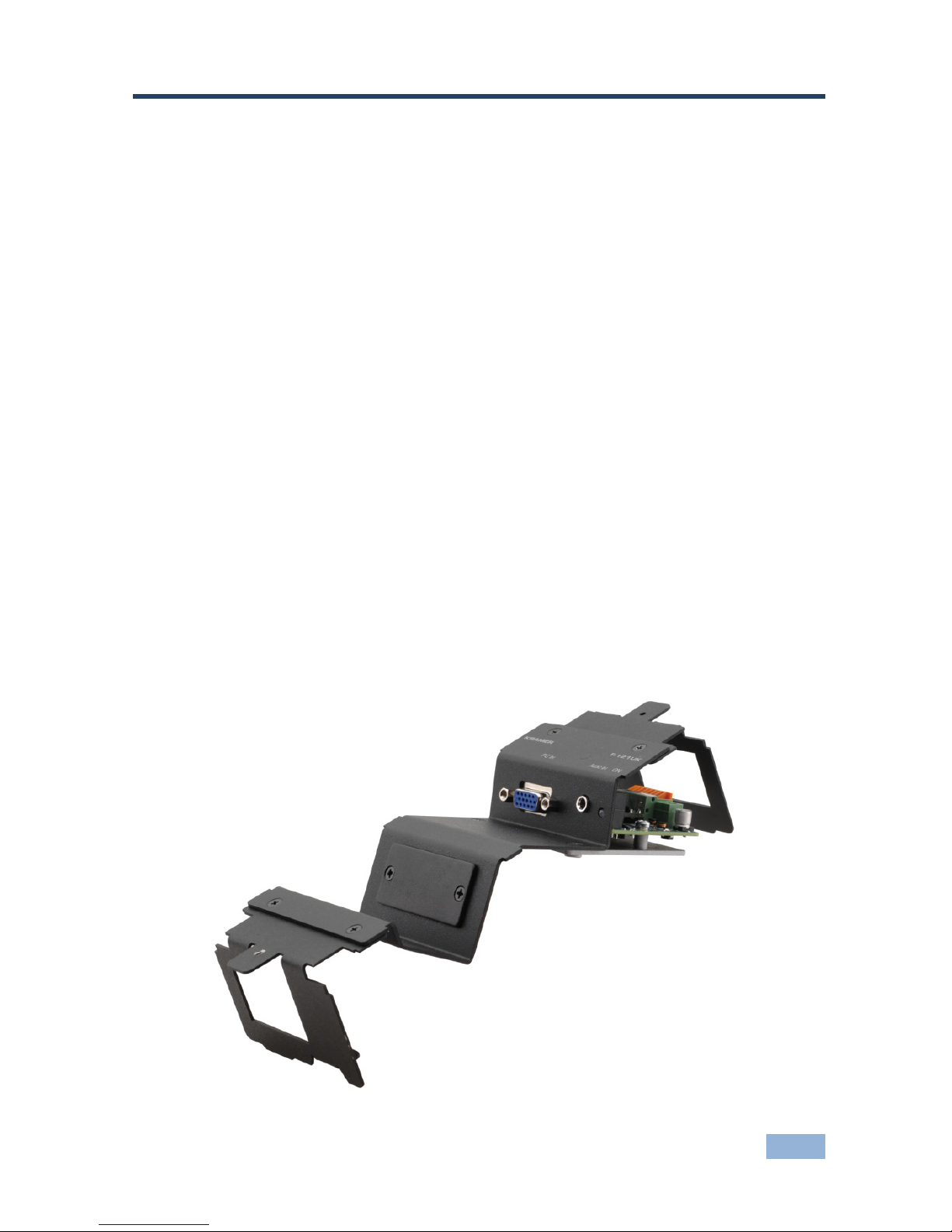
Figure 1: The F-121UK UXGA / Audio Line Driver Mounting Box (with Br ackets)

4 F-121UK - Overview
3.1 Shielded Twisted Pair (STP) / Unshielded Twisted Pair
(UTP)
We recommend that you use Shielded Twisted Pair (STP) cable. There are
different levels of STP cable available, and we advise you to use the best quality
STP cable that you can afford. Our non-skew-free cable, Kramer BC-STP is
intended for analog signals where skewing is not an issue. For cases where there
is skewing, our UTP skew-free cable, Kramer BC-XTP, may be used. Bear in
mind, though, that we advise using STP cables where possible, since the
compliance to electromagnetic interference was tested using those cables.
Although Unshielded Twisted Pair (UTP) cable might be preferred for long range
applications, the UTP cable should be installed far away from electric cables,
motors and so on, which are prone to create electrical interference.
However, since the use of UTP cable might cause inconformity to electromagnetic
standards, Kramer does not commit to meeting the standard with UTP cable.
3.2 About the Power Connect™ Feature
The Power Connect feature applies as long as the cable can carry power. This
feature is available when using STP cable and the distance does not exceed 50m
on standard CAT 5 cable. For longer distances, heavy gauge cable should be
used (CAT 5 cable is still suitable for the video/audio transmission, but not for
feeding the power at these distances). For units which are connected via RJ-45
connectors, make sure that the shield of the STP cable is connected to the metal
casing of the connectors on both ends of the cable. For units which are connected
via terminal block connectors, the shield of the STP cable must be connected to a
ground terminal on the units at both ends (use the ground terminal of the power
supply connection if necessary).
For a CAT 5 cable exceeding a distance of 50m, separate power supplies should
be connected to the transmitter and to the receiver simultaneously.

F-121UK - Overview 5
5
3.3 DDC Support
When establishing a VGA connection between a PC or laptop and a display device, a
set of parameters known as EDID is ex changed between them, which is carried over
the DDC channel. In some PC graphic cards and laptops, this information exchange is
essential for proper VGA OUT operation.
3.4 Defining EDID
The Extended Display Identification Data (EDID) is a data-structure provided by a
display, to describe its capabilities to a graphics card (that is connected to the
display’s source). The EDID enables the F-121UK to “know” what kind of monitor
is connected to the output. The EDID includes the manufacturer’s name, the
product type, the timing data supported by the display, the display size, luminance
data and (for digital displays only) the pixel mapping data.
EDID is defined by a standard published by the Video Electronics Standards
Association (VESA).

6 F-121UK - Defining the F-121UK
4 Defining the F-121UK
This section defines the F-121UK.
Figure 2: F-121UK F ront Panel (without Brackets)
# Feature Function
1 8-pin Terminal Block Line
Output Connector (located
inside the moun ting b ox )
Connect to the line in connector on the receiver (see
Section 5.52 )
Power Supply 2-pin Terminal
Block Connector
Connect to power s upply . Connect GND to G ND, +12V to
+12V
3 ON LED Lights red when re ceiv ing pow er, light s gree n w hen re ceiv ing
a signal fro m a v ideo sour ce
4 AUDIO IN 3.5mm mini
Connector
Connect to an un bal anced ste reo a udi o sour ce
5 Blank Insert Replace with a Kramer wall plate insert (see Section 5.16 )
Mounting Screws (2) Use to mount to f loor box via brackets (see Section 5.37 )
PC IN 15-pin HD F Connector Connect to the UXGA source

F-121UK - Installing the F-121UK 7
7
5 Installing the F-121UK
To install the F-121UK you have to install the inserts and the transmitter which is
connected via TP to a receiver.
To install the F-121UK, do the following:
• Install the Kramer in serts (see
Section 5.1
• Connect the cables to the rear side (see ) Section 5.2
• Install the F-121UK inside the Ackermann floor box (see ) Section 5.3
• Connect the front panel ports (see ) Section 5.4
• Connect the twisted pair cable to the receiver (for example, the Kramer
TP-122N)
)
5.1 Installing a Kramer Insert
To install a Kramer insert, do the following:
1. Unscrew the two screws holding the blank insert and remove it.
2. Place and align the required wall plate insert item over the opening.
3. Insert the two screws to fix the insert in place, and tighten them.
5.2 Connecting the Cables to the Rear Side of the F-121UK
To connect the rear side cables, do the following:
1. Run the cables through the Ackermann underfloor cable opening.
2. Connect the cables to the rear side of the inserts.
3. Connect the cables to the rear side of the F-121UK transmitter, that i s,
attach the:
Terminal block line output of the F-121UK to the pre-installed STP/UTP
wiring that connects to the TP receiver (for example, the Kramer
TP-122N with a range of more than 300ft (>100m)), see
Section 5.5

8 F-121UK - Installing the F-121UK
12V DC power supply to the power terminal blocks (connect the wire
labeled “+” to the +12V pin, and the wire labeled “–” to the GND pin)
taking care that the polarity is correct (see
Figure 4)
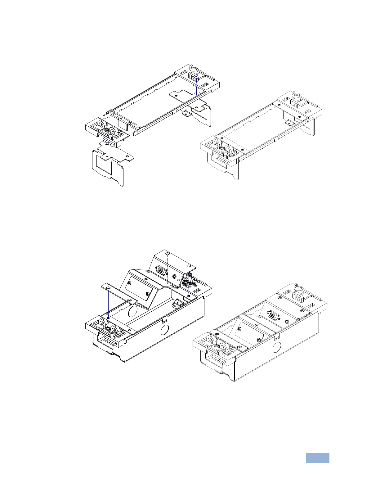
5.3 Installing the F-121UK inside the Ackermann Floor Box
To install the F-121UK inside the Ackermann floor box :
1. Remove the Ackermann box from the Ackermann floor box.
2. Unscrew the three screws holding the box together: one on the lower side of
the box and the third one on top.
3. Separate the two red plastic parts.
4. Unscrew the two screws on each side of the brackets on the F-121UK (four
in total) and put the screws to one side (you will need them later; see step
7).
F-121UK - Installing the F-121UK 9
9
5. Insert the bracket tabs into the opening on each of the red Ackermann
plastic parts and attach both parts.
6. Place the plastic parts with the connected brackets over the Ackermann box
and screw tight in three places (two underneath and one on top).
7. Place the F-121UK main part over the brackets and tighten to the brackets
using the four screws you previously put to one side (in step 4).
8. Push the Ackerman box into the floor box, by applying force if necessary.
You do not need to repeat this procedure when connecting or disconnecting the
lines, just remove the F-121UK by unscrewing the four screws and then replacing
them.

10 F-121UK - Installing the F-121UK
Figure 3 shows the F-121UK fitted in an Ackermann floor box:
Figure 3: F-121UK F itted in an Ackermann Floor Box
5.4 Connecting the Front Panel Ports
To connect the front panel ports:
1. On the F-121UK transmitter section, connect:
The UXGA source (for example, a laptop) to the PC IN 15-pin HD (F)
connector
An audio source to the AUDIO IN 3.5mm mini jack, for example, using a
Kramer C-GMA/GMA cable (VGA 15-pin HD (M) +Audio jack to VGA
15-pin HD (M) +Audio jack). Note that the C-GMA/GMA cable is not
supplied with the unit
2. Connect the appropriate c onnect ors to the inserts.

F-121UK - Installing the F-121UK 11
11
5.5 Wiring the 8-pin Terminal Block Line Output Connector
The 8-pin terminal block is an easy plug-in connector for attaching the STP/UTP
cable. Follow the colors of the color-coded sticker on these terminals for proper
connection of the STP/UTP cable.
Figure 4 defines the pinouts for the terminal
block.
Figure 4: Terminal Block Pinouts
Use the connector clips only when removing wires, not when inserting
them.
Each wire should protrude 9mm (0.35") from the plastic insulation so
that it can be easily connected. To prevent the wires crossing, be sure
that each wire is fully inserted.
Orange / White
GND
12V DC
Green / White
Brown / White
Brown
Green
Blue / White
Blue
Orange
i
12 F-121UK - Installing the F-121UK
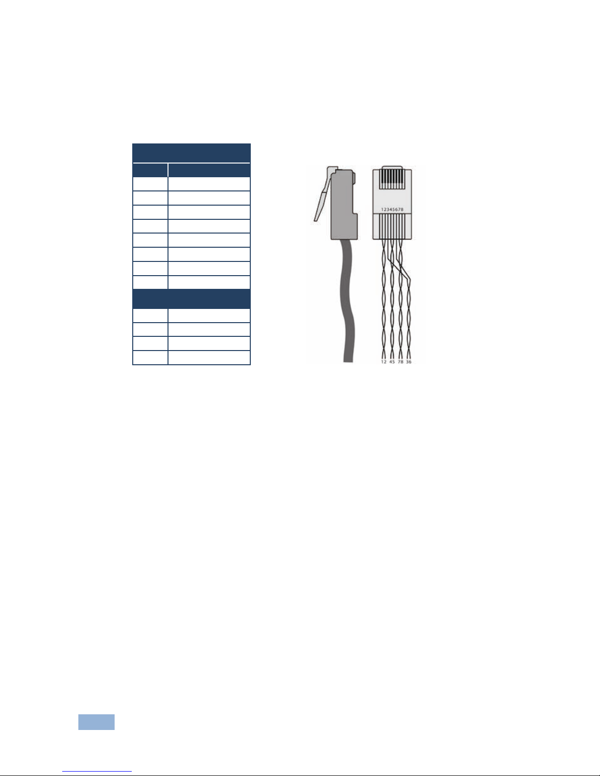
5.6 Wiring the CAT 5 LINE IN / LINE OUT RJ-45 Connectors
This section defines the CAT 5 pinout, using a straight pin-to-pin cable with RJ-45
connectors.
EIA /TIA 568B
Figure 5: CAT 5 PINOUT
PIN Wire Color
1 Orange / White
2 Orange
3 Green / White
4 Blue
5 Blue / White
6 Green
7 Brown / White
8 Brown
Pair 1 4 and 5
Pair 2 1 and 2
Pair 3 3 and 6
Pair 4 7 and 8

F-121UK - Technical Specifications 13
13
6 Technical Specifications
INPUTS: 1 UXGA on a 15-pin HD (F) connector
1 Unbalanced stereo audio on a 3.5mm mini connector
1 Power 12V DC on 2-pin terminal block
OUTPUT: 1 STP/UTP on an 8-pin terminal block with springs
MAX. OUTPUT
LEVEL:
Video: 1.9Vpp Audio: 2.7Vpp
RESOLUTION: Up to UXGA
AUDIO
BANDWIDTH:
20kHz
S/N RATIO: Video: 60dB @5MHz Audio: 78dB @1KHz
CONTROLS: Video detection LED
COUPLING: Video: AC Audio: AC
AUDIO THD +
NOISE:
0.04%
AUDIO 2nd
HARMONIC:
0.001%
POWER
SOURCE:
12V DC 340mA (feeding TP-122-od receiver); self current 110mA
DIMENSIONS: With brackets: 7.5cm x 21.2cm x 4.9cm (2.96” x 8.34" x 1.96") W, D, H
Without brackets: 7.5cm x 15.1cm x 4.9cm (2.96” x 5.93" x 1.96") W, D, H
WEIGHT: 0.19kg (0.42lbs) approx.
ACCESSORIES: Power supply
Specifications are subject to change without notice at Uhttp://www.kramerelectronics.comU

14 F-121UK

For the latest information on our products and a list of Kramer distributors,
visit our Web site where updates to this user manual may be found.
We welcome your questions, comments, and feedback.
Web site:
E-mail:
www.kramerelectronics.com
info@kramerel.com
!
SAFETY WARNING
Disconnect the unit from the power
supply before opening and servicing
 Loading...