

Page 1

USER MANUAL
MODEL:
VG A E xt en der
P/N: 2900-300286 Rev 2
Page 2

VGA Extender – Contents
i
Contents
1 Introduction 1
2 Getting Started 2
2.1 Achieving the Best Performance 2
2.2 Safety Instructions 3
2.3 Recycling Kramer Products 3
3 Overview 4
4 Connecting the VGA Extender System 5
4.1 Connecting the Transmitter 6
4.2 Connecting the Receiver 6
4.3 Connecting the CAT 5/6/7 Cable 7
4.4 Connecting the Power Supply 7
4.5 Connecting the Line Splitter 7
5 Operating the VGA Extender 9
5.1 LED Indicators 9
5.2 Switching On 9
5.3 Adjusting the Picture 9
6 Technical Specifications 10
Figures
Figure 1: VGA Extender System 5
Figure 2: Expanded VGA Extender System Overview 5
Figure 3: Connecting the Transmitter 6
Figure 4 VDS Dual Screen Connections 6
Figure 5 Line Splitter 7
Figure 6 Detailed Connections 8
Page 3

VGA Extender - Introduction
1
1 Introduction
Welcome to Kramer Electronics! Since 1981, Kramer Electronics has been
providing a world of unique, creative, and affordable solutions to the vast range of
problems that confront video, audio, presentation, and broadcasting professionals
on a daily basis. In recent years, we have redesigned and upgraded most of our
line, making the best even better!
Our 1,000-plus different models now appear in 11 groups that are clearly defined
by function: GROUP 1: Distribution Amplifiers; GROUP 2: Switchers and Routers;
GROUP 3: Control Systems; GROUP 4: Format/Standards Converters; GROUP 5:
Range Extenders and Repeaters; GROUP 6: Specialty AV Products; GROUP 7:
Scan Converters and Scalers; GROUP 8: Cables and Connectors; GROUP 9:
Room Connectivity; GROUP 10: Accessories and Rack Adapters and GROUP 11:
Sierra Products.
Congratulations on purchasing your Kramer VGA Extender, which is ideal for the
following typical applications:
Digital signage
Media extension
Page 4

2
VGA Extender - Getting Started
Go to http://www.kramerelectronics.com to check for up-to-date
user manuals, application programs, and to check if firmware
upgrades are available (where appropriate).
This equipment is to be used only inside a building. It may only be
connected to other equipment that is installed inside a building.
i
!
2 Getting Started
We recommend that you:
Unpack the equipment carefully and save the original box and packaging
materials for possible future shipment
Review the contents of this user manual
2.1 Achieving the Best Performance
To achieve the best performance:
Use only good quality connection cables (we recommend Kramer high-
performance, high-resolution cables) to avoid interference, deterioration in
signal quality due to poor matching, and elevated noise levels (often
associated with low quality cables)
Do not secure the cables in tight bundles or roll the slack into tight coils
Avoid interference from neighboring electrical appliances that may adversely
influence signal quality
Position your Kramer VGA Extender away from moisture, excessive sunlight
and dust
Page 5

VGA Extender - Getting Started
3
Caution:
There are no operator serviceable parts inside the unit
Warning:
Use only the Kramer Electronics input power wall
adapter that is provided with the unit
Warning:
Disconnect the power and unplug the unit from the wall
before installing
!
2.2 Safety Instructions
2.3 Recycling Kramer Products
The Waste Electrical and Electronic Equipment (WEEE) Directive 2002/96/EC
aims to reduce the amount of WEEE sent for disposal to landfill or incineration by
requiring it to be collected and recycled. To comply with the WEEE Directive,
Kramer Electronics has made arrangements with the European Advanced
Recycling Network (EARN) and will cover any costs of treatment, recycling and
recovery of waste Kramer Electronics branded equipment on arrival at the EARN
facility. For details of Kramer’s recycling arrangements in your particular country
go to our recycling pages at http://www.kramerelectronics.com/support/recycling/.
Page 6

4
VGA Extender - Overview
Kramer Model
Kramer Part
Number
Full Description
EXT-VGA
(0VS23077)
50-0000999011
Minicom CAT5 VGA Extender
3 Overview
The VGA Extender extends video (VGA) signals up to 110m (360ft) depending on
the resolution.
The VGA Extender is made up of three components:
VDS transmitter
VDS dual screen receiver
Optional CAT 5 VDS line splitter
This table defines the models:
The VGA Extender features:
A maximum range of up to 110m (360ft)
Support for CAT 5/6/7 FTP/UTP cable
Plug and Play installation with no extra protocols needed
Cascadability – adding VDS line splitters increases the number of receivers
up to 64
The VDS transmitter supports the following resolutions:
720 x 400p @70Hz - IBM VGA
640 x 480p @60Hz - IBM VGA
640 x 480p @67Hz - Apple Mac II
640 x 480p @72Hz - VESA
640 x 480p @75Hz - VESA
800 x 600p @56Hz - VESA
800 x 600p @60Hz - VESA
800 x 600p @72Hz - VESA
800 x 600p @75Hz - VESA
832 x 624p @75Hz - Apple Mac II
1024 x 768p @60Hz - VESA
1024 x 768p @70Hz - VESA
1024 x 768p @75Hz - VESA
1280 x1024p @75Hz - VESA
1152 x 870p @75Hz - Apple Mac II
1600 x1200p @60Hz - VESA STD
1280 x1024p @60Hz - VESA STD
1280 x 960p @60Hz - VESA STD
1152 x 864p @75Hz - VESA STD
Page 7
VGA Extender - Connecting the VGA Extender System
5
4 Connecting the VGA Extender System
This section describes how to connect the VGA Extender system.
Before installation:
Switch off the computer
Place cables away from fluorescent lights, air conditioners, and machines
that are likely to generate electrical noise
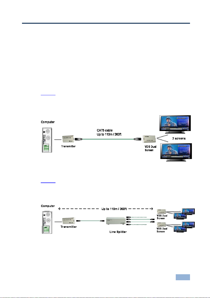
Figure 1 illustrates an overview of the VGA Extender system.
Connect the receiver to one or two screens, up to 110m/360ft away from the
transmitter (depending on resolution).
Figure 1: VGA Extender System
Figure 2 illustrates the VGA Extender system with a connected Line Splitter
adding up to 14 more screens to the system. (With cascading you can have a
maximum of 64 screens).
Figure 2: Expanded VGA Extender System Overview
Page 8

6
VGA Extender - Connecting the VGA Extender System
Keybd
Mouse
100T
Video
Serial A
Parallel
Serial B
Transmitter
To USB Port
To Video
port
To VDS Dual Screen
/ Line Splitter
System cable to
Transmitter / Line
Splitter
To
monitors
VDS Dual Screen
4.1 Connecting the Transmitter
Figure 3 illustrates how to connect the transmitter:
Figure 3: Connecting the Transmitter
Note. Although we recommend connecting the transmitter to a computer that is
switched off, you can connect it to a computer that is switched on.
4.2 Connecting the Receiver
To do so, you must connect it in the following order:
USB connector
Video connector
Figure 4 illustrates how to connect the VDS Dual Screen receiver:
Figure 4 VDS Dual Screen Connections
Page 9
VGA Extender - Connecting the VGA Extender System
7
w
w
w . m i n i c o m . c o m
SYSTEM IN
12VDC
SYSTEM OUT
System cables
Power
connector
CAT5 cable from Transmitter or
previous Line Splitter
4.3 Connecting the CAT 5/6/7 Cable
A CAT 5/6/7 cable connects to the RJ-45 ports of the transmitter and the VDS
Dual Screen.
4.4 Connecting the Power Supply
Connect the supplied 5V DC power adapter to the receiver. The transmitter is
powered only via its USB connection.
Note: If connected to a USB hub, the hub must be powered.
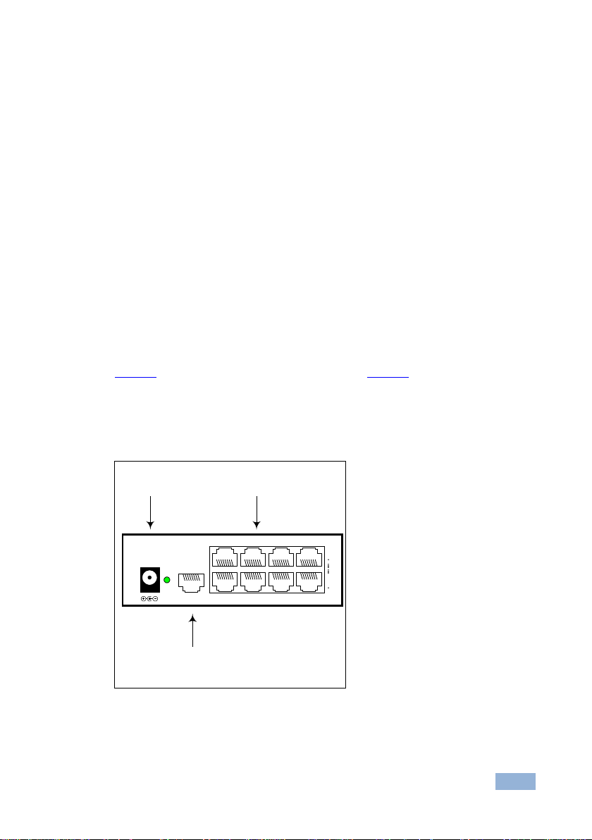
4.5 Connecting the Line Splitter
Connect up to 64 screens by adding up to 2 levels of CAT 5 video display line
splitters to the VGA Extender system.
Figure 5 illustrates the ports of the line splitter and Figure 6 illustrates the detailed
connections of the system including the transmitter, the receivers and a line
splitter.
For the line splitter connect the supplied 12V DC power adapter.
Figure 5 Line Splitter
Page 10

8
VGA Extender - Connecting the VGA Extender System
www.minicom.com
SYSTEM IN
12VDC
SYSTEM OUT
CAT5 cables to
Receivers or Line
Splitter
Line
Splitter
Transmitter
Computer
CAT5 cables to
Receivers or
Line Splitter
To USB Port
To Video port
VDS Dual
Screen
Keybd
Mouse
100T
VideoSerial A
Parallel
Serial B
To wall socket
To wall socket
Figure 6 Detailed Connections
Page 11

VGA Extender - Operating the VGA Extender
9
5 Operating the VGA Extender
5.1 LED Indicators
Both the transmitter and receiver have 2 LEDs above the RJ-45 port.
The green LED indicates power is on. The flashing yellow LED indicates the
system is connected.
5.2 Switching On
Before switching on the computer, connect the transmitter. When fully connected,
the VGA Extender system is ready to transmit video signals.
5.3 Adjusting the Picture
To get a clear projected image, use a screwdriver to turn the picture adjuster on
the VDS Dual Screen receiver unit.
Note: To see a difference you have to turn the picture adjuster several times.
Page 12

10
VGA Extender - Technical Specifications
Transmitter
Receiver
INPUTS:
1 VGA on a 15-pin HD
connector
1 twisted pair on an RJ-45
connector
OUTPUTS:
1 twisted pair on an RJ-45
connector
2 VGA on 15-pin HD
connectors
POWER SUPPLY:
From connected computer
External switching power
adapter 5V DC 110/240
MAX. RESOLUTION:
Up to 1920X1080 @ 60Hz (depending on cable length)
MAXIMUM RANGE:
110m (360ft)
SYSTEM CABLE:
CAT 5/6/7 cable 2x4x24 AWG solid wire
OPERATING TEMPERATURE:
0° to +40°C (32° to 104°F)
STORAGE TEMPERATURE:
-40° to +70°C (-40° to 158°F)
HUMIDITY:
80%, RHL non-condensing
DIMENSIONS:
89mm x 46mm x 25.3mm (3.5” x 1.8” x 0.9”) W. D. H.
WEIGHT:
0.55kg (1.21lb)
Specifications are subject to change without notice at http://www.kramerelectronics.com
6 Technical Specifications
Page 13

Page 14

For the latest information on our products and a list of Kramer distributors,
visit our Web site where updates to this user manual may be found.
We welcome your questions, comments, and feedback.
Web site: www.kramerelectronics.com
E-mail: info@kramerel.com
P/N:
2900-300286
Rev:
2
!
SAFETY WARNIN G
Disconnect the unit from the power
supply before opening and servicing
 Loading...