

Page 1
EXT3-UE-R Quick Start
P/N:
2900- 301654QS
Rev:
2
Scan for full manual
EXT3-UE-R Quick Start Guide
This guide helps you install and use your EXT3-UE -R for the first time.
Go to www.kramerav.com/downloads/EXT3-UE-R to download the latest user manual and check if firmware
upgrades are available.
Step 1: Check what’s in the box
EXT3-UE-R USB Receiver
4 Rubber feet
1 USB-C 2.0 (1.8m) cable
1 Bracket set
1 Quick start guide
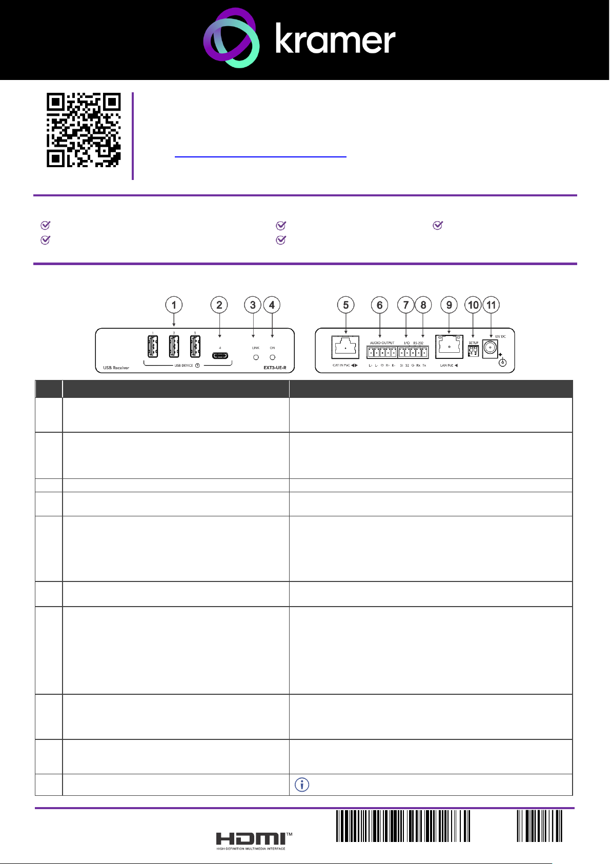
Step 2: Get to know your EXT3-UE-R
#
Feature
Function
1
USB 2 Type A Ports (1 to 3)
Connect to USB local devices (for example, a USB camera, a
soundbar, microphone etc.). Ports provide standard USB device
charging.
2
USB-C Port (4)
Connect to USB local devices (for example, a USB camera, a
soundbar, microphone etc.). Port provides standard USB device
charging.
Note: Port does not provide Power Delivery 2.0 charging.
3
LINK LED
Flashes blue when a link is established.
4
ON LED
Lights green when locally powered by the power adapter. Lights
orange when powered by PoC.
5
CAT IN PoC RJ-45 Connector
Connect to:
• One of the USB CAT OUT PoC ports on the SWT3-41-U-T,
OR,
• CAT A or CAT B on the ACC3-12-SP 1:2 CAT Cable
Splitter which can be connected to the SWT3-41-U-T.
6
AUDIO OUTPUT 5-pin Terminal Block Connector
L+, L-, G)
Connect to a balanced analog stereo audio line acceptor.
7
I/O 2-pin Terminal Block
(S1 to S2)
Connect to:
• Input-triggering devices (for example, remote buttons or
sensors), OR
• Output-triggered devices (for example, remote alarm LED
indication).
These GPIO ports may be configured via paired SWT3-41-U-T
embedded webpages, as digital input or output ports.
8
RS-232 3-pin Terminal Block
(G, Rx, Tx)
Connect to an RS-232 controlled device (for example, the
connected PTZ USB camera) to be controlled via a controller (for
example, SL-240C) which is IP-connected to a paired SWT3-41-
U-T.
9
LAN PoE RJ-45 Connector
Connect to LAN or to an IP-controlled device (for example, the
connected PTZ USB camera). The device accepts power from the
LAN port.
10
SETUP 2-way DIP-switch
All changes in DIP-Switches apply immediately.
Page 2
DIP-switch
Name
DIP-switch
#
DIP-Switch
State
State
Description
RS-232
MODE
1
OFF (up) default
Extension
mode
ON (down)
Programming
mode
For future use
2
Mandatory OFF
(up)
11
12V DC Power Connector
Connect to the power adapter (optional, not included).
The terms HDMI, HDMI High-Definition Multimedia Interface, and the HDMI Logo are trademarks or registered trademarks of HDMI Licensing Administrator, Inc.
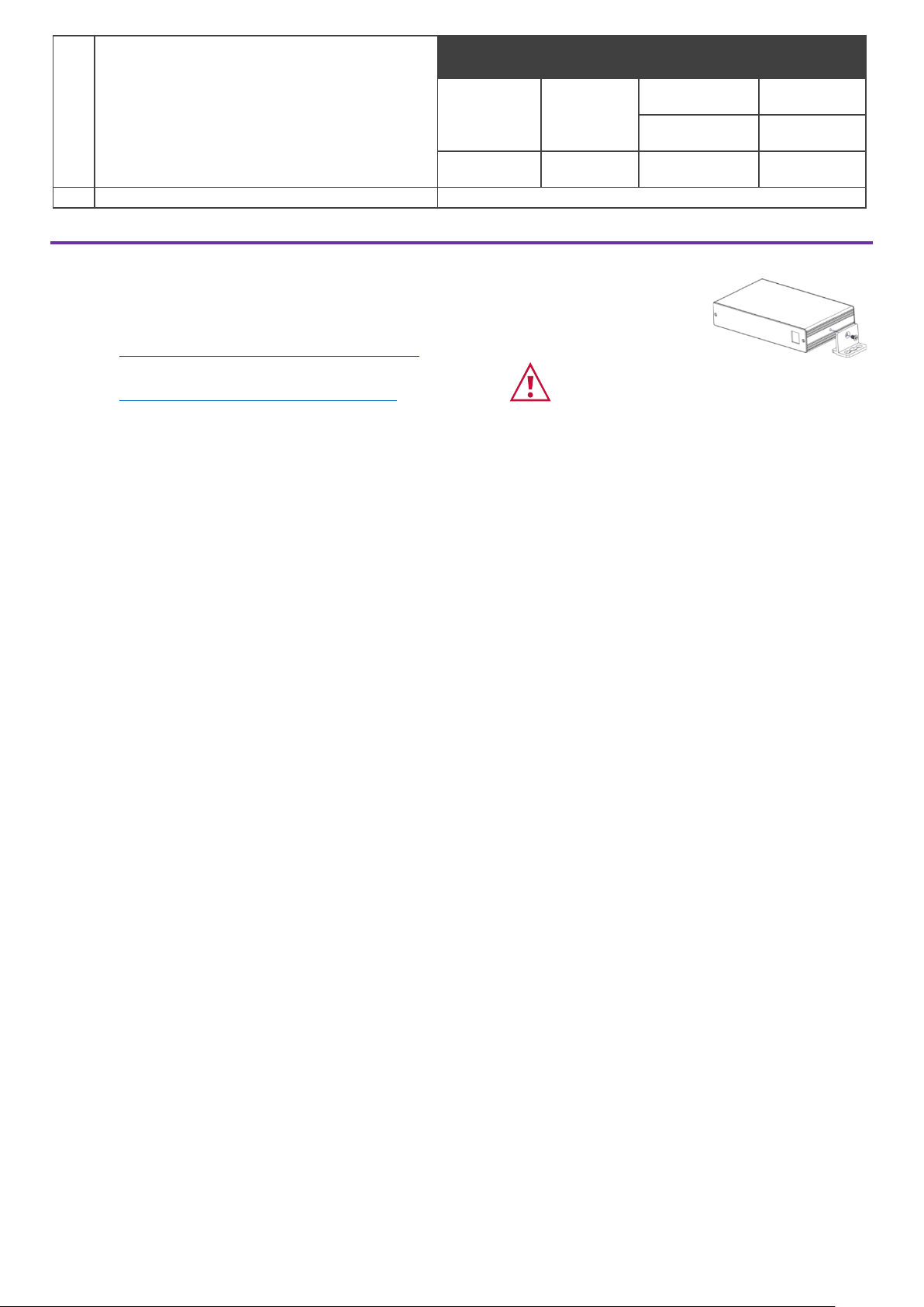
Step 3: Mount EXT3-UE-R
Install EXT3-UE-R using one of the following methods:
• Attach the rubber feet and place the unit on a flat surface.
• Fasten a bracket (included) on each side of the unit and attach it to a flat surface
(see www.kramerav.com/downloads/EXT3-UE-R).
• Mount the unit in a rack using the recommended rack adapter
(see www.kramerav.com/product/EXT3-UE-R).
• Ensure that the environment (e.g., maximum ambient temperature &
air flow) is compatible for the device.
• Avoid uneven mechanical loading.
• Appropriate consideration of equipment nameplate ratings should be
used for avoiding overloading of the circuits.
• Reliable earthing of rack-mounted equipment should be maintained.
• Maximum mounting height for the device is 2 meters.
Page 3

Step 4: Connect inputs and outputs
Always switch OFF the power on each device before connecting it to your EXT3-UE-R.
USB devices that are connected to the EXT3-UE-R USB ports are powered/charged while connected.
Only 9600 baud rate is supported for RS-232 communication for EXT3-UE-R.
Wiring the RJ-45 Connectors
This section defines the TP pinout, using
a straight pin-to-pin cable with RJ-45
connectors.
EIA /TIA 568B
PIN
Wire Color
1
Orange / White
2
Orange
3
Green / White
It is recommended that the cable
ground shielding be
connected/soldered to the connector
shield.
4
Blue
5
Blue / White
6
Green
7
Brown / White
8
Brown
To achieve specified extension distances, use the recommended Kramer cables available at www.kramerav.com/product/EXT3-UE-R.
Using third-party cables may cause damage!
Page 4

Step 5: Connect power
EXT3-UE-R is powered via POC or optional PSU.
Safety Instructions (See www.kramerav.com for updated safety information)
Caution:
• For products with relay terminals and GPI\O ports, please refer to the permitted rating for an external connection, located next to the terminal or in the User Manual.
• There are no operator serviceable parts inside the unit.
Warning:
• Use only the power cord that is supplied with the unit.
• Disconnect the power and unplug the unit from the wall before installing.
 Loading...