

Page 1

P/N: 2900-301670 Rev 8 www.kramerav.com
USER MANUAL
MODELS:
VIA Campus²
Presentation & Collaboration Solution (For
Firmware Version 4.0)
Page 2

Kramer Electronics Ltd.
VIA Campus² – Contents
2
Contents
Contents 2
Introduction 3
Getting Started 3
Overview 5
Glossary 7
Supported Devices 8
Defining VIA Campus² 9
For Installer: Mounting VIA Campus² 10
For Installer: Connecting VIA Campus² 11
Connecting Device 11
Connecting the Main Display 13
For Web Administrator: Gateway Management Pages 16
Logging in to Gateway Management Pages 17
User Management 19
Network Settings 21
VIA Pad Configuration 25
Site Management 27
VIA Screen Editor 28
VIA Settings 41
Display Controller 59
Calendar Integration 60
Recording – Managing Saved Recordings 62
Digital Signage 63
Reports – Activity Logs 72
Utility 73
For Web Administrator: Gateway Dashboard 76
Logging in to the Gateway Dashboard 76
Settings 78
Features - Changing Saved Files Location 85
For User: Connecting via VIA Campus² 86
Installing or Running the VIA app 87
Joining a Room with the VIA app 88
Presenting from the VIA User Dashboard 89
Presenting from a VIA Pad 90
Other Presentation Methods 91
Moderating - Controlling the Meeting 100
Collaborating on the Main Display 102
Using the Whiteboard 103
Chatting and File Sharing 105
For User: Advanced Meeting Functions 106
Using Gateway Dashboard 106
Streaming a Meeting Session 109
Video Conferencing 110
Technical Specifications 113
VIA App Android Permissions 114
Page 3

Kramer Electronics Ltd.
VIA Campus² – Introduction
3
Introduction
Welcome to Kramer Electronics! Since 1981, Kramer Electronics has been providing a world
of unique, creative, and affordable solutions to the vast range of problems that confront the
video, audio, presentation, and broadcasting professional on a daily basis. In recent years, we
have redesigned and upgraded most of our line, making the best even better!
Getting Started
Congratulations on purchasing your VIA Campus² Presentation & Collaboration Solution
(For Firmware Version 4.0).
We recommend that you:
• Unpack the equipment carefully and save the original box and packaging materials for
possible future shipment.
• Review the contents of this user manual.
Go to https://k.kramerav.com/support/product_downloads.asp?pid=4190 to check for up-todate user manuals, application programs, and to check if firmware upgrades are available
(where appropriate).
Achieving Best Performance
• Use only good quality connection cables (we recommend Kramer high-performance,
high-resolution cables) to avoid interference, deterioration in signal quality due to poor
matching, and elevated noise levels (often associated with low quality cables).
• Do not secure the cables in tight bundles or roll the slack into tight coils.
• Avoid interference from neighboring electrical appliances that may adversely influence
signal quality.
• Position your Kramer VIA Campus² away from moisture, excessive sunlight and dust.
This equipment is to be used only inside a building. It may only be connected to other
equipment that is installed inside a building.
Safety Instructions
Caution:
• This equipment is to be used only inside a building. It may only be connected to other
equipment that is installed inside a building.
• For products with relay terminals and GPI\O ports, please refer to the permitted rating
for an external connection, located next to the terminal or in the User Manual.
• There are no operator serviceable parts inside the unit.
Page 4

Kramer Electronics Ltd.
VIA Campus² – Introduction
4
Warning:
• Use only the power cord that is supplied with the unit.
• Disconnect the power and unplug the unit from the wall before installing.
• Do not open the unit. High voltages can cause electrical shock! Servicing by qualified
personnel only.
• To ensure continuous risk protection, replace fuses only according to the rating
specified on the product label which is located on the bottom of the unit.
Recycling Kramer Products
The Waste Electrical and Electronic Equipment (WEEE) Directive 2002/96/EC aims to reduce
the amount of WEEE sent for disposal to landfill or incineration by requiring it to be collected
and recycled. To comply with the WEEE Directive, Kramer Electronics has made
arrangements with the European Advanced Recycling Network (EARN) and will cover any
costs of treatment, recycling and recovery of waste Kramer Electronics branded equipment on
arrival at the EARN facility. For details of Kramer’s recycling arrangements in your particular
country go to our recycling pages at www.kramerav.com/social-responsibility/environment.
Page 5

Kramer Electronics Ltd.
VIA Campus² – Introduction
5
Overview
VIA Campus² is a wireless presentation and collaboration solution that makes it easier to get
actual work done during meetings. With any laptop or mobile device, users can view, edit, and
comment on documents in real time and record sessions. Meeting participants can display or
stream full uninterrupted HD video (up to 1080p60) from their device, and even play
YouTube® videos in full frame rate. In addition to wireless connection, VIA Campus² also
features an HDMI™ wired input.
VIA Campus² can show up to six user screens on a single main display and 12 on two
displays. Users can also view the main display on their own device. VIA Campus² features
iOS mirroring via AirPlay™, Windows & Android mirroring via Miracast™, as well as
ChromeBook mirroring.
VIA Campus² supports 3rd party conferencing and office apps, such as Microsoft Office®,
Skype®, GoToMeeting®, Teams®, and WebEx®. The solution can handle any size
collaboration or meeting space and is ideal for training venues and classrooms.
Key Features
• 3rd party Security Certification.
• Easy and Effective Wireless Connectivity – Built-in Wi-Fi gives you two setup options for
enabling meeting participants to wirelessly join the meeting. After setting a wired
connection from your VIA device to your local corporate LAN you can do one of the
following: use the built-in VIA Wi-Fi to create a guest network to which participants can
connect or use the built-in VIA Wi-Fi as a Miracast receiver.
• Automatically stops presentation when leaving the room.
• 4K@60 HDMI Wired Input – Enables hard-wiring your computer or other HDMI
compatible device such as a camera, multimedia player or computer.
Does not support HDCP signals.
• 60fps Streaming Multimedia – Share up to 4K wireless video streaming (using the VIA
app Multimedia feature).
• One 4K@60 (RGB) HDMI output and one 4K@60 DisplayPort output.
• Remote Power Control — via a relay port.
• iOS, Android, Chromebook® and Miracast® Mirroring.
• Optimized for Video Conferencing – VIA Versa feature enables you to wirelessly select
the professional grade camera and AV in your meeting room for your VC calls.
• Calendar widget on the wallpaper for instant connectivity within one click.
• 3rd Party Web Applications — Run directly from the device without needing to use the
application.
• Seamless Live Video Streaming – Stream live content from meeting rooms, classrooms
and studios using RTMP/RTMPS to all the leading platforms, like YouTube™, Kaltura™,
Panopto™ and more.
Page 6

Kramer Electronics Ltd.
VIA Campus² – Introduction
6
• Room Calendar Integration – Shows the room occupancy schedule on the main display.
• Internal Web Browser – Open any browser to display content.
• DHCP Support.
• Streaming Input for the Internal Media Player.
• Cloud-Based File Sharing – Drag and drop files to the internal VIA cloud storage
(128GB).
• Whiteboard Support.
• Control – Give a participant control over a presenter’s PC for true collaboration.
• Chat – Send an instant message to another user.
• iCloud®, OneDrive®, GoogleDrive®, Dropbox® Integration.
• View Main Display – View the main display on your own device.
• Third-Party App Support – Like Microsoft Office®, Skype for Business®, GoToMeeting®
and WebEx®.
• Icon Shortcuts – On the splash page for third party applications.
• Integrated YouTube Player – Create playlists, share videos or drag and drop any
YouTube clip to your VIA app for seamless video playback.
• Streaming Output – Stream all collaboration activity from the main display to any H.264
decoder.
• Recording – Record an entire VIA video and audio session to a local video file.
• Digital Signage – Display dynamic content and information on the main display when
there is no meeting in progress. Use a predefined template or create your own display
configuration with up to three frames of content that appear simultaneously. Schedule
campaigns (content configurations) to run automatically at specific dates and times.
• Seamless VSM Integration – With VIA Site Management (VSM) software.
• Multilingual Support – Experience VIA in your language.
• Warranty – 3 years on hardware.
Typical Applications
• College and university classrooms.
• Corporate and university training rooms.
Page 7

Kramer Electronics Ltd.
VIA Campus² – Introduction
7
Glossary
The following are definitions of some common terms found in this User Manual.
Screenshots in this section are representative only and may not accurately reflect the
features associated with your VIA device.
• VIA Meeting – A session where one or more users are logged into your VIA unit using
the Kramer VIA app.
• Gateway – A VIA device such as VIA Campus².
• Main Display – The video display that is connected to the HDMI output of the gateway.
This is where presentation and collaboration during the meeting happens.
• User Dashboard (VIA app) – Main interface for meeting participants using the VIA app.
This dashboard appears after logging into a VIA meeting.
Figure 1: User Dashboard
Page 8

Kramer Electronics Ltd.
VIA Campus² – Introduction
8
• Gateway Dashboard (on Main Display) – VIA Campus² interface opened from the main
display using a keyboard and mouse connected to the device (or by using Collaboration
mode). Click the VIA icon in the lower left corner of the main display to open the
Gateway Dashboard.
Figure 2: Gateway Dashboard
• Gateway Management Web Pages (accessed from a PC) – Web pages embedded in
your gateway device that enable you to configure this specific device. The Gateway
Management Web Pages are accessed from any computer connected to the same
network as the gateway.
Supported Devices
The following user devices are supported by the VIA Campus² Presentation &
Collaboration Solution (For Firmware Version 4.0):
• Windows 8/10/11® (32-bit/64-bit) computer.
• Macintosh® computer, using OSX 10.12.x or newer.
• Chromebook.
• iPad/iPhone® tablet/smartphone (iPad 2 or later, iOS 12 or later).
When using the Airplay service, no Kramer VIA application is needed. However, we
recommend using iOS12, Mojave OS X, or higher, for a better experience.
• Android® OS 5. x tablet/smartphone or newer.
The minimum system requirement for using the Kramer VIA mirroring feature for
an Android device is Android 5.1.
Page 9

Kramer Electronics Ltd.
VIA Campus² – Defining VIA Campus²
9
Defining VIA Campus²
This section defines VIA Campus².
Figure 3: VIA Campus²
#
Feature
Function
Power Button
Turns the machine on and off. Logo lights when the unit is turned on.
USB 2.0 Connector
For connecting a USB device.
DC IN 19V Connector
Connects to the 19V DC power adapter.
Wi-Fi Antenna Port (1 of 2)
Connect one of the Wi-Fi antennas for collaborating via the built-in Wi-Fi.
HDMI OUT Connector
Connect to an HDMI display.
DP OUT Connector
Connect to a DisplayPort display.
USB 2.0 Connectors
Connect to up to 2 USB devices.
LAN RJ-45 Connector
Connect a Local Area Network (LAN) cable
USB 3.2 Connectors
Connect to up to 2 USB devices.
AUDIO MIC IN 3.5mm Jack
Connect to a microphone.
Wi-Fi Antenna Port (2 of 2)
Connect one of the Wi-Fi antennas for collaborating via the built-in Wi-Fi.
AUDIO LINE OUT 3.5mm Jack
Connect to an unbalanced stereo audio acceptor.
REMOTE 2-pin Terminal Block
Connect to a toggle switch to remotely turn the device on and off.
1
2
3 4 5
6 7 8
9
10
11
12
13
Page 10

Kramer Electronics Ltd.
VIA Campus² – For Installer: Mounting VIA Campus²
10
For Installer: Mounting VIA Campus²
This section provides instructions for mounting VIA Campus². Before installing, verify that the
environment is within the recommended range:
• Operation temperature – 0 to 40C (32 to 104F).
• Storage temperature – -40 to +70C (-40 to +158F).
• Humidity – 10% to 90%, RHL non-condensing.
Caution:
• Mount VIA Campus² before connecting any cables or power.
Warning:
• Ensure that the environment (e.g., maximum ambient temperature & air flow) is
compatible for the device.
• Avoid uneven mechanical loading.
• Appropriate consideration of equipment nameplate ratings should be used for avoiding
overloading of the circuits.
• Reliable earthing of rack-mounted equipment should be maintained.
To mount VIA Campus² on a rack:
Mount the unit in a rack using the recommended rack adapter
(see www.kramerav.com/product/VIA Campus²)
Page 11

Kramer Electronics Ltd.
VIA Campus² – For Installer: Connecting VIA Campus²
11
For Installer: Connecting VIA Campus²
Always switch off the power to each device before connecting it to your VIA Campus². After
connecting your VIA Campus², connect its power and then switch on the power to each
device.
Connecting Device
Figure 4: Connecting to the rear panel
To connect the VIA Campus² as illustrated in (Figure 4):
1. Connect the keyboard and mouse to the USB Connectors and .
2. Connect one of the following to be used as the main display for the meeting
(see Connecting the Main Display on page 13):
▪ HDMI display to the HDMI OUT Connector .
▪ DisplayPort display to the DisplayPort Connector .
If you are connecting 2 screens, see Configuring dual displays on page 13.
A touchscreen display is best for annotation.
3. Connect a Local Area Network (LAN) cable to the LAN RJ-45 Connector for
connection to your network.
VIA Campus² can be connected to a local area network (LAN). In this setup, the default
IP setting is DHCP that assigns an automatic IP address to your unit. This enables easy
Plug and Play setup when connecting your VIA Campus² to the network. To assign a
static IP address, (see Settings on page 78).
7 9 5 6 8
Page 12
Kramer Electronics Ltd.
VIA Campus² – For Installer: Connecting VIA Campus²
12
4. Connect the Wi-Fi antennas to the Wi-Fi Antenna Ports and for using the built-in
wireless capability.
5. Connect powered speakers and a microphone to the AUDIO Mini Jacks and .
6. Connect the 19V DC power adapter to the Power Connector and plug it into the
mains electricity.
Do not turn the device on before connecting the LAN port to the network.
7. Connect via Wi-Fi with any of the following types of devices:
To enable participation in a collaborative session (send and receive content), all
participant devices (PCs/ MACs/ smartphones/tablets) must be connected to the
same network (LAN - wired/wireless) as the VIA Campus².
▪ A Windows 7 and above (32-bit/64-bit) computer.
▪ A Macintosh® computer, using OSX 10.11.x or newer.
▪ An iPad/iPhone® tablet/smartphone with the VIA app installed (iPad 2 or later, iOS 10
or later).
When using the Airplay service, no application is needed. However, we recommend
using iOS 12, Mojave OSX, or higher, for a better experience.
▪ An Android® OS 5.x tablet/smartphone with the VIA app installed.
For using the Android mirroring feature, a device equipped with Android 5. 1 minimum
is required.
8. Connect a USB device to the USB 2.0 Connector on the front panel.
VIA Campus² is connected.
4
11
10
12
3
2
Page 13

Kramer Electronics Ltd.
VIA Campus² – For Installer: Connecting VIA Campus²
13
Connecting the Main Display
The main display is the screen connected directly to the VIA Campus². When VIA Campus²
is booted up, the VIA gateway screen appears on the main display. All collaboration activity is
then displayed here.
Connect one or both of the following types of displays:
• HDMI – The HDMI OUT Connector connects to any compatible projection or direct-
view display, such as an LCD monitor. This connection can be routed and switched.
• DisplayPort – The DisplayPort Connector connects to a DisplayPort display or to a
VGA display by means of a DP to VGA adapter cable.
TTt
The VIA Campus² internal video card reads the EDID (Extended Display Identification Data)
of the connected displays and sets the optimum display resolution and image refresh rate
automatically.
Configuring dual displays
If two displays are connected to the VIA Campus², you have several display options:
• Show different content on each screen: One display shows the conferencing (the
source is a shared screen or app) and the other displays any media source that is being
streamed.
• The displays act as a single extended display (the mouse can roam across both
screens).
• Both displays show the same content (they “mirror” each other).
To configure the displays:
1. Open the Gateway Dashboard on the Main Display:
a. Connect a keyboard and mouse to the USB
input of the VIA Campus².
b. Click the VIA icon in the lower left of
the main display. If there is no VIA icon press
CTRL-Tab and select the Collaboration
menu. The Gateway Dashboard opens.
5
6
Page 14

Kramer Electronics Ltd.
VIA Campus² – For Installer: Connecting VIA Campus²
14
2. Click System Controls. The login window appears.
a. Enter the administrator username and password (default username = su, default
password = supass).
3. On the System Controls tab, click Display. The Display menu opens:
a. Page down to Multiple
displays and set how you
want the displays handled:
Extend, Duplicate or Use just
one of the displays.
Note: If you want to display
different content on each
screen, set Multiple displays
to Extend these displays.
b. If you set it to Extend the
displays: The primary display
is 1 and the secondary display
2.
4. Exit the Gateway Dashboard.
5. If you want to show different content on each screen, in the Gateway Management
pages:
a. Connect your computer to the same network as the VIA Campus².
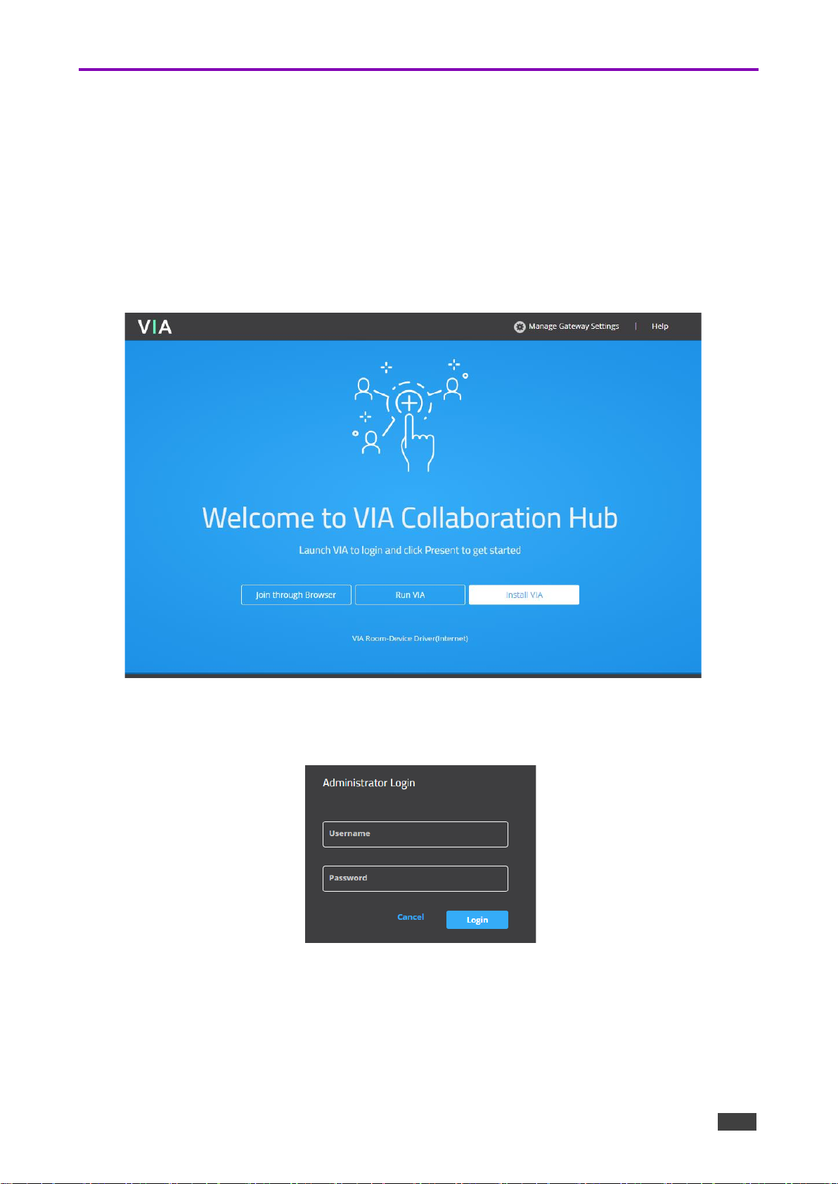
b. In a Web browser, open the IP address of your VIA Campus². The VIA Collaboration
Hub page appears.
Figure 5: VIA Collaboration Hub
Page 15

Kramer Electronics Ltd.
VIA Campus² – For Installer: Connecting VIA Campus²
15
c. Click Manage Gateway Settings in the upper right corner; The Administrator Login
page appears (default username = su, default password = supass).
Figure 6: Administrator Login
d. In the menu on the left, select Device Management > VIA Settings.
Figure 7: VIA Setting Page
e. In the VIA Settings page, click the Edit icon of the Active layout.
f. Click Presentation in the All VIA settings list.
g. Page down to Screen Reservation (For Dual Display Setups).
Figure 8: Presentation tab of the All VIA settings
h. Enable Conferencing Mode (you cannot enable both modes at the same time).
i. Select the screen that will display Conferencing (the Primary Screen or the
Secondary Screen).
j. Enable Media Mode and make sure it is set to display on the other screen.
k. Click Update Template (top right of the window) and then Publish & Exit.
Dual displays have been configured.
Page 16

Kramer Electronics Ltd.
VIA Campus² – For Web Administrator: Gateway Management Pages
16
For Web Administrator: Gateway Management Pages
VIA Campus² administration is divided into two groups of settings:
• Gateway Management Pages – Control general device settings (see the list below).
These are the high-level controls that can only be accessed over LAN, with an
administrator’s password.
• Gateway Dashboard - Controls the User Dashboard interface presented to meeting
participants. Only accessible with a mouse and keyboard connected to the VIA
Campus². Limitations can be set by the Management Pages that prevent/allow non-
administrators to change some of the settings (see For Web Administrator: Gateway
Dashboard on page 72).
Figure 9: VIA Campus² hierarchy of control
Page 17
Kramer Electronics Ltd.
VIA Campus² – For Web Administrator: Gateway Management Pages
17
Logging in to Gateway Management Pages
The Gateway Management Pages enable you to configure your VIA Campus² gateway
device. The Gateway Management Pages are accessed from any computer connected to the
same network as your gateway.
To Log in to the VIA Campus² Gateway Management Pages:
1. Connect your computer to the same network as the VIA Campus².
2. Open a Web browser and go to the IP address for your VIA Campus² unit.
The VIA Collaboration Hub page appears.
Figure 10: VIA Collaboration Hub
3. Click Manage Gateway Settings in the upper right corner.
The Administrator Login page appears.
Figure 11: Administrator Login
4. Type a Web Administrator Username (default = su) and Password (default = supass).
5. Click Login; The Gateway Management Pages appear with the Dashboard overview
open.
Page 18

Kramer Electronics Ltd.
VIA Campus² – For Web Administrator: Gateway Management Pages
18
Figure 12: Gateway Management Dashboard
6. The Gateway Management Dashboard provides a grand overview of the system:
▪ System Status (the top data row) – Shows hardware and software status (can be
used to update the firmware).
▪ Services – Shows the live connection status.
▪ LAN – Shows an overview of the network settings.
▪ WIFI – Shows an overview of the WiFi settings.
▪ Audio – Shows the audio output device (click Change audio setting to update).
▪ Site Management – If VSM (VIA Server Management) is active and controlling device
settings, its details will be displayed in this section.
Click the tabs in the navigation pane on the left to display the VIA web pages.
Click the arrow in the upper right corner to select a different language for the web
pages.
Page 19
Kramer Electronics Ltd.
VIA Campus² – For Web Administrator: Gateway Management Pages
19
User Management
This section describes how to add user accounts to the database of your VIA Campus²
device. User accounts are required to access the Gateway Management Pages and,
depending on settings (see Moderator Mode on page 50), a user account can be required for
people to join a VIA meeting.
To add a user account to your VIA Campus² database:
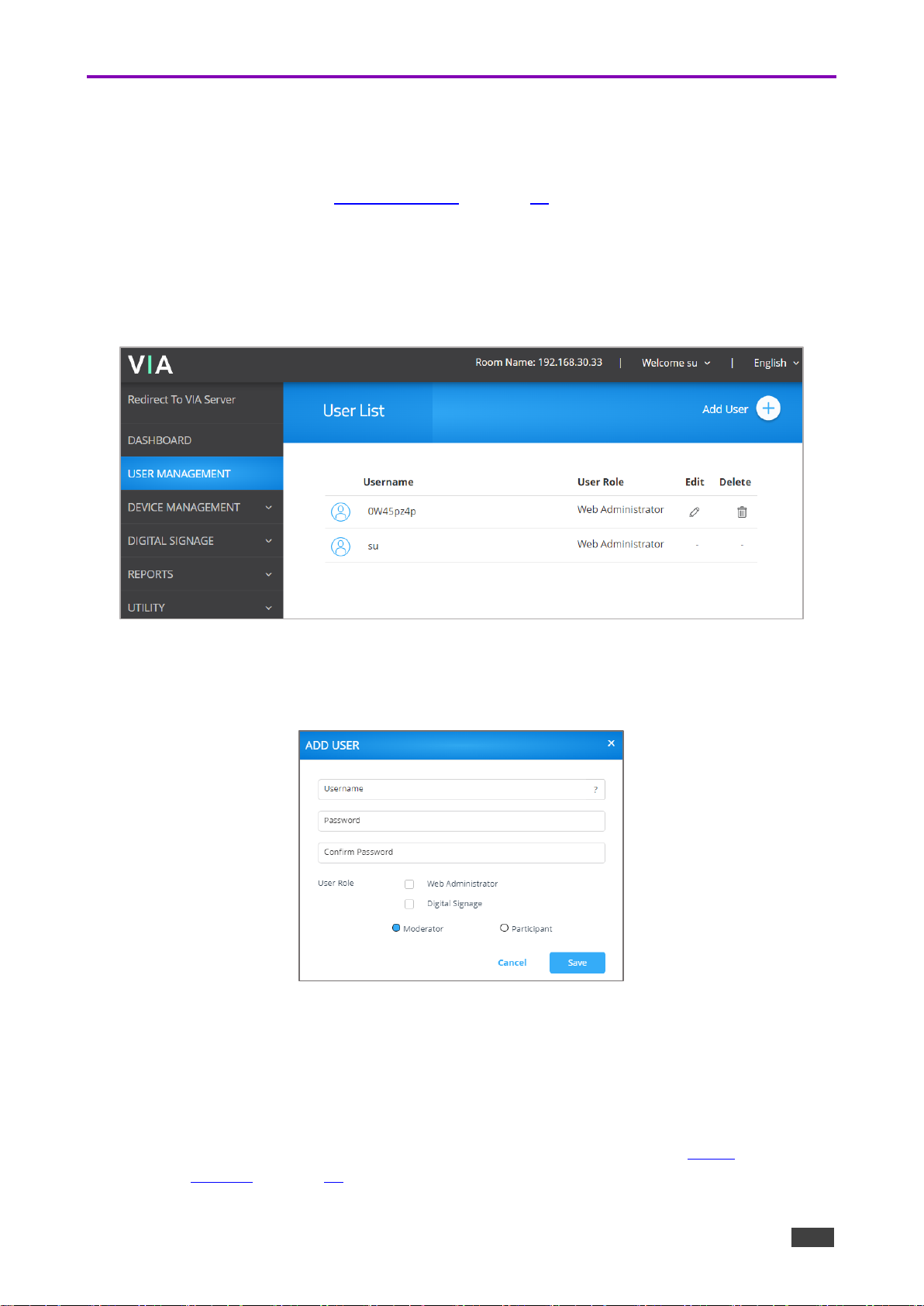
1. Click User Management on the Gateway Management Pages navigation pane.
The User List page appears.
Figure 13: User Management Page
2. Click Add User.
The Add User pane appears.
Figure 14: Add User Pane
3. Type the new Username, Password and Confirm Password.
4. Under User Role, select from the following administrative levels:
▪ Web Administrator – Access to change all system settings, including Digital
Signage.
▪ Digital Signage – Able to configure the Digital Signage only (see Digital
Signage on page 63).
Page 20

Kramer Electronics Ltd.
VIA Campus² – For Web Administrator: Gateway Management Pages
20
5. Select one of the following participation levels:
These options are enabled only when Moderator Mode is enabled (see Moderator Mode
on page 50).
▪ Moderator – User can moderate and has access to moderator features.
▪ Participant – User can join a meeting as a participant but cannot moderate.
6. Click Save.
A new user is added, and the User List tab appears with the new user added to the list.
Page 21

Kramer Electronics Ltd.
VIA Campus² – For Web Administrator: Gateway Management Pages
21
Network Settings
Changing Device IP Address
By default, the IP address of your VIA Campus² is set automatically by DHCP. See below if
you want to set a static IP address.
When changing these settings, please contact your IT administrator. Incorrect values can
cause a loss of communication.
To change the IP address of your VIA Campus² unit:
1. Click Device Management > Network Settings.
The LAN setting tab opens with network setting page.
Figure 15: LAN Settings Page
2. Under Connection Type, select Static.
3. Under Network Information, rename the gateway IP. (Figure 27)
4. Click Apply; The IP address of your VIA Campus² is changed.
Page 22

Kramer Electronics Ltd.
VIA Campus² – For Web Administrator: Gateway Management Pages
22
Setting Up Secure Wireless Guest Access Point
Using the built-in Wi-Fi module, VIA Campus² enables you to set up a secure access point for
users to connect to your VIA Campus² network. This setup is ideal for guest users whom you
may not want to connect directly to your network.
To set up a secure wireless guest access point:
1. Click Device Management > Network Settings; The Network Settings page appears.
2. Click WiFi.
The WiFi tab appears.
Figure 16: AP Mode Tab
3. Enable WiFi. The switch turns green and the WiFi settings appear.
4. Click AP Mode and enter a new name in the SSID field and a new password.
5. Click Apply.
The secure wireless guest access point is set up.
Page 23
Kramer Electronics Ltd.
VIA Campus² – For Web Administrator: Gateway Management Pages
23
Connecting VIA Campus² to a WiFi Network
Connect VIA Campus² as a WiFi client of your main network.
To set up Client WiFi mode:
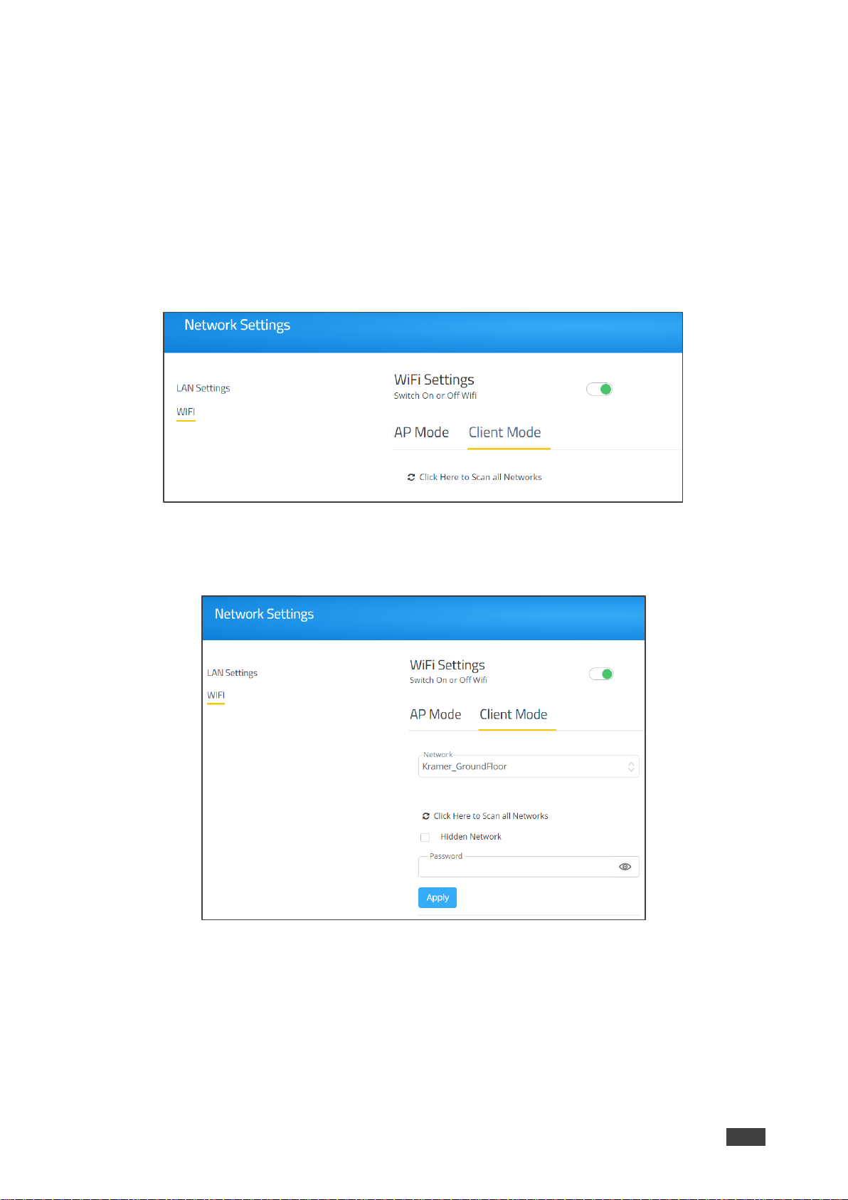
1. Click Device Management > Network Settings; The Network Settings page appears.
2. Click WiFi; The WiFi tab appears.
3. Turn on the WiFi; The switch turns green and the WiFi settings appear.
2. Click Client Mode; The Client Mode tab appears.
Figure 17: Client Mode Tab
3. Select a network from the dropdown (if a network is missing, try Click Here to Scan all
Networks).
Figure 18: Client Mode Settings
4. Select an available network from the drop-down.
5. Enter the network password and click Apply.
6. Disconnect the LAN cable (if connected) and reboot the device.
Client WiFi Mode is set up.
Page 24
Kramer Electronics Ltd.
VIA Campus² – For Web Administrator: Gateway Management Pages
24
Connecting VIA Campus² to 802.1x Network
VIA Campus² enables you to wirelessly connect your VIA Campus² device as a client device
to an 802.1X network using password authentication or EAP-TLS authentication.
EAP-TLS features include:
▪ Mutual authentication (server to the client and client to server).
▪ Key exchange to establish dynamic WEP or TKIP keys.
▪ Fragmentation and reassembly of very long EAP messages, if needed.
▪ Fast reconnect via TLS session resumption.
To Connect VIA Campus² as a client device to an 802.1x network:
1. Set up a Radius server to validate the certificate that you will upload to VIA Campus².
2. Set up an access point (AP) with 802.1x type security.
The Radius server IP address and password will be passed while configuring the 802.1x
security type on the access point. This password is the same one that is used in the
Radius server.
3. Click Device Management > Network Settings in the navigation pane.
The Network Settings page appears.
4. Click WiFi; The WiFi tab appears.
5. Switch on WiFi; When active, the switch turns green and the WiFi settings appear.
4. Click Client Mode; The Client Mode tab appears.
If the desired network is not in the dropdown, click Click Here to Scan all Networks.
5. Do one of the following:
▪ To connect to the network with username and password authentication, select the
SSID of the access point that is secured by 802.1x.
Your unit can now connect to the network with a username and password.
-OR-
▪ To connect to the network with EAP-TLS authentication:
l. Select the 802.1x (TLS Certificate) checkbox; Additional settings appear.
m. Enter the Identity.
n. Upload the Authority CA, User Certificate and Key files and click Apply.
VIA Campus² automatically reboots and is now connected to the 802.1x network.
Page 25

Kramer Electronics Ltd.
VIA Campus² – For Web Administrator: Gateway Management Pages
25
VIA Pad Configuration
VIA Pad is an optional touch-pad accessory that enables meeting participants to instantly join
a VIA meeting with their Mac or PC laptop. Before connecting VIA Pad to a participant device
for the first time, VIA Pad must be paired with your VIA Campus² device. The pairing
procedure includes:
• Configuring VIA Pad Settings on page 25.
• Pairing a VIA Pad Device on page 26.
Configuring VIA Pad Settings
VIA Campus² enables you to configure VIA Pad settings that define how a VIA Pad device
operates when paired with your VIA Campus² unit.
To configure VIA Pad settings:
1. Click Device Management > VIAPad Configuration on the navigation pane.
The VIAPad Configuration page appears.
2. Select the following as required:
Figure 19: VIA Pad Configuration Page
▪ Guest – Participant can Present by touching the VIA Pad device; the Kramer VIA
app dashboard is not available.
▪ VIA Pad overrides Room Code – Participant can join a meeting without entering the
room code.
Room Name is automatically populated; it reflects the IP address of your VIA Campus² unit.
Page 26

Kramer Electronics Ltd.
VIA Campus² – For Web Administrator: Gateway Management Pages
26
3. Select the Auto Connect to Wi-Fi checkbox, to configure VIA Pad to automatically
connect to the meeting space Wi-Fi network; The Auto Connect settings appear.
Figure 20: Auto Connect Settings
4. Define the following for the meeting space Wi-Fi network:
a. SSID – Name of the network
Make sure that you write it EXACTLY as defined. This parameter is case sensitive.
b. Authentication Mode – Security used by your Wi-Fi access point. Select from the pre-
set options: WEP Open, WEP Shared, WPA Personal, WPA2 Personal.
c. Encryption – Type of encryption key used by your router.
d. Key – Password required to join your network (up to 50 characters max).
VIA Pad settings are configured.
After clicking Apply Settings, the configuration is saved, reboot is not required.
Pairing a VIA Pad Device
Each VIA Pad device must be paired to your VIA Campus² unit before it can be used. To pair
a VIA Pad device to your unit, follow the directions below:
Page 27

Kramer Electronics Ltd.
VIA Campus² – For Web Administrator: Gateway Management Pages
27
Site Management
VSM (VIA Site Management) is an optional, web-based software application (purchased
separately) that enables an administrator to monitor and make changes to all VIA gateways
connected to a network. VIA Campus² enables you to activate VSM management for a VIA
gateway and define which gateway functions are managed by VSM.
Contact your regional sales representative for more details about this solution.
If VIA discovery is enabled and configured in VSM, your VIA device is automatically
added under VSM supervision.
To configure VIA Campus² to be managed by VSM when VIA discovery is not activated:
1. Click Device Management > Site Management on the navigation pane.
The VIA Site Management page appears.
Figure 21: Site Management Settings
2. In the Step 1: Server Settings section, enter the VSM Server IP and the Gateway ID that
was defined in VSM for this gateway.
3. Click Validate and Save; Changes take effect immediately.
VIA Campus² must be able to connect to VSM while validating is in progress.
-OR-
Click Save for changes to be saved with no validation from VSM.
Since validation is not made immediately, any error entered at this stage, like
duplication of ID, must be corrected manually at a later stage.
4. In the Step 2: Configuration section, in the VSM column, select all functions that you
want to be managed by VSM.
After clicking Apply and Reset, changes take 30 minutes to 1 hour to take effect, to
allow time to communicate with VSM.
Page 28
Kramer Electronics Ltd.
VIA Campus² – For Web Administrator: Gateway Management Pages
28
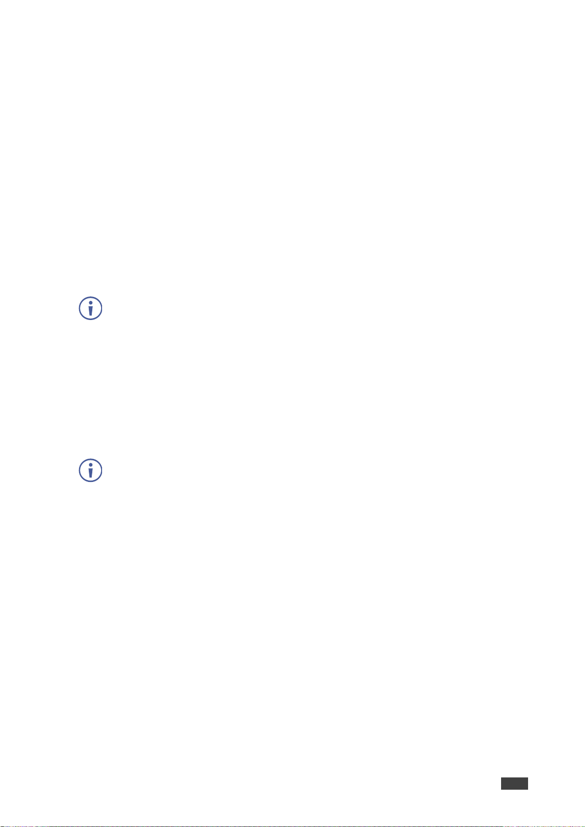
VIA Screen Editor
Customize the look and feel of the main display home screen:
• Creating a New Screen Layout on page 28.
• Formatting Screen Layout Widgets on page 30.
• Editing a Screen Layout on page 38.
• Deleting a Screen Layout on page 38.
• Exporting and Importing a Screen Layout on page 39.
• Scaling Gateway Dashboard for Large Screens on page 40.
Creating a New Screen Layout
Screen layouts are stored as templates which can be copied or exported.
Custom design the screen layout for the main display. You can incorporate your company
branding, as well as display custom text, date & time, and meeting login information. Create
and save several versions of the screen layout and load them as needed.
To create a new screen layout for the main display:
1. Click Device Management > VIA Screen Editor on the Gateway Management Pages
navigation pane.
The Screen Editor page appears.
Figure 22: VIA Screen Editor
Page 29

Kramer Electronics Ltd.
VIA Campus² – For Web Administrator: Gateway Management Pages
29
2. Click Add Screen Layout.
The wallpaper upload window appears.
Figure 23: Wallpaper Upload Window
3. Drag an image file to the window or click Upload a photo from your computer and
select an image file from your computer.
Wallpaper image files must be jpeg, png, or bmp format and a maximum size of 2 MB.
If the wallpaper image resolution does not match VIA's output resolution, the screen layout
elements may not appear in the same location as they do in the Screen Editor. For best
results, use a wallpaper image that matches the output resolution of VIA.
The Screen Editor window appears with the selected image in the work area.
4. Drag one of the following widgets (screen elements) from the left side of the window into
the workspace in the middle:
The widget appears on the screen layout preview and the property controls appear on
the right of the preview.
5. Format the widget with the property controls on the right side of the window
(see Formatting Screen Layout Widgets on page 30).
6. Click and drag the widgets according to your preferred screen layout.
Select the Gridlines checkbox to show a grid overlay that helps position elements on the
layout.
7. Click Save; The new layout is saved and will appear in the table of layouts on the
Screen Editor page.
8. Click Publish.
The new screen layout appears on the main display.
Page 30

Kramer Electronics Ltd.
VIA Campus² – For Web Administrator: Gateway Management Pages
30
Formatting Screen Layout Widgets
• VIA Campus² provides different formatting options for each
layout widget (screen element), such as: The room code
position, format and refresh time or a customized DNS (Domain
Name System) name instead of the default room name.
• Formatting Text on page 31.
• Formatting Room Name 1 on page 32.
• Formatting Room Name 2 on page 33.
• Formatting Room Code on page 33.
• Formatting Code Popup on page 34.
• Formatting Date on page 34.
• Formatting Time on page 35.
• Formatting Date & Time on page 35.
• Formatting QR Code on page 36.
• Formatting Calendar on page 36.
• Formatting Timer on page 37.
Figure 24: Screen Editor Widgets
Page 31

Kramer Electronics Ltd.
VIA Campus² – For Web Administrator: Gateway Management Pages
31
Formatting Text
Format the following on the PROPERTIES tab:
• Enter the text in the text field.
• Select the font size and text alignment.
• Under Auto Resize, click ON to automatically
resize the box to fit the size of the text. When
the layout is published, on the main display the
box size adjusts to fit the size of the text.
Figure 25: Text Properties Tab
Format the following on the COLORS tab:
• Click the Background color box and select a fill color
for the text box.
• Select the Opacity of the text box.
• Click the Font Color box and select a font color.
• Under Border, click ON, click the Border Color box
and select a border color.
Figure 26: Text Color Tab
Page 32

Kramer Electronics Ltd.
VIA Campus² – For Web Administrator: Gateway Management Pages
32
Formatting Room Name 1
Room Name 1 is the address used join a meeting.
Format the following on the PROPERTIES tab:
• In the Room Name field, you can enter one or both of the
following:
▪ #roomname# – Automatically displays the IP address
of the meeting space (default).
• #airplayname# – Automatically displays the airplay name
of the meeting space, see Presenting with iOS/OS X Airplay
Service on page 91).
• In the Custom Room Name field, enter a custom name for
the meeting space. This name appears in place of the
meeting space IP address when #roomname# is used in
the Room Name field (see bullet above).
Custom Room Names do not change the IP address, they add a
custom name that makes it easier to identify the meeting space.
Participants can join with either the room name or the IP address.
Custom room names only work if DNS has been configured to
redirect the Room Name to the IP address or if broadcast is working
in your network environment. We recommend adding a text field and
including the VIA’s IP address on the wallpaper as well as the
custom name.
Figure 27: [Figure Caption]
• Under Show Room Name on second Display also, click ON to show the room name on both
displays, when using dual displays (see Connecting the Main Display on page 13).
• Under Room Name Overlay:
▪ Click ON to always show the room name on top of all content being presented on
the screen.
▪ Select the number of seconds the room name overlay is visible on top of participant
content.
• Select the font size and text alignment.
• Under Auto Resize, click ON to automatically resize the box to fit the size of the text. When
the layout is published, on the main display the box size adjusts to fit the size of the text.
For formatting on the COLORS tab, see Formatting Text on page 31.
Page 33

Kramer Electronics Ltd.
VIA Campus² – For Web Administrator: Gateway Management Pages
33
Formatting Room Name 2
Room Name 2 shows the IP address for a second network, when in use. You cannot create a
custom name for this room name. For an explanation of formatting this widget, see Formatting
Room Name 1 on page 32.
Formatting Room Code
Room Code is the four-digit code that participants need to join the meeting.
Format the following on the PROPERTIES tab:
• Under Always Show on Wallpaper, click ON to
always show the room code on the main display
background. The code will be hidden if there is
content covering it.
• Under Show Room Code on second Display also,
click ON to show the room code on both displays,
(when using dual displays see Connecting the Main
Display on page 13).
• Under Room Code Refresh Time, select the time, in
minutes, to define how long a room code remains
valid before changing to a different code.
• Select the font size and text alignment.
• Under Auto Resize, click ON to automatically resize
the box to fit the size of the text. When the layout is
published, on the main display the box size adjusts
to fit the size of the text.
• Under Always show on wallpaper, click ON to
always show the room code on the main display
background. The code will be hidden if there is
content covering it.
Figure 28: [Figure Caption]
• Under Show Room Code on second Display also, click ON to show the room code on both
displays, when using dual displays (see Connecting the Main Display on page 13).
• Under Room Code Refresh Time, select the time, in minutes, for how long a room code
remains before changing to a different code.
• Select the font size and text alignment.
• Under Auto Resize, click ON to automatically resize the box to fit the size of the text. When
the layout is published, on the main display the box size adjusts to fit the size of the text.
For formatting on the COLORS tab, see Formatting Text on page 31.
Page 34

Kramer Electronics Ltd.
VIA Campus² – For Web Administrator: Gateway Management Pages
34
Formatting Code Popup
Code Popup shows the Room Code only when a
participant enters the Room Name on Kramer VIA
app to join the meeting. This popup appears on top
of any content being presented on the main display.
Format the following on the PROPERTIES tab:
• Select the font size and text alignment.
For formatting on the COLORS tab, see Formatting
Text on page 31.
Figure 29: Room Code Popup Properties Tab
Formatting Date
The Date widget displays the date according to the time zone settings of the VIA device
(see Date/Time on page 48).
Format the following on the PROPERTIES tab:
• Select one of the following date formats:
▪ DD MON, YYYY – Day Month, Year (for
example: 1 January, 2019).
▪ MON DD, YYYY – Month Day, Year (for
example: January 1, 2019).
▪ DD MON – Day Month (for example: 1
January).
▪ MON DD – Month Day (for example: January
1).
• Select the font size and text alignment.
• Under Auto Resize, click ON to automatically
resize the box to fit the size of the text. When the
layout is published, on the main display the box
size adjusts to fit the size of the text.
Figure 30: Date Properties Tab
For formatting on the COLORS tab, see Formatting Text on page 31.
Page 35

Kramer Electronics Ltd.
VIA Campus² – For Web Administrator: Gateway Management Pages
35
Formatting Time
The Time widget displays the time according to the time zone settings of the VIA device
(see Date/Time on page 48).
Format the following on the PROPERTIES tab:
• Select 24 Hour or AM/PM time format.
• Select the font size and text alignment.
• Under Auto Resize, click ON to automatically
resize the box to fit the size of the text. When the
layout is published, on the main display the box
size adjusts to fit the size of the text.
For formatting on the COLORS tab, see Formatting
Text on page 31.
Figure 31: Time Properties Tab
Formatting Date & Time
The Date & Time widget displays the date and time according to the time zone settings of the
VIA device (see Date/Time on page 48).
Format the following on the PROPERTIES tab:
• Select 24 Hour or AM/PM time format.
• Select the font size and text alignment.
• Under Auto Resize, click ON to automatically resize
the box to fit the size of the text. When the layout is
published, on the main display the box size adjusts
to fit the size of the text.
For formatting on the COLORS tab, see Formatting Text
on page 31.
Figure 32: Date & Time Properties Tab
Page 36

Kramer Electronics Ltd.
VIA Campus² – For Web Administrator: Gateway Management Pages
36
Formatting QR Code
The QR Code widget is a QR code that enables a participant to join the meeting by scanning
the code with their device.
Format the following on the PROPERTIES tab:
• Under Enable QR code, click ON to enable
joining the meeting using the QR code.
• Under Bypass room code, click ON to enable
joining the meeting using the QR code without
entering the room code.
• Under Keep QR code always on top, click ON
to always show the QR code on top of all
content being presented on the screen.
Figure 33: QR Code Properties Tab
To download and print a hard copy of the
QR code to post in the meeting space, go
to the Screen Editor page and click the QR
code icon in the Preview column of the
active screen layout.
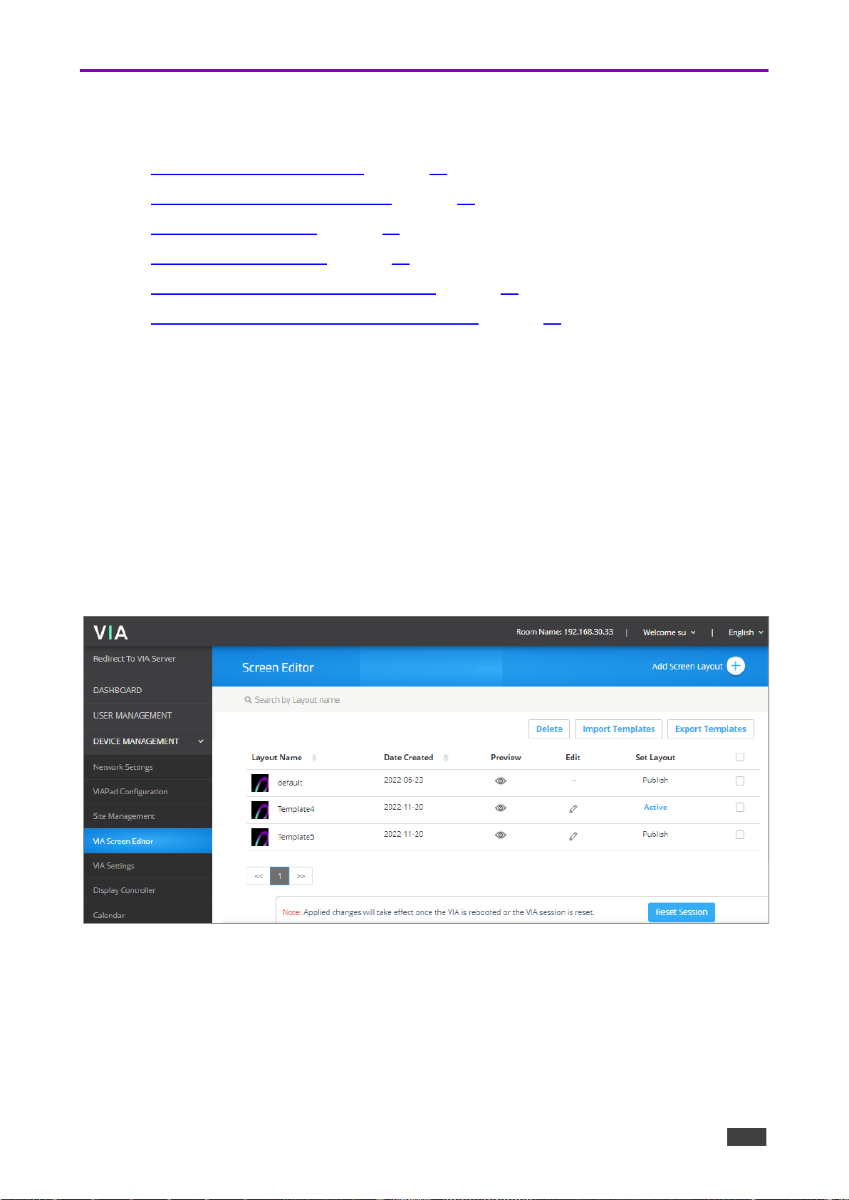
Formatting Calendar
The Calendar widget displays information about meetings scheduled in the room where the
VIA device resides.
The VIA Calendar feature must be configured and activated to use this widget (see Calendar
Integration on page 60)
Format the following on the PROPERTIES tab:
• Select 24 Hour or AM/PM time format.
• Under Show Title, click ON/OFF to
show/hide the meeting title.
• Under Show Organizer, click ON/OFF to
show/hide the name of the meeting
organizer.
• Under No. of Records to Display, select how
many upcoming meetings to display.
• Under Please choose font size, select the
font size.
Figure 34: Calendar Properties Tab
Page 37
Kramer Electronics Ltd.
VIA Campus² – For Web Administrator: Gateway Management Pages
37
Format the following on the COLORS tab:
• Click the Background Color box and select a
fill color for the calendar.
• Select the opacity of the calendar.
• Click the Meeting Tile Font Color box and
select a font color.
• Select a bar color for the following meeting
statuses:
▪ In Use.
▪ Available.
▪ Upcoming.
Figure 35: Calendar Colors Tab
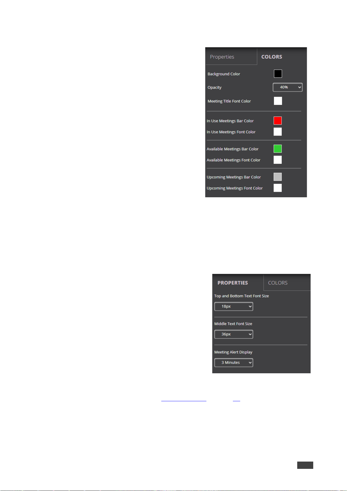
Formatting Timer
The Timer widget is a pop-up that displays a notification that counts down the last several
minutes before the next meeting is scheduled to start in the room.
Format the following on the PROPERTIES tab:
• Under Top and Bottom Text Font Size, select the
font size for text appearing above and below the
time.
• Under Middle Text Font Size, select the font size
for the time.
• Under Meeting Alert Display, select the time before
the next meeting to display the notification and
start the countdown.
Figure 36: Timer Properties Tab
For formatting on the COLORS tab, see Formatting Text on page 31.
Page 38
Kramer Electronics Ltd.
VIA Campus² – For Web Administrator: Gateway Management Pages
38
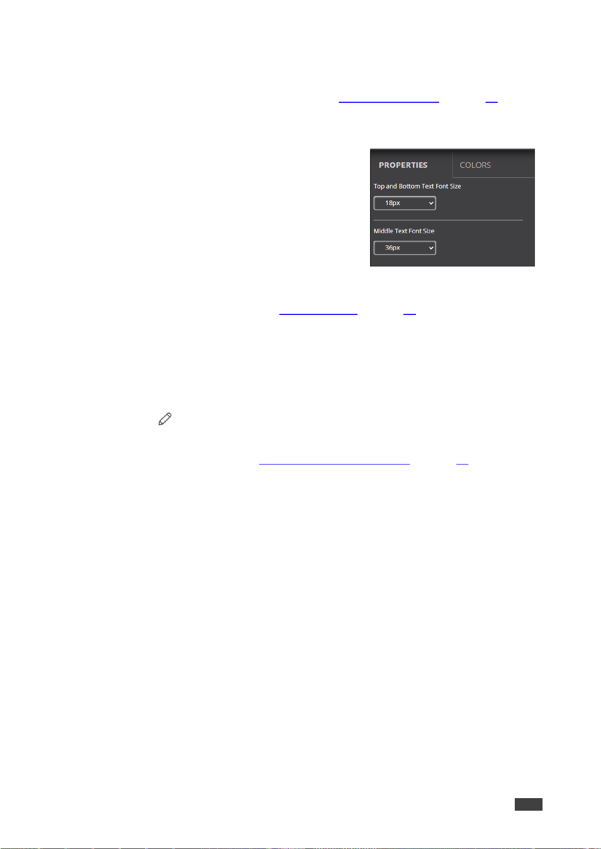
Formatting Availability
The Availability widget is a pop-up that displays meeting space availability in hours and
minutes when third party calendar is integrated (see Calendar Integration on page 60).
Format the following in PROPERTIES tab:
• Under Top and Bottom Text Font Size, select the
font size for text appearing above and below the
time.
• Under Middle Text Font Size, select the font size
for the time.
Figure 37: Availability Properties Tab
For formatting on the COLORS tab, see Formatting Text on page 31.
Editing a Screen Layout
To edit a screen layout:
1. Click Device Management > VIA Screen Editor on the navigation pane.
The Screen Editor page appears.
2. Click Edit in the row of the layout that you want to edit.
The Screen Editor window appears.
3. Edit the layout as desired (see Creating a New Screen Layout on page 28).
4. Click Save.
The screen layout edits are saved.
To save the edited screen layout as a new layout:
1. Click the arrow next to Save and select Save As.
The template name window appears.
2. Enter a new name for the layout and click Submit.
The edited layout is saved as a new layout.
Deleting a Screen Layout
To delete a screen layout:
1. Click Device Management > VIA Screen Editor on the navigation pane.
The Screen Editor page appears.
2. Select the layout that you want to delete and click Delete.
A confirmation message appears.
3. Click OK.
The selected screen layout is deleted from the VIA device and removed from the list.
Page 39

Kramer Electronics Ltd.
VIA Campus² – For Web Administrator: Gateway Management Pages
39
Exporting and Importing a Screen Layout
You can export a screen layout in the form of a screen file to use on other VIA devices.
To export a screen layout:
1. Click Device Management > VIA Screen Editor on the navigation pane.
The Screen Editor page appears.
Figure 38: Template Settings
2. Select the checkbox at the end of the row of the layout that you want to export and click
Export Templates.
A confirmation message appears.
3. Click OK.
A screen layout file (screen) is downloaded to your device.
To import a screen layout:
1. Click Device Management > VIA Screen Editor on the navigation.
The Screen Editor page appears.
2. Click Import Templates.
A file browser window appears.
3. Select the desired screen layout file and click Choose.
The selected file is uploaded to VIA Campus² and the imported layout appears in the
screen layout list.
Make sure that the exported layout file fits the resolution of the VIA device to which it is
imported.
Page 40
Kramer Electronics Ltd.
VIA Campus² – For Web Administrator: Gateway Management Pages
40
Scaling Gateway Dashboard for Large Screens
VIA Campus² enables you to enlarge the gateway dashboard on the main display when using
a large, high-resolution screen.
To scale the dashboard for large screens:
1. Click Device Management > VIA Settings on the navigation pane.
The VIA Settings page appears.
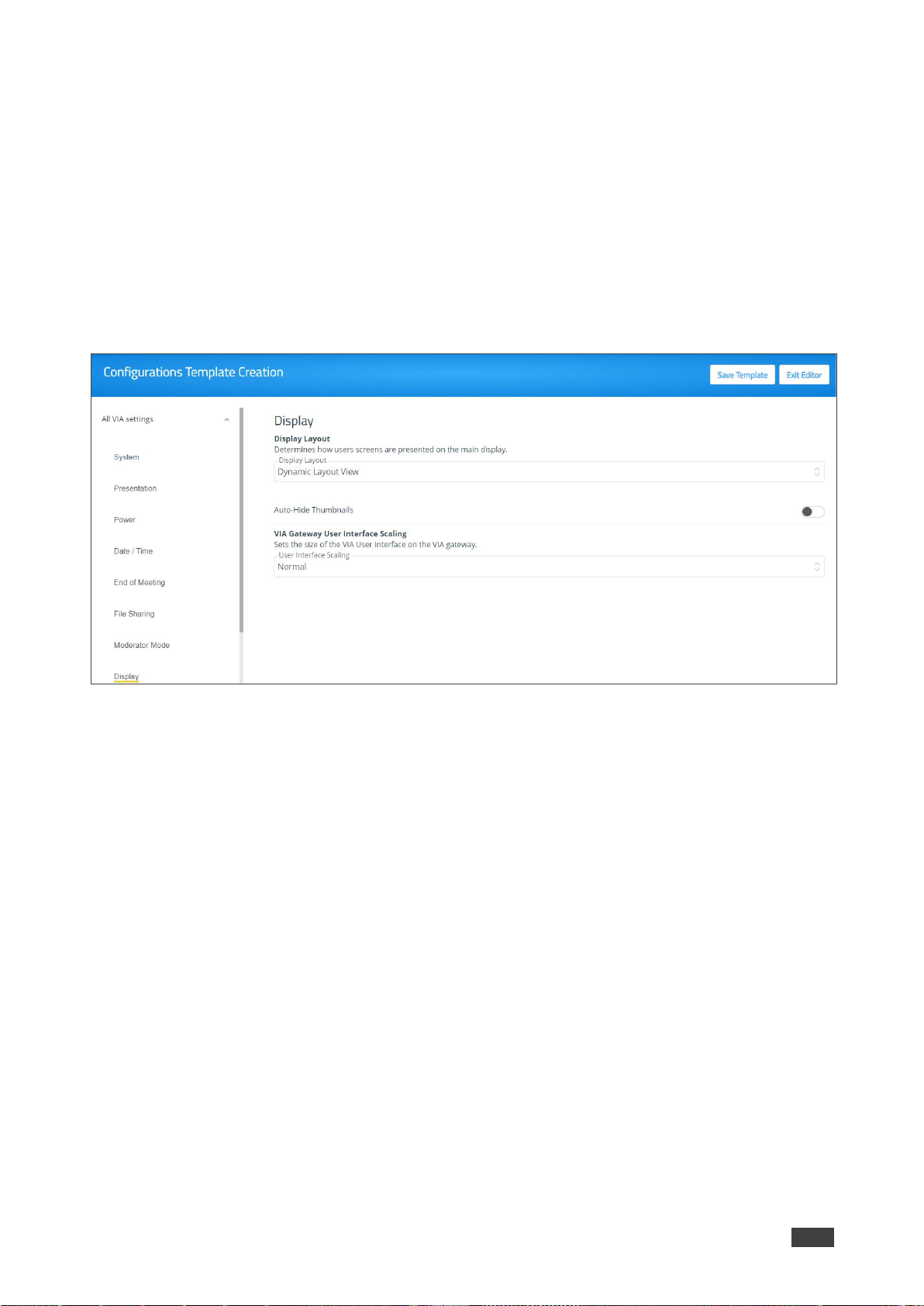
2. Click Display.
The Display tab appears.
Figure 39: Display Layout Settings
3. Under VIA Gateway User Interface Scaling, select Large from the User Interface
Scaling option box.
The dashboard is scaled for large screens.
Page 41

Kramer Electronics Ltd.
VIA Campus² – For Web Administrator: Gateway Management Pages
41
VIA Settings
VIA Campus² enables you to configure settings such as power saver, time & date, audio and
features availability and save them as part of a settings template. This enables you to define
and save different settings for different types of meetings. Just load the appropriate template
to match your needs.
To create a new gateway settings template:
1. Click DEVICE MANAGEMENT > VIA Settings on the navigation page.
The VIA Settings page appears.
Figure 40: VIA Setting Page
2. Click Create New Template; The Configurations Template Creation page appears.
Figure 41: Configuration Template Creation Page
Page 42

Kramer Electronics Ltd.
VIA Campus² – For Web Administrator: Gateway Management Pages
42
3. Enter a name for the new template and click Save Template; The new template is
saved.
4. Open the different settings pages by clicking on the navigation pane on the left and
change settings as needed.
5. As you change settings on each page, do one of the following:
a. Click Update Template to update the template without resetting and applying this
template.
Changes are saved and the template remains open for more edits.
-ORb. Click Publish & Exit to update the template and apply the newly edited template.
Changes are saved to the template, and the session resets with the new template
applied. This will take several moments, and you will need to log back into the
Gateway Management pages.
VIA Campus² enables you to configure the following types of settings that apply to the
settings template:
• System on page 43.
• Presentation on page 44.
• Power on page 47.
• Date/Time on page 48.
• End of Meeting on page 48.
• File Sharing on page 49.
• Moderator Mode on page 50.
• Audio on page 53.
• Security on page 54.
• Certificate – Manage SSL Certificates on page 55.
• NTP – Network Time Protocol on page 55.
• Recording & Streaming on page 56.
• Proxy Server on page 57.
• VIA Campus Features – Configure Client Menus on page 58.
Page 43

Kramer Electronics Ltd.
VIA Campus² – For Web Administrator: Gateway Management Pages
43
System
Configure the following settings in the VIA settings template (see VIA Settings on page 41)
that affect the overall operation of the system:
Figure 42: System Settings
• Activating System Log – Provides a log of system activities such as logins, presentation,
and VIA features usage to aid in diagnosing a problem or tracking participant usage.
(default = OFF)
To view and search Activity Logs (see Viewing and Searching System Activity Logs
on page 72).
• Activate Energy Saver Mode – Automatically send your VIA Campus² unit into sleep
mode after being inactive for a defined period of time. After activating this feature, select
the period (in minutes) from the Sleep Time field. (default = OFF)
• Quick Client Access – Display a shortcut in the bottom left corner of the main display to
open the VIA gateway dashboard. (default = ON)
• Quick Client Access - Always on Top – When ON, the VIA gateway dashboard always
appears on top of all content on the main display. (default = ON)
• API Settings Command – Select one of the following:
▪ Secure - API Commands can be sent to the VIA gateway securely over a TLS port.
▪ Non-Secure - API Commands can be sent to the VIA gateway on a non-secure,
plain-text port. Use this mode if your controller does not support TLS. (default)
• Language – Select the language for the Gateway Management pages.
Page 44

Kramer Electronics Ltd.
VIA Campus² – For Web Administrator: Gateway Management Pages
44
• Broadcast – When the user launches the Kramer VIA app, all broadcasting VIA
gateways appears automatically on the meeting spaces.
• Bluetooth – The user can see all Bluetooth enabled gateways (default = ON).
For information on how Auto Broadcast is enabled and what are its limitations, refer
to the VIA IT Deployment Guide, available for download at:
www.kramerav.com/product/VIA Campus² (click the Resources tab).
• Hide VIAAdmin at the client side – Hides the VIAAdmin user from the Participants list.
(default = OFF)
Presentation
Configure the following settings in the VIA settings template (see VIA Settings on page 41)
that affect how participants share content during a meeting:
• iOS Mirroring – The VIA gateway will act as an Apple® AirPlay receiver. If desired, type
a new Mirror Name (the name that appears when you look for AirPlay devices on your
iOS device) and select the maximum number of mirrored iOS devices that can be used
simultaneously. (default = OFF)
Figure 43: iOS Mirroring Settings
• Splash screen configuration – Web Admin can configure splash screen by
enabling/disabling the following options:
Figure 44: Splash Screen Configuration
▪ Join through Browser – Enables users that are sitting in the meeting room to join the
VIA meeting from a web browser, without downloading any software. (default = ON)
▪ Run VIA – Enables the user to run the VIA application without downloading any
software. (default = ON)
▪ Install VIA – Enables the user to install VIA client application on personal device.
(default = ON)
Page 45
Kramer Electronics Ltd.
VIA Campus² – For Web Administrator: Gateway Management Pages
45
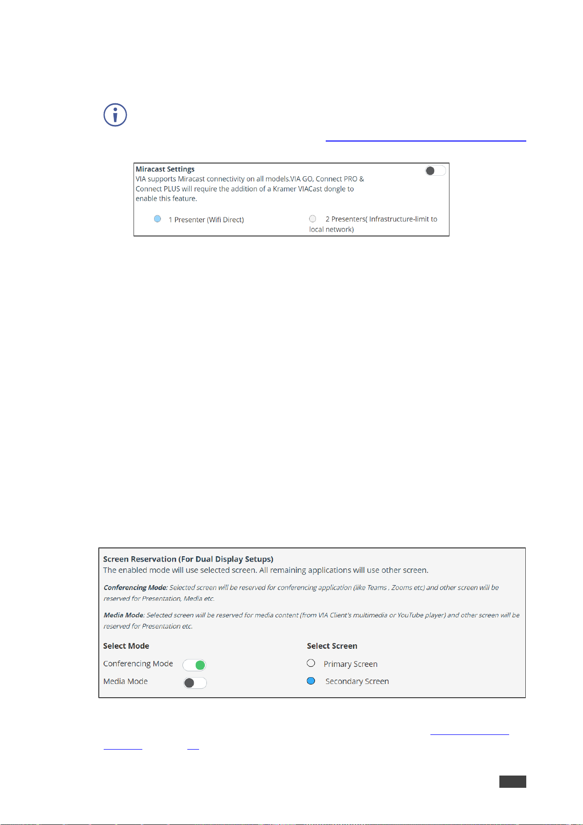
• Miracast Settings – Enables a maximum of 2 users to mirror their device screens using
the native Miracast feature on their Windows 10 laptop or Android device without using
the VIA app. (default = OFF)
If you are using the built-in Wi-Fi for Client or AP mode, a VIAcast dongle
(purchased separately) is needed to provide Miracast mirroring for meeting
participants. For more information see: www.kramerav.com/product/VIA Campus².
Figure 45: Miracast Setting Tab
• Web admin can select the following:
▪ 1 Presenter – For a single presenter using Wifi Direct. (Default = ON).
▪ 2 Presenters – For two presenters using local network.
• Reset Session – Enables all users to reset the current VIA session from an icon that
appears in the VIA task bar menu. (default = ON)
• Default Encoding for Presentation – PC & Mac clients connected to the VIA gateway
default to the encoding method selected here. (default = Auto/H264)
• Show Username – Shows presenter username while presenting (default = ON).
• Screen Reservation (For Dual Display Setup) – When two output screens are
connected to the VIA Campus² (HDMI Out and DP Out), you can set one screen to
display the conferencing (the source is a shared screen or app) and the other to display
the media source that is being streamed.
By default, the first device detected will be set as the Primary Screen, but this can be
redefined on the Gateway itself, in the Gateway Dashboard, Settings Menu (login
required). You can also set both displays to show the same content. After updating
remember to click Update Template and then Publish & Exit.
Figure 46: Screen Reservation Settings
For detailed instructions on configuring dual display setup, see Configuring dual
displays on page 13.
Page 46

Kramer Electronics Ltd.
VIA Campus² – For Web Administrator: Gateway Management Pages
46
Dual display use requires that the secondary screen is set as an extension of the
primary screen. This definition is made on the Main Screen of the VIA Campus²
using the Gateway Dashboard.
Instructions on using the Gateway Dashboard are available in Configuring Dual
Displays on page 81.
• Auto DND – The Present Privately (DND - Do Not Disturb) feature allows only the active
presenter to present and prevents all other participants from presenting. Auto DND
activates DND when a user starts presenting from their device (default = OFF).
Figure 47: DND Setting Tab
• Do Not Disturb – After clicking the Present button, the full screen presenter can enable
or disable DND. (default = OFF)
Figure 48: VMD Settings
• Local Annotation – Users can annotate locally on their device while using the View
Main Display feature. If this feature is not activated, users can only view, but not
annotate. (default = ON)
• Public Annotation – Users can start public annotation while using the View Main
Display feature. When public annotation is started, the user’s local annotation appears
live on the main display, and the whiteboard tools are shown. (default = ON)
• Presentation Always in full Screen – Only one user at a time can present. When a
new presentation is started, the current presentation stops. (default = OFF)
• Auto Disconnection – VIA Campus² will automatically disconnect the user when their
connection signal weakens:
▪ Deviation – The change in signal strength that will lead to disconnection.
▪ Attempts – The number of reconnect attempts before disconnecting.
Page 47

Kramer Electronics Ltd.
VIA Campus² – For Web Administrator: Gateway Management Pages
47
Power
Configure the following energy-saving automatic power settings in the VIA settings template
(see VIA Settings on page 41). Power settings works according to the time zone that the user
configures in Date/Time settings (see Date/Time on page 48):
Figure 49: VIA Power Settings
• Auto Power Off Timing – Set a time for VIA Campus² to automatically shut down each
day.
• Auto Reboot Timing – Set a time for VIA Campus² to automatically reboot each day.
Page 48
Kramer Electronics Ltd.
VIA Campus² – For Web Administrator: Gateway Management Pages
48
Date/Time
Configure the following settings in the VIA settings template (see VIA Settings on page 41)
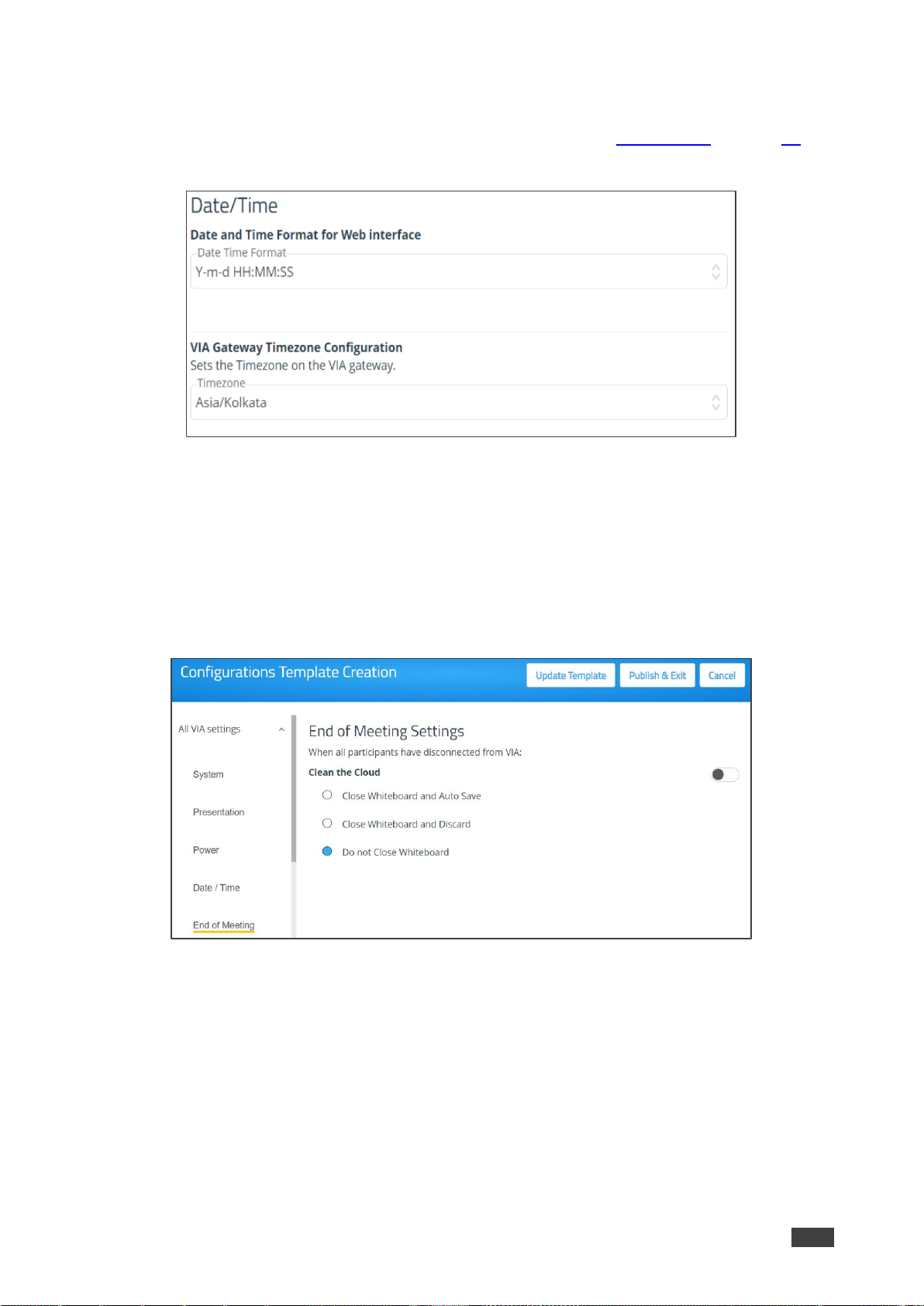
that define the date and time displayed on the Gateway Management Pages:
Figure 50: VIA Date/Time Settings
• Date and Time Format for Web Interface – Select the format for displaying the date and
time on the Dashboard page.
• VIA Gateway Timezone Configuration – Select the time zone for VIA Campus².
End of Meeting
Select what happens when all participants have disconnected from a VIA meeting:
Figure 51: End of Meeting Settings
• Clean the Cloud: Enable one of the following Whiteboard options:
▪ Close Whiteboard and Auto Save – Closes the Whiteboard on the main display
and saves the current page to the VIA cloud.
▪ Close Whiteboard and Discard – Closes the Whiteboard on the main display and
discards the current page.
▪ Do not Close Whiteboard – The current whiteboard page remains on the main
display.
Page 49
Kramer Electronics Ltd.
VIA Campus² – For Web Administrator: Gateway Management Pages
49
File Sharing
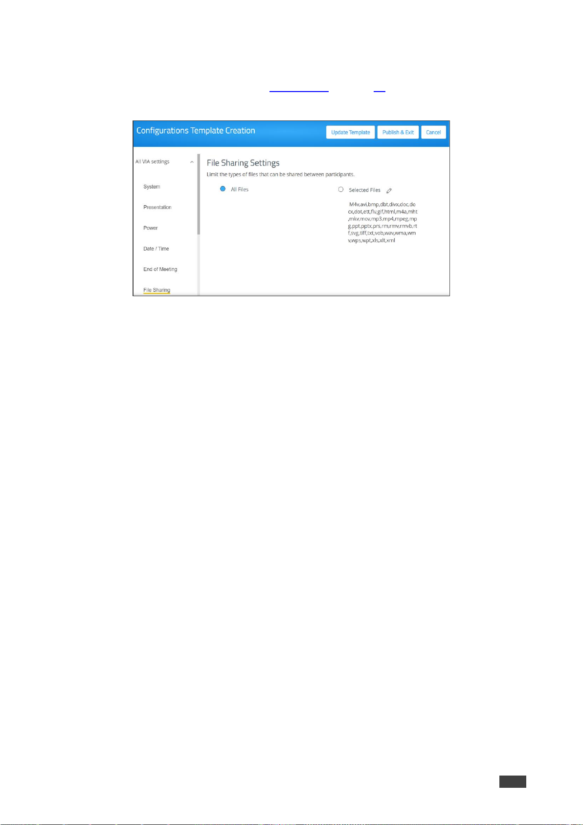
Select in the VIA settings template (see VIA Settings on page 41) one of the following options
for defining the type of files that can be shared between participants:
Figure 52: Files Sharing Settings
• All Files – Share any type of file between participants.
• Selected Files – Limit file types shared between participants to the defined list. Click the
edit icon to add or remove file types from the allowed list.
Page 50

Kramer Electronics Ltd.
VIA Campus² – For Web Administrator: Gateway Management Pages
50
Moderator Mode
Moderator Mode settings define who can be a meeting moderator and what features are
active for the moderator.
When Moderator Mode is activated, the Moderator icon appears on the VIA User Dashboard
of eligible participants (see Moderating - Controlling the Meeting on page 100) .
Figure 53: Moderator Mode Setting
1. Select who can become a moderator:
▪ Database Based – Only users with accounts created in VIA Campus² database can
moderate (see User Management on page 19).
▪ Active Directory – Only users defined in the Active Directory can moderate
(see Configuring Active Directory Moderator Mode on page 51).
▪ Basic – Anyone can moderate. To require a password before becoming moderator,
(see Security on page 54).
Configure “Database based” or “Active Directory” in moderator mode to define who
can join the VIA meeting.
2. Moderator checkboxes:
▪ Moderator can enable/disable Chat feature during a session.
▪ Allow Participants to confirm start of Presentation – Attempts to screen share
must be approved by the moderator.
▪ Wait for Moderator to Start Session – The VIA session does not start until a
moderator joins the meeting. User dashboard features are grayed out and a
message appears on the main display.
This feature is not available in Basic Moderator Mode.
Page 51
Kramer Electronics Ltd.
VIA Campus² – For Web Administrator: Gateway Management Pages
51
Configuring Active Directory Moderator Mode
Active Directory users can be imported into VIA Campus² Gateway Management Pages.
The Active Directory must be organized into two sets of users: one that has permission to
become moderator and one that does not have moderator permission. When using Active
Directory, only users who are in the directory can join a VIA meeting.
Active directory mode enables displaying user’s First name and Last name while using VIA
features such as “Chat”, “Present”, “File transfer”, “Enable DND”, “Mouse hover”, “Activity
Log”, etc.
You can use Groups or OUs (Organizational Units) to divide the moderator and
participant/non-moderator set of users.
Do not use Groups or OUs that have any employee in common. If there is overlap of users in
your existing Groups, you will have to create new Groups for this purpose.
To configure Active Directory Moderator Mode:
1. On the VIA setting Template, select Moderator Mode tab (see Moderator Mode
on page 50).
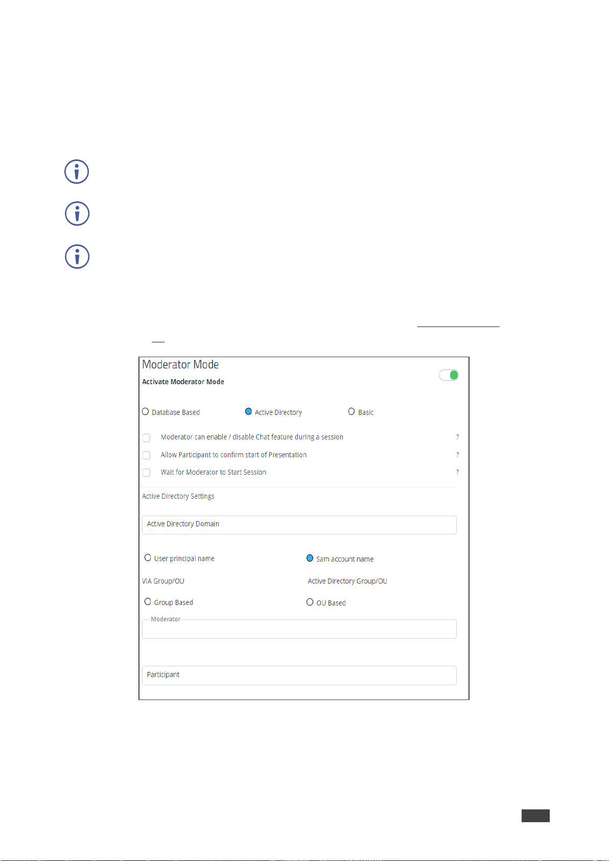
Figure 54: Active Directory Setting
2. Click the Activate Moderator Mode switch and select Active Directory.
The Active Directory settings appear.
3. In the Active Directory Domain text box, enter the Active Directory domain name.
Page 52

Kramer Electronics Ltd.
VIA Campus² – For Web Administrator: Gateway Management Pages
52
4. Select User principal name or Same account name.
5. Select the Group Based or OU Based radio button as per your Active Directory
configuration.
6. Based on the above selection, type the name of the Moderator and Participant
Group/OU in their respective boxes.
7. Login the gateway dashboard settings (see Logging in to the Gateway Dashboard
on page 76) and select LAN settings.
8. Click on the Host Configurator.
The Host configuration page appears.
Figure 55: Host Configuration Page
9. On the Host Configuration page, enter the Active Directory server IP >> Space >>
Active Directory Domain Name and click Save.
Active Directory Moderator Mode is configured.
VIA Campus² does not discover and connect to the Active Directory; rather it relies on you to
correctly enter the details. If there is a typographical error in any of the fields, the users
(Moderators and Participants) cannot log in.
For further details, refer to “VIA Integration into DNS and Microsoft Active Directory” white
paper.
Page 53

Kramer Electronics Ltd.
VIA Campus² – For Web Administrator: Gateway Management Pages
53
Audio
Configure the following audio related settings in the VIA settings template (see VIA Settings
on page 41):
Figure 56: Audio Settings
• VIA Gateway Audio Input – Set the audio input device for the VIA Campus².
• VIA Gateway Audio Output – Select the audio output device connected to the Gateway.
• Default Audio Level – After rebooting the unit, resetting a session, or returning to a
meeting after all users have logged off, the volume returns to this defined level.
See also Audio – Enabling Audio for VIA Versa Video Conferencing on page 110.
Page 54
Kramer Electronics Ltd.
VIA Campus² – For Web Administrator: Gateway Management Pages
54
Security
Configure the following settings in the VIA settings template (see VIA Settings on page 41)
that affect login security for the Gateway Management Pages and for VIA meetings:
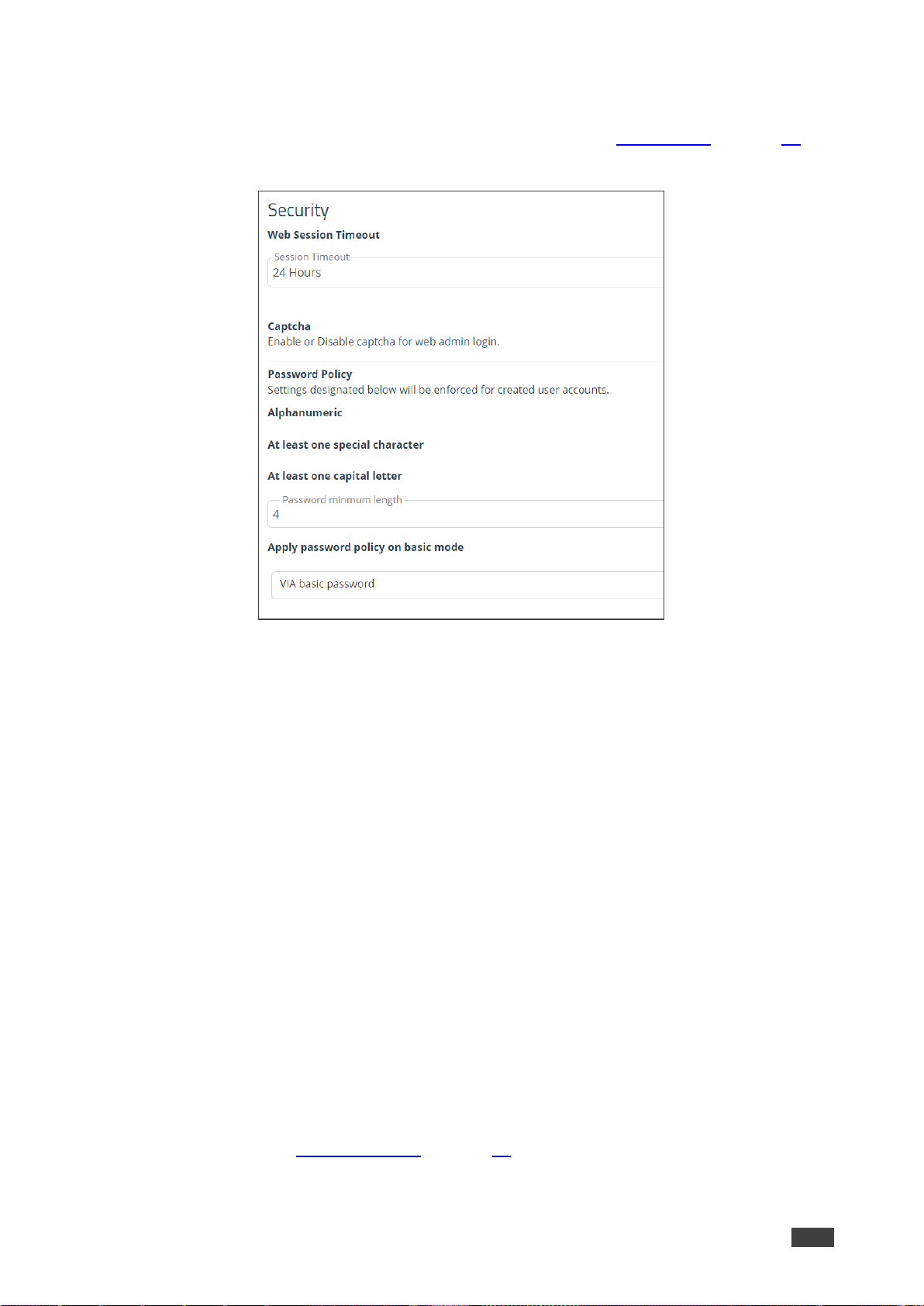
Figure 57: VIA Security Settings
• Web Session Timeout – Select the amount of idle time before an administrator is
automatically logged out of the Gateway Management Pages.
• Captcha – Turn ON or OFF the captcha challenge when logging into the Gateway
Management Pages.
The following Password Policy settings affect new user accounts for logging into the Gateway
Management Pages and joining a VIA meeting:
• Alphanumeric – Require at least one letter and one number to be included in a user
password.
• At least one special character – Require at least special character (like: !, @, #) to be
included in a user password.
• At least one capital letter – Require at least one capital letter to be include in a user
password.
• Password minimum length – Define a minimum number of characters for a user
password.
• Apply password policy on basic mode – Require all the above rules when creating
the Basic mode password (below).
• VIA basic password – Define the password needed to become moderator when in
Basic mode (see Moderator Mode on page 50). To remove the password requirement,
clear the password field.
Page 55

Kramer Electronics Ltd.
VIA Campus² – For Web Administrator: Gateway Management Pages
55
Certificate – Manage SSL Certificates
A custom SSL certificate can be uploaded to VIA Campus², to better provide for the security
needs of your organization.
To prevent damage to the system, make sure you upload files that can be used by the
system. If you are unsure of how to use this feature, contact technical support.
For information on how to create a certificate, see Creating an SSL Certificate for VIA,
available at: VIA Campus²www.kramerav.com/product/VIA Campus²
After obtaining your certificate, install it on your VIA device.
The uploaded files must stay in the format of “server.crt” & “server.key”.
To upload an SSL certificate:
1. On the Certificate tab in the VIA settings template (see VIA Settings on page 41), copy
and paste the web server certificate.
The web server certificate is uploaded.
Do not upload the key file until the certificate file is finished uploading.
2. Copy and paste the key file; The key file is uploaded.
NTP – Network Time Protocol
An NTP (Network Time Protocol) server can synchronize the time on VIA Campus².
To add an NTP server:
Figure 58: NTP Server Settings
• In the NTP tab in the VIA settings template (see VIA Settings on page 41), enter the
NTP server address and click Add.
The new NTP server is saved and appears in the NTP Server table.
To edit an NTP server name, click the icon in the Edit column.
To delete an NTP server name, click the icon in the Delete column.
Page 56

Kramer Electronics Ltd.
VIA Campus² – For Web Administrator: Gateway Management Pages
56
Recording & Streaming
VIA Campus² enables you to record all activity on the main display during the course of a
meeting (see Recording a Meeting on page 108). Before using the recording feature, you
must activate it in the Gateway Management Pages.
To activate the recording feature:
1. On the VIA Settings Template (see VIA Settings on page 41), select the Recording &
Streaming tab:
Figure 59: Recording & Streaming Settings
2. Enable the Activate Recording switch (it is green when switched on).
3. Select one of the following locations to save the meeting recordings:
▪ System Default – Default location on the VIA hard drive. Recordings are retrieved
from the Recording > Recording List page.
▪ USB – External drive connected to the USB connector on the VIA Campus².
▪ Cloud – VIA Cloud,
The recording feature is activated.
Streaming
VIA Campus² can stream all main display activity to the following types of receivers:
• Another VIA Unit.
• Computer (Windows, Linux, Mac) which can run VLC player.
Page 57

Kramer Electronics Ltd.
VIA Campus² – For Web Administrator: Gateway Management Pages
57
Creating a Unicast Streaming URL
To create a unicast streaming URL:
1. Find the IP address of the receiver using one of the following methods:
▪ Windows computers – Type ipconfig in the Command Prompt.
▪ Mac computers – Type ipconfig in the Terminal.
▪ Another VIA unit – Use the room name that appears on the Home screen.
2. Use any allowed port number from 1 – 65536.
3. Use the following format for a UDP URL:
udp://<IP address>:<port number>/.
Example: For a receiver with an IP address of 192.168.100.123 and an allowed port of
2234, the UDP URL is:
udp://192.168.100.123:2234/
OR
Use the following format for an RTP URL:
<rtp>:<ip>:<port>
Feeding Receiver Information to VIA Campus²
The receiver information must be fed to VIA Campus² before streaming can begin.
To feed receiver information to VIA Campus²:
1. In the Streaming tab in the VIA settings template (see VIA Settings on page 41), paste
the receiver URL in the Streaming URL text box. The URL must be in the format
explained in Creating a Unicast Streaming URL on page 109.
2. Click the Streaming switch ON.
Streaming is activated, and the Streaming URL field is disabled.
To change the receiver URL while streaming, click the Streaming switch OFF, paste
the new URL in the box and click the Streaming switch ON again.
Proxy Server
A proxy server can handle the URLs used for VIA meetings (for example, Youtube URLs used
for the Youtube player feature) and for firmware downloads.
To define a proxy server:
• In the Proxy Server tab in the VIA settings template (see VIA Settings on page 41), enter
your proxy server parameters.
• After entering the parameters, click Test Proxy Server to verify that all parameters were
entered correctly and that a connection has been established.
Page 58

Kramer Electronics Ltd.
VIA Campus² – For Web Administrator: Gateway Management Pages
58
VIA Campus Features – Configure Client Menus
Use these options to reorganize the
VIA Campus² user menu and hide
menu options.
The following menus can be changed:
• Gateway Features – The menu
shown on the main display.
• Client Features – The menu
shown on participants’ laptops and
tablets.
• Mobile Features – The menu
shown on participants’
smartphones.
Figure 60: VIA Campus² Features Tab
To organize the menus shown to
participants:
1. Scroll down on the Configurations
Template Creation navigation pane
and click Gateway Features or
Client Features or Mobile
Features.
2. Click and drag feature icons to a
new position as needed.
3. Enable or disable the features by
clicking the switch (green=
enabled).
Hidden (disabled) features move to
the bottom of the list.
Changes are reflected in the menu
after the new template is updated
and published.
Figure 61: VIA Campus² Features Tab
Page 59

Kramer Electronics Ltd.
VIA Campus² – For Web Administrator: Gateway Management Pages
59
Display Controller
Use the VIA Campus² device to control a display screen that is connected to the same
network.
This feature enables you to configure one of the following actions:
• When the first person joins the meeting, the main display powers ON and when the last
person logs out of the meeting, the main display powers OFF.
• Send a switch HDMI Input command, to toggle between the VIA input and any other
device connected to the same display.
To configure your VIA Campus² as a display controller:
1. Connect the display to be controlled to the same network as your VIA Campus².
2. Click Device Management > Display Controller on the navigation pane.
The Display Controller page appears.
Figure 62: Display Controller Settings
3. Click the Activate Control switch.
4. Enter the Display IP address and Display Control Port of the display screen to be
controlled.
5. For Command 1, enter the command to send when someone first joins a meeting (for
example, power ON the display).
6. For Command 2, enter the command you want the VIA to send when the last participant
logs out of the meeting (for example, power OFF display).
7. Select ASCII or HEX to define command format accepted by your display.
Refer to the User Manual for your display for the correct format of the commands.
Configuring your VIA Campus² as a display controller is complete.
Page 60

Kramer Electronics Ltd.
VIA Campus² – For Web Administrator: Gateway Management Pages
60
Calendar Integration
VIA Campus² enables you to display scheduled meeting information on the main display
home screen. VIA automatically retrieves information about meetings scheduled in the room
where the VIA device resides. This feature is available for a room that has been added in
Office 365® Admin Center, Microsoft Exchange® or in Google® Admin Console for G Suite®.
Before configuring this feature in the VIA Gateway Management Pages, you must add the
room in either Office 365 Admin Center, Microsoft Exchange or Google Admin Console
for G Suite.
Integrating an Office 365 Calendar
To integrate your Office 365 Calendar with VIA Calendar:
1. Click Device Management > Calendar on
the navigation pane.
The Calendar Account displays with Office
365 Basic Auth selected.
2. Select Office 365 Basic Auth from the
Calendar Type drop down.
3. Enter the following for the room where this
VIA gateway resides:
▪ Username – Email address assigned to
the room.
▪ Password – Password associated with
the room Username.
4. Select a Permission Type for the user:
None, Impersonation, Delegate.
Figure 63: Third Party Calendar Configuration Page
• Impersonation - Gives the device full access to the calendar (less secure).
• Delegate – You will need to specify which parts of the calendar can be used.
5. In Resource Calendar, enter a calendar name to identify the created calendar.
Enabled when Impersonation or Delegate are selected.
6. Click Test & Save to test if the details entered are correct.
7. Configure your calendar in Formatting Calendar on page 36.
Page 61

Kramer Electronics Ltd.
VIA Campus² – For Web Administrator: Gateway Management Pages
61
Integrating Microsoft Exchange
When a resource mailbox (e.g., a meeting space) is created, the Exchange® administrator can
synchronize with the mailbox to be none, an Impersonation, or a Delegate.
To integrate Microsoft Exchange with VIA Calendar:
1. Click Device Management > Calendar on the navigation pane.
The Calendar Account displays.
2. Select the Activate Calendar checkbox.
3. Select MS Exchange from the Calendar Type drop down.
The MS Exchange controls appear.
4. Enter the server URL.
5. Select the relevant version of Microsoft Exchange.
6. Enter the following for the meeting space where this VIA gateway resides:
▪ Username – Email address assigned to the meeting space.
▪ Password – Password associated with the meeting space Username.
7. Select a Permission Type for the user: None, Impersonation, Delegate.
▪ Impersonation - Gives the device full access to the calendar (less secure).
▪ Delegate – You will need to specify which parts of the calendar can be used.
8. Resource Calendar is enabled when Impersonation or Delegate are selected;
Enter a calendar name to identify the created calendar.
9. Click Test & Save to test if the details entered are correct.
Microsoft Exchange is integrated with VIA Calendar.
Integrating Google Calendar
To integrate your Google Calendar with VIA Calendar:
1. Click Device Management > Calendar on the navigation pane.
The Calendar Account displays.
2. Select Google from the Calendar Type drop down.
The Google Calendar controls appear.
3. Click Click here to get code; Google sign in page appears.
4. Sign-in with the Google account where the shared space calendar was created.
5. Allow access to VIA-Calendar; An integration code appears.
6. Copy the integration code from the Google sign in page and paste it into the Step 2 field
on the VIA Calendar page.
7. Click Get Calendar.
8. In the Select the calendar field, select the calendar associated with the room.
9. Click Associate; Your Google Calendar is integrated with VIA Calendar.
Page 62
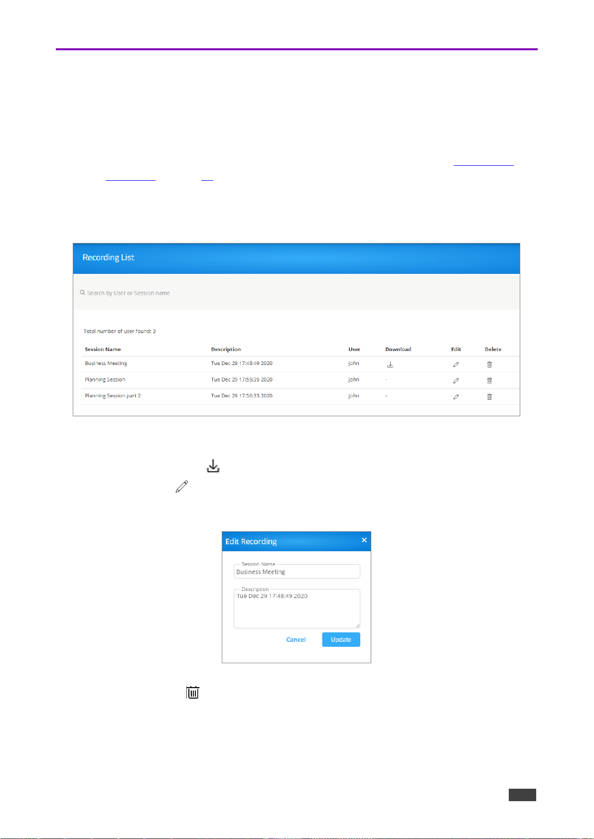
Kramer Electronics Ltd.
VIA Campus² – For Web Administrator: Gateway Management Pages
62
Recording – Managing Saved Recordings
Retrieving Recordings Saved on the Device
VIA Campus² enables you to search, download and edit meeting recordings saved to the
device.
• To activate the ability to record meetings and set the save location, see Recording &
Streaming on page 56.
To manage meeting recordings:
1. Click Recording on the navigation pane; The Recording List appears.
Figure 64: Recording List Page
2. Search for a User or Session name into the Search box.
3. Click the Download icon to download a recording.
4. Click the Edit icon to rename a recording file or update its description.
The Edit Recording pane for the relevant recording appears.
Figure 65: Edit Recording Screen
5. Click the Delete icon to permanently remove a selected recording.
Page 63

Kramer Electronics Ltd.
VIA Campus² – For Web Administrator: Gateway Management Pages
63
Digital Signage
For VIA devices sold before June 1st, 2019, Digital Signage is an optional feature available
through separate licensing and pricing. Contact your local Kramer office for more details.
VIA Campus² Digital Signage displays dynamic content and information on the main display
when there is no meeting in progress. Use a predefined template or create your own display
layout with up to three frames of content that appear simultaneously. Then, schedule the
content to run automatically at specific dates and times.
Configuring digital signage includes the following steps:
• Creating and Uploading Digital Signage Media on page 63.
• Creating Custom Digital Signage Templates on page 67.
• Configuring a Digital Signage Campaign on page 69.
• Scheduling Digital Signage Campaign on page 70.
• Adding Fonts to Digital Signage on page 71.
Creating and Uploading Digital Signage Media
VIA Campus² enables you to create a library of media content to be displayed through the
digital signage feature. The types of media that can be displayed are:
• Scroller – A custom text message that scrolls across the screen.
• RSS – Live RSS feed.
• Web URL – A live web page or HTML file.
• Media – Static image (jpg, jpeg, bmp, gif, png) or Video (avi, mpeg, wmv, mpg, mov,
vob, mkv, mp4, m4v).
To create and upload digital signage media:
1. Click Digital Signage > Manage Content on the navigation pane.
The Manage Content page appears.
Figure 66: Digital Signage: Manage Content Page
Page 64

Kramer Electronics Ltd.
VIA Campus² – For Web Administrator: Gateway Management Pages
64
2. Create and upload media, as required:
▪ Creating Scrolling Text on page 64.
▪ Adding RSS Feed on page 65.
▪ Adding Web URL on page 65.
▪ Uploading Media Files on page 66.
Creating Scrolling Text
To create scrolling text:
1. On the Manage Content page, click Add
Content.
The Add Content pane appears with the
Scroller tab open.
2. Type the text to be displayed in the box.
3. Type a name for the scroller in the Scroll
Name text box.
4. Set the scroll speed.
Set the scroll speed to Zero, to create a
static text display that does not scroll.
5. Set the font parameters.
To add a font, click Upload Font or
see Adding Fonts to Digital Signage
on page 71 .
Figure 67: Scrolling Text Setting Tab
The following variables can be entered into the text field:
• #airplayname# – Displays the airplay name.
• #roomname# – Displays the room name/code for joining into the meeting.
• #appass# – Displays the Access Point password.
• #apname# – Displays the Access Point name.
• #ipaddress1# –Displays the IP address for the primary network.
• #ipaddress2# – Displays the IP address for the second network, if in use.
6. Set the background color.
7. Click Create.
The Scroller is created and added to the Existing Media table (in the Manage Content
page).
Page 65
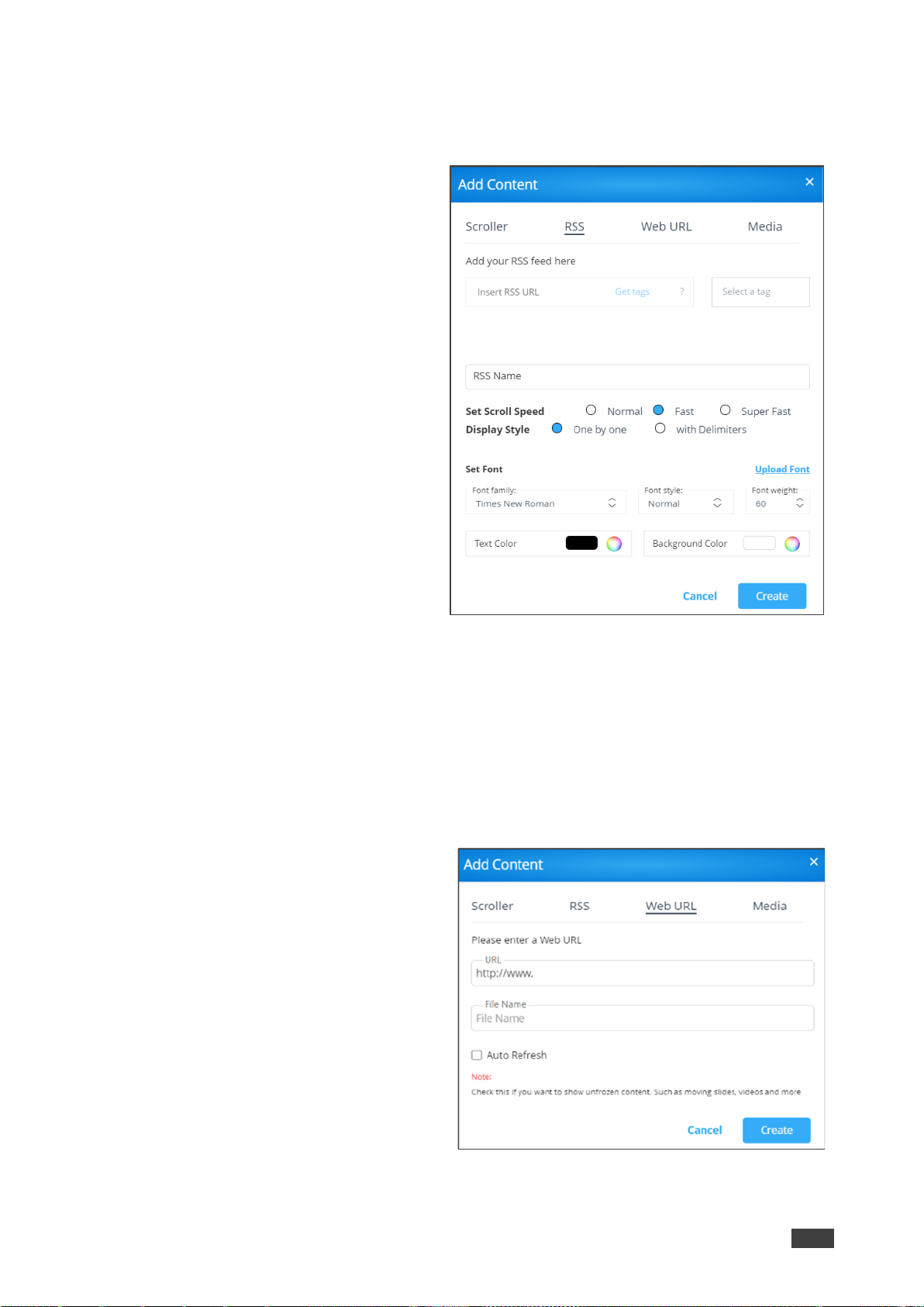
Kramer Electronics Ltd.
VIA Campus² – For Web Administrator: Gateway Management Pages
65
Adding RSS Feed
To add an RSS feed:
1. On the Manage Content page, click
Add Content.
The Add Content pane appears with
the Scroller tab open.
2. Click RSS.
The RSS tab appears.
3. Enter the RSS feed’s URL address.
4. Click Get tags and select the required
tag from the Select a tag drop-down
list.
5. In the RSS Name field, enter a name
for the RSS feed that will appear in the
Existing Media table.
6. Under options, select the speed,
display style, font settings and
background color for the RSS feed.
7. Click Create.
The new RSS feed is added and
appears in the Existing Media table.
Figure 68: RSS Setting Tab
Adding Web URL
Add the URL of an existing web page or use a third-party solution (for example, Google
Slides) to publish a presentation to the web and add the URL of the presentation.
To add a web URL for digital signage:
1. On the Manage Content page, click Add
Content: The Add Content pane
appears with the Scroller tab open.
2. Click Web URL; The Web URL tab
appears.
3. Select the Auto Refresh checkbox to
display a URL with dynamic content.
OR
Clear the Auto Refresh checkbox to
display a URL as a static page.
4. Type the URL address and File Name
and click Create: The new URL is added
and appears in the Existing Media table.
Figure 69: Web URL Setting Tab
Page 66

Kramer Electronics Ltd.
VIA Campus² – For Web Administrator: Gateway Management Pages
66
Uploading Media Files
To upload media files:
1. On the Manage Content page, click Add Content.
The Add Content pane appears with the Scroller tab open.
2. Click Media.
The Media tab appears.
Figure 70: Media Settings
3. Click Browse File.
A file browser appears.
4. Select an image or video file and click Upload.
The file is added and appears in the Existing Media table.
Page 67

Kramer Electronics Ltd.
VIA Campus² – For Web Administrator: Gateway Management Pages
67
Creating Custom Digital Signage Templates
Templates dictate the layout of the digital signage content. Up to 3 frames of content can be
displayed at once. VIA Campus² enables you to use predefined templates and to create
custom templates.
To create a custom digital signage template:
1. Click Digital Signage > Template Manager on the navigation pane.
The Template Manager page appears with Pre-Defined Templates tab open.
Figure 71: DSS Template Setting Page
The Pre-Defined Templates tab explains all the pre-defined templates that are available
when you create a campaign
2. Click Custom Templates; The Custom Templates tab appears.
3. Click Add Template; The Add Template pane appears.
Figure 72: Add Template Pane
Page 68

Kramer Electronics Ltd.
VIA Campus² – For Web Administrator: Gateway Management Pages
68
4. Type a name for the new template in the Template Name text box.
5. Click and drag one of the frames into preview box.
The frame parameters for the frame appear below the preview.
6. Click and drag the box to move and resize it.
7. Select the Audio checkbox to play audio from the selected frame.
Only one frame can include audio.
8. Repeat steps 5–9 to add up to two more frames.
The layering order of the frames, from bottom to top is Frame 1, Frame 2, Frame 3.
9. Click Save.
The new template is added and appears in the Saved Templates table on the Custom
Templates tab.
Click the Preview icon for a template to see a preview.
Click the Edit icon to open the template builder screen and edit the selected template.
Templates that are In Use (i.e. they have been used to configure a campaign
(see Configuring a Digital Signage Campaign on page 69) cannot be edited.
Click the Delete icon to delete the selected template.
Page 69

Kramer Electronics Ltd.
VIA Campus² – For Web Administrator: Gateway Management Pages
69
Configuring a Digital Signage Campaign
A Digital Signage Campaign defines what is displayed in each frame of a digital signage
template layout.
To configure a digital signage campaign:
1. Click Digital Signage > Campaign Editor on the navigation pane.
The Create Campaign page appears.
Figure 73: Campaign Editor
2. Click Add Campaign; The Campaign Editor appears.
Figure 74: Campaign Editor Pane
3. Click a System or Custom Template; The template appears in the preview box.
4. Click and drag one or more elements from the Content List into each frame.
The active frame turns blue, and a list of the content items appears below the preview.
5. Set a Playlength for relevant items of content in the frame.
Videos and other content that have a specific time length do not need to be set.
6. Click Save; A message appears.
7. Enter a name for your Campaign and click Ok.
The Campaign is configured, and it appears on the Create Campaign page.
Page 70

Kramer Electronics Ltd.
VIA Campus² – For Web Administrator: Gateway Management Pages
70
Scheduling Digital Signage Campaign
VIA Campus² enables you to schedule when a digital signage campaign is displayed.
To schedule a digital signage campaign:
1. Click Digital Signage > Schedule Campaign on the navigation pane.
The Schedule Campaign page appears.
Figure 75: Schedule Campaign Page
2. Click Add Schedule; The Scheduling pane appears.
Figure 76: Schedule Pane
3. Select a Campaign to schedule.
4. Set a start date, end date, and hours.
5. Enter a name for the Campaign.
6. Click Schedule.
The Campaign is scheduled, and it appears on the Schedule Campaign page.
Page 71
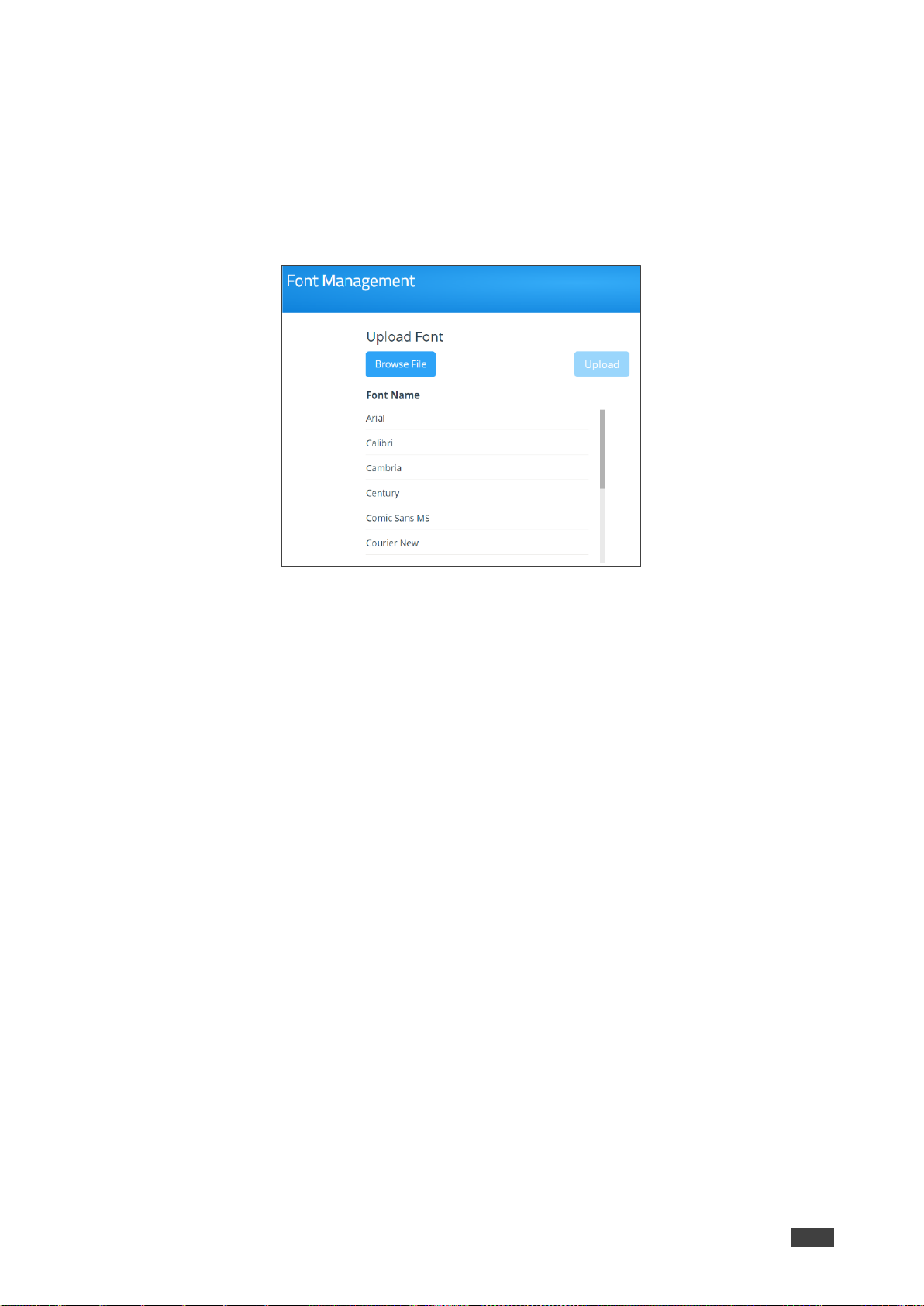
Kramer Electronics Ltd.
VIA Campus² – For Web Administrator: Gateway Management Pages
71
Adding Fonts to Digital Signage
VIA Campus² enables you to upload fonts for digital signage.
To add new fonts to Digital Signage:
1. Click Digital Signage > Font Management on the navigation pane.
The Font Management page appears.
Figure 77: Font Management Page
2. Click Browse File.
A file browser appears.
3. Open the relevant font file and click Upload.
The new font is installed on VIA Campus² and can be used for Digital Signage.
Page 72

Kramer Electronics Ltd.
VIA Campus² – For Web Administrator: Gateway Management Pages
72
Reports – Activity Logs
Viewing and Searching System Activity Logs
The VIA Campus² embedded web pages can activate a log of activities such as logins,
presentations and feature use for problem diagnosis or tracking participants.
To activate system activity logs, see System on page 43.
There are two types of system logs available for viewing and search:
• Gateway Activity Log – Shows activity of the meeting participants.
• Webadmin Activity Log – Shows activity of the Gateway and Gateway Settings
embedded web pages.
To view and search the system activity logs:
1. Click Reports > Webadmin Activity Log / Gateway Activity Log on the navigation
pane; The Webadmin Activity Log / Gateway Activity Log page appears.
Figure 78: Web Activity Log Page
2. Select the date range of the log entries to be displayed.
3. Enter a search term and press the Enter key.
The filtered search results appear in the table at the bottom of the page.
Click Export to PDF or Export to CSV to save a file of the log table on your computer.
Page 73

Kramer Electronics Ltd.
VIA Campus² – For Web Administrator: Gateway Management Pages
73
Utility
Maintain your VIA Campus² using the following utilities:
• Update Firmware on page 73.
• DSS License on page 74.
• Maintenance - Resetting Default Settings on page 75.
Update Firmware
The upload process and then the unit reboot may take a few minutes.
To update your VIA Campus² firmware:
1. Click Utility > Update Firmware on the navigation pane; The Update Firmware page
appears.
Figure 79: Update Firmware Page
2. If you don’t already have an update file saved on your computer, click Check for
Update, to locate and download a file.
3. Click Browse File to select the firmware update file.
4. Click Upload to upload the new firmware to the unit and update the firmware.
5. The unit reboots after the new firmware is installed.
To verify the update, view the current firmware version on the upper right corner of the
dashboard Participants tab.
Page 74

Kramer Electronics Ltd.
VIA Campus² – For Web Administrator: Gateway Management Pages
74
DSS License
To upload your VIA Campus² Digital Signage license:
1. Select UTILITY > DSS License on the navigation pane.
The Digital Signage License Management page appears.
Figure 80: DSS Signage License Management Page
2. Click Browse File; A file browser opens for you to select the relevant license file.
3. Click Upload; The license is installed on VIA Campus² and license information appears
at the bottom of the page.
If a Digital License is already installed on your device, the name of the license appears on the
bottom of the page.
1. Select UTILITY > DSS License on the navigation pane; The VIA License page appears.
2. Click Activate License.
The VIA Campus² digital signage license is activated, and license information appears
at the bottom of the page.
Page 75

Kramer Electronics Ltd.
VIA Campus² – For Web Administrator: Gateway Management Pages
75
Maintenance - Resetting Default Settings
To Reset VIA Campus² to factory defaults.
Resetting Calendar Settings removes the calendar settings from the unit and credentials will
be required to renew synchronization to your calendar.
To reset default settings:
1. Click Utility > Maintenance on the navigation pane.
The FACTORY RESET tab in the Maintenance page appears.
Figure 81: Factory Reset Page
2. Select the default configurations you would like to reset from the list or click Select All to
select all settings.
3. Click Apply.
Default settings reset after reboot.
To reset Logs:
1. Click Utility > Maintenance on the navigation pane.
The Factory Reset tab on the Maintenance page appears.
2. Select the Logs checkbox.
3. Click Apply.
Logs resets after reboot.
Page 76
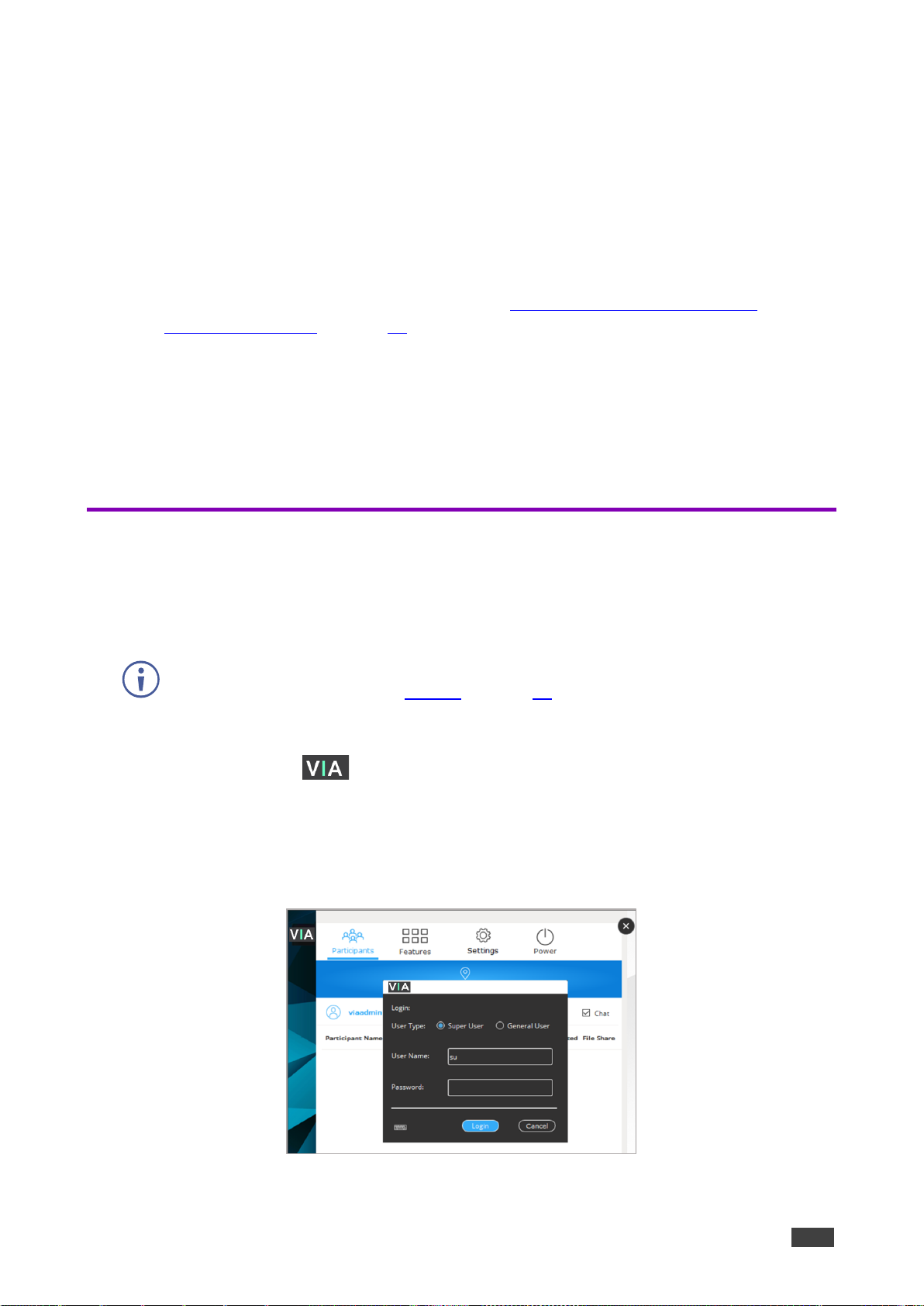
Kramer Electronics Ltd.
VIA Campus² – For Web Administrator: Gateway Dashboard
76
For Web Administrator: Gateway Dashboard
Administrators control an individual VIA Campus² device from two menus:
• Gateway Management Pages – These are a web UI, loaded from inside the device.
The Management Pages are high-level controls which can only be accessed over LAN,
and require an administrator’s password (see For Web Administrator: Gateway
Management Pages on page 16)
• Gateway Dashboard – This web UI, also loaded from inside the device, is only visible
on the Main Display. It controls the meeting interface and is described in this chapter.
Depending on local permission settings, non-administrators can change many of the
Dashboard settings.
A VSM (VIA Site Manager, optional) may also be used to centrally control all VIA devices.
Logging in to the Gateway Dashboard
The Gateway Dashboard is accessed with a mouse and keyboard connected directly to the
VIA gateway unit (it is also possible to use an external device by logging into a meeting and
activating Collaboration mode).
Access to the Gateway Dashboard is controlled by the Quick Client Access setting in the
Via Settings > System tab (see System on page 43).
To log in to the Gateway Dashboard Settings:
1. Click the VIA icon in the lower left of the main display. If there is no VIA icon press
CTRL-Tab and select the Collaboration menu. The Gateway Dashboard menu opens.
2. Click Settings. The login window appears.
3. Type an administrator username and password (default user name = su, default
password = supass).
Figure 82: Gateway Dashboard Settings Login Page
Page 77

Kramer Electronics Ltd.
VIA Campus² – For Web Administrator: Gateway Dashboard
77
Available Options:
• Participants– View the list of participants, chat with a participant or control their screen.
• Features – Enable/disable meeting features, interaction with participants, manage
recordings and display screen.
• Settings – Manage LAN and WiFi, device settings and install third party apps. Requires
an administrator’s password.
• Power – Reboot, reset or turn off the VIA Campus².
Page 78

Kramer Electronics Ltd.
VIA Campus² – For Web Administrator: Gateway Dashboard
78
Settings
LAN Settings
Use the Settings menu to change the IP address, DNS server and default gateway of your
VIA Campus² unit.
• The default IP setting is DHCP that assigns an automatic IP address to your unit. This enables
easy plug and play setup when connecting your VIA Campus² to the network. The following
explains how to change a static IP address.
• When changing these settings, make sure they are correct. Incorrect values can cause a loss
of communication.
• An Administrator Login is required for the Settings menu.
To change the LAN settings:
1. Login to Gateway Dashboard settings (see Logging in to the Gateway Dashboard
on page 76) and select LAN settings.
Figure 83: LAN Setting Tab on Gateway Dashboard
2. Under Connection Type select Static.
3. Enter as required, Host Name, IP Address, Subnet Mask, Default Gateway, DNS Server.
4. Click Apply.
5. Click OK in the Confirmation Message.
The system reboots with the new settings.
Page 79

Kramer Electronics Ltd.
VIA Campus² – For Web Administrator: Gateway Dashboard
79
Enabling a Second Network
VIA Campus² enables you to connect to the device using two separate networks. For details
about how to properly configure this feature, refer to VIA Multiple Network Installation Guide,
available at: www.kramerav.com/product/VIA Campus².
To enable a second network:
• On the Gateway Dashboard Settings Screen, select the Enable Dual Network
checkbox.
To view and/or change LAN settings for the second network, select Show LAN2 Details
from the dropdown.
If you do not require a second network, make sure to disable the dual network feature
and deactivate or unplug the unneeded RJ-45 cable to avoid unwanted communication
from this socket.
Scaling User Dashboard for High Resolution Screen
The Kramer VIA app taskbar menu enables you to enlarge your VIA dashboard when using a
device with a 4K resolution screen.
To scale your dashboard when using a high-resolution screen:
1. In your computer taskbar, click the VIA taskbar icon.
The taskbar menu appears.
2. Click Settings in the taskbar menu.
The Settings screen appears.
3. Select the scaling option.
The dashboard is scaled.
This feature only appears in the taskbar menu when you are using a device with 4K resolution
to connect to the meeting.
Page 80
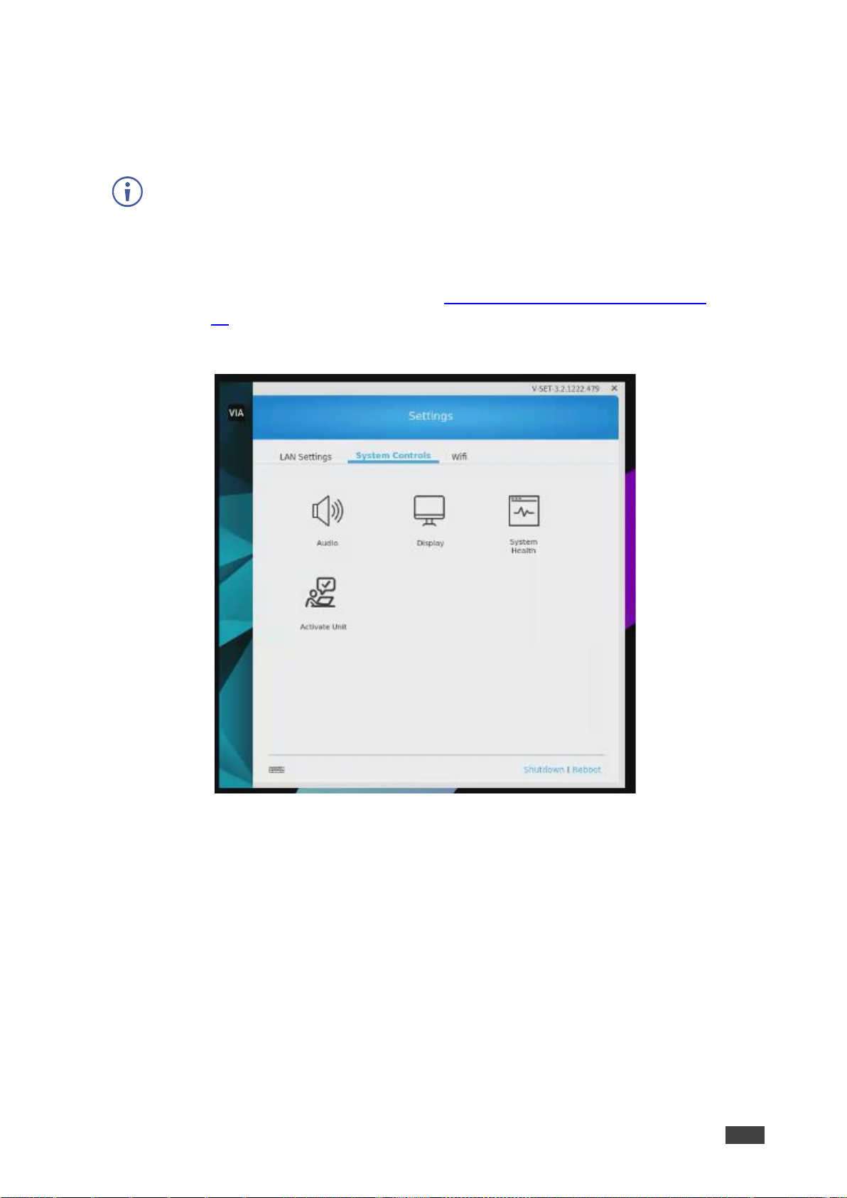
Kramer Electronics Ltd.
VIA Campus² – For Web Administrator: Gateway Dashboard
80
System Controls
Change system controls such as audio settings and monitor display settings and system
health. You can also view log files and activate your VIA Campus² unit.
• The log folder is only available if system logging is activated.
• The VIA Campus² unit is pre-activated by Kramer. If your license has been revoked, you can
activate it here.
To access system controls:
1. On the Gateway Dashboard Settings (see Logging in to the Gateway Dashboard
on page 76), click System Controls.
The System Controls tab appears.
Figure 84: System Control Tab
Available Options:
• Audio – Select audio input and output options.
• Display – View the details of the connected display.
• System Health – Check connection statuses (click the Check Status button).
• Activate Unit – View or enter the VIA Campus² license details.
Page 81

Kramer Electronics Ltd.
VIA Campus² – For Web Administrator: Gateway Dashboard
81
Configuring Dual Displays
VIA Campus² enables you to connect two displays simultaneously. The two displays operate
in the manner of standard Windows extended displays: As a single extended display or as two
identical clones.
Gateway Management settings also control the extended display. For more information see
see Configuring dual displays on page 13.
To configure the behavior of dual displays:
1. Open the Gateway Dashboard on the Main Display:
a. Connect a keyboard and mouse to the USB
input of the VIA Campus².
b. Click the VIA icon in the lower left of
the main display. If there is no VIA icon press
CTRL-Tab and select the Collaboration
menu. The Gateway Dashboard opens.
2. Click System Controls. The login window appears.
a. Enter the administrator username and password (default user name = su, default
password = supass).
3. On the System Controls tab, click Display. The Display menu opens:
a. Page down to Multiple
displays and set how you
want the displays handled:
Extend, duplicate or use just
one of the displays. Use
“Extend” if you want to display
different content on each
screen.
b. If you set it to Extend the
displays: The primary display
is 1 and the secondary display
2.
4. Close the Gateway Dashboard.
Page 82
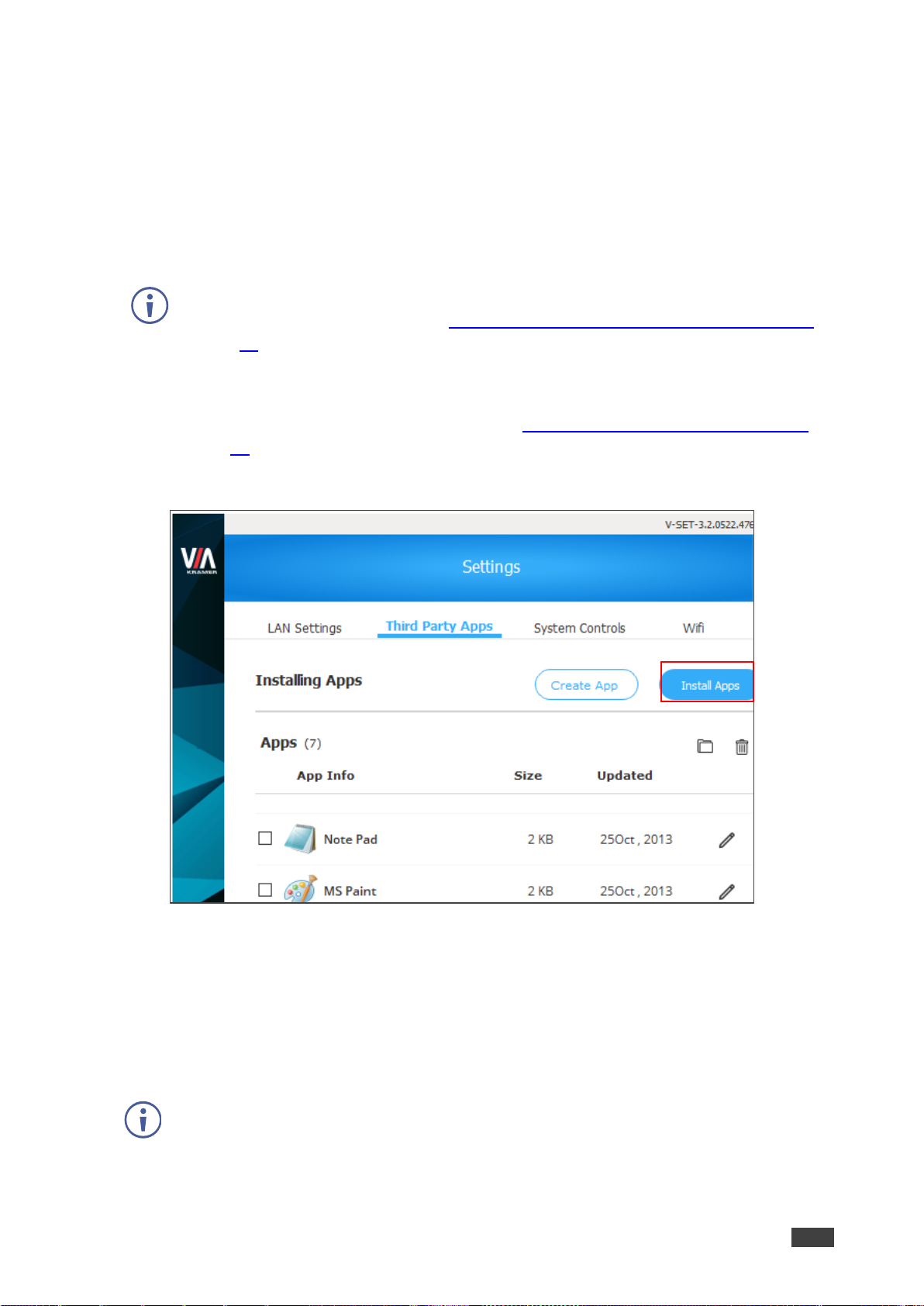
Kramer Electronics Ltd.
VIA Campus² – For Web Administrator: Gateway Dashboard
82
Adding Third Party Apps
The Gateway Dashboard menu can be used to install third party apps on the VIA Campus².
• Shortcuts to installed apps can be displayed on the VIA main display screen.
• Third party apps can be run on the Gateway - No sharing is required (a keyboard or
mouse must be attached to the USB ports on the Gateway).
• They can also be run from a remote device connected to the Gateway.
Administrators can disable the Gateway Dashboard’s Third Party Apps menu in the
Gateway Management Pages, see VIA Campus Features – Configure Client Menus
on page 58).
To add a third-party app to VIA Campus²:
1. Log into the Gateway Dashboard Settings (see Logging in to the Gateway Dashboard
on page 76).
2. Click Third Party Apps, the Third Party Apps window opens.
Figure 85: Third Party App Page
3. Click Install Apps; A message appears.
4. Click Yes; You are logged out of the viauser account.
5. Log in to the viaadmin account (default password = viaadmin); The Windows desktop
appears.
6. Open a browser and download the desired app from the internet.
Remember the location where the app is stored on your Gateway.
7. Log out of the viaadmin account and log in to the viauser account (no password
required); The VIA main display appears.
Page 83

Kramer Electronics Ltd.
VIA Campus² – For Web Administrator: Gateway Dashboard
83
8. Log back into the Gateway Dashboard Settings (see Logging in to the Gateway
Dashboard on page 76).
9. Click Third Party Apps; The Third Party Apps window opens.
10. Click the file icon; A file browser opens.
11. Open the new app file; The New App message appears.
12. Select Yes if you want to show a shortcut on the main display, and click OK.
After the session is reset, a shortcut to the new app is added in the dashboard’s Third
Party Apps page and (if this option was chosen) in the main display’s shortcut tray.
To change the position of the main display shortcut tray, click the settings icon on the tray and
select the desired position.
Figure 86: Main Display Shortcut Tray
Page 84

Kramer Electronics Ltd.
VIA Campus² – For Web Administrator: Gateway Dashboard
84
Monitoring Bandwidth Usage
VIA Campus² enables you to monitor how much bandwidth you are using while
communicating.
To monitor bandwidth usage:
1. In your computer taskbar, click the VIA icon.
The taskbar menu appears.
2. Click Settings in the taskbar menu.
The client preferences screen appears.
3. Under Network Monitor Tool, click the Activate system log and network graph switch.
Additional controls for the Network Monitoring Tool appear.
4. Click Open Network Graph.
The VIA Network Graph window appears. By default, the graph shows live bandwidth
usage.
5. Select a date from the Session drop-down to see the graph from another session.
The graph of the session is played back as a video.
Page 85
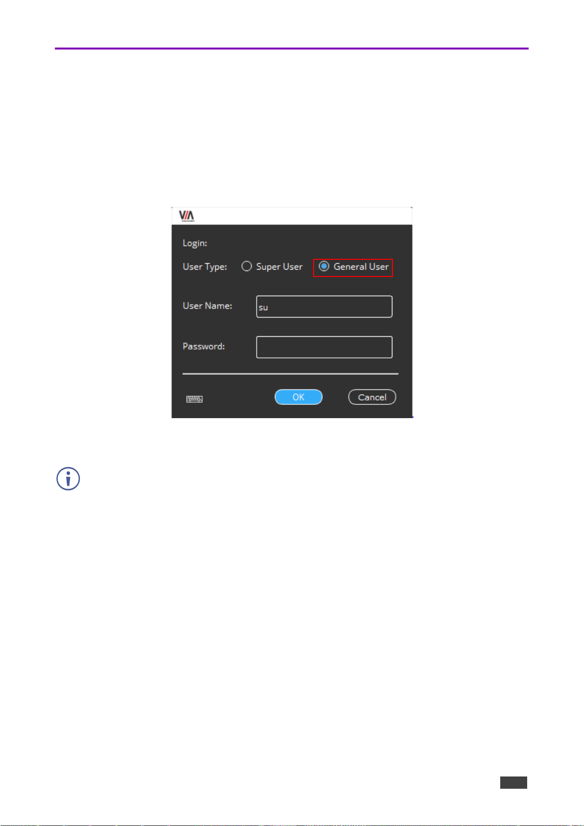
Kramer Electronics Ltd.
VIA Campus² – For Web Administrator: Gateway Dashboard
85
Features - Changing Saved Files Location
VIA Campus² enables you to change the location of the VIA Cloud directory. VIA Cloud is
where all meeting files are saved so that they can be accessed by and shared among
participants in a VIA meeting. The default location for VIA Cloud is the VIA Campus² internal
storage.
To change the saved files’ location:
1. On the Gateway Dashboard, Click Settings; The login window appears.
Figure 87: Settings Login Window
2. Select General User and click OK.
Leave the Password field blank.
Page 86

Kramer Electronics Ltd.
VIA Campus² – For User: Connecting via VIA Campus²
86
For User: Connecting via VIA Campus²
VIA Campus² enables multiple participants to connect for flexible local and remote on-screen
meeting, presenting and collaborating.
You can connect to it from a distance over LAN, locally over WiFi or using an HDMI cable.
Depending on how your system is setup, you can display screens from phones, laptops, Mac
Books or other devices, whether connected locally or remotely.
To connect local or remote sources:
• Use an installed or temporary VIA app (the recommended method). See Installing or
Running the VIA app on page 87.
• Use a VIA Pad (a preconfigured device) connected to your laptop. See Presenting from
a VIA Pad on page 90.
To connect local sources only:
• Connect your device to VIA Campus² using an HDMI cable, see Presenting from an
HDMI Source on page 91.
• Present by Casting (screen mirroring) to VIA Campus², see Presenting by Casting
(Screen Mirroring) on page 91.
On Windows devices, presenters can use the Main (communal) display as an additional
(extension) screen, see Presenting with Extended Desktop on page 93.
Page 87
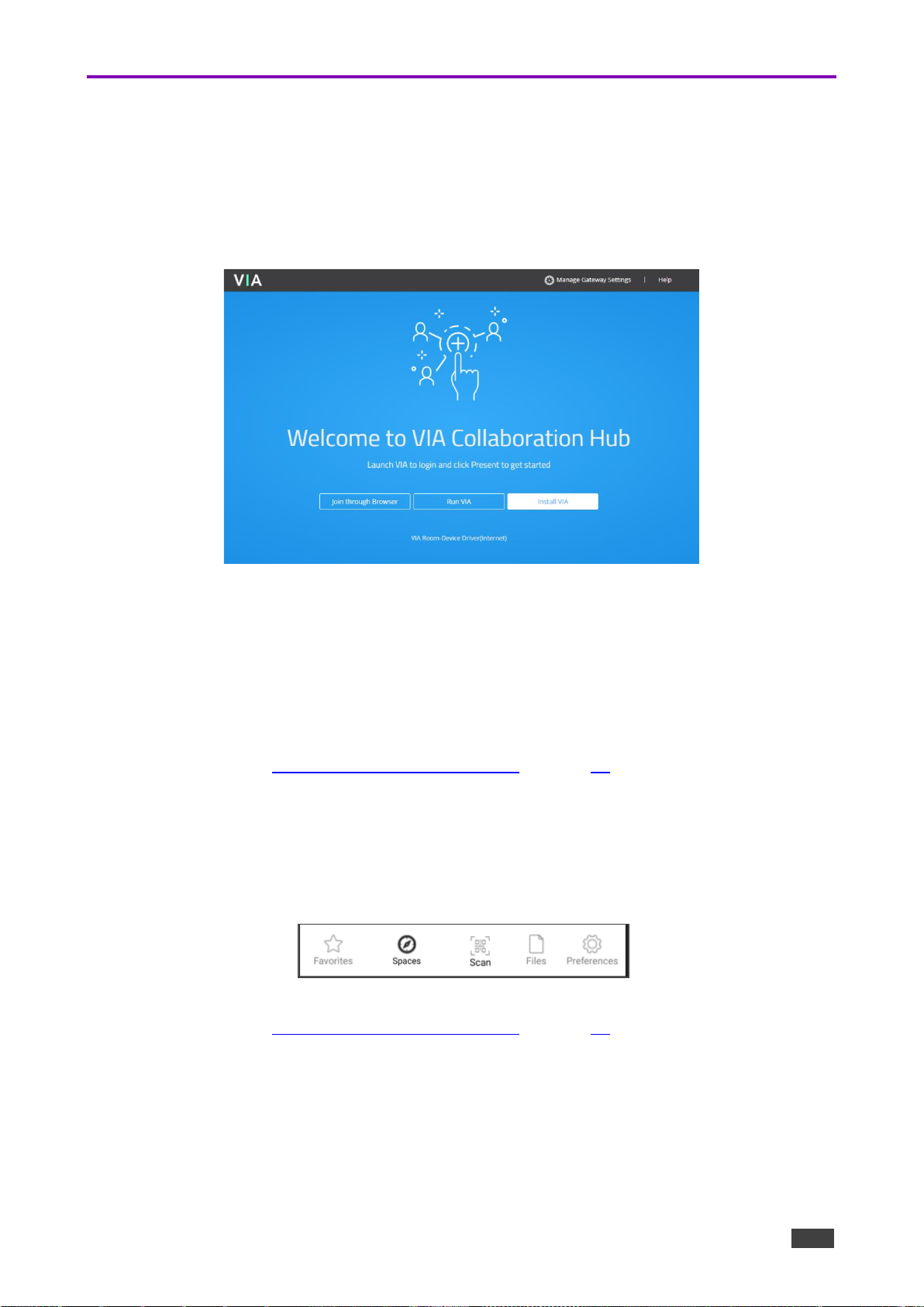
Kramer Electronics Ltd.
VIA Campus² – For User: Connecting via VIA Campus²
87
Installing or Running the VIA app
On a Windows PC
1. Make sure you are connected to the same network as the VIA Campus² device.
2. If you have no VIA app installed, enter the IP address of the VIA Campus² in a browser
window: The VIA device loads the Welcome page onto your display:
Figure 88: The VIA Collaboration page.
3. Select one of the following:
▪ Run VIA - Downloads a temporary Kramer VIA app which you can run without
installing to join the meeting.
▪ Install the VIA app – Install the VIA APP and use it to join meetings and moderate.
▪ Join through Browser – Run the VIA Campus² menu in your browser.
4. Continue with Joining a Room with the VIA app on page 88.
On Android or iOS
1. Download and install the free Kramer VIA app from Apple App Store or Google Play or
scan the QR code (if shown).
Figure 89: Android Toolbar
2. Continue with Joining a Room with the VIA app on page 88.
Page 88
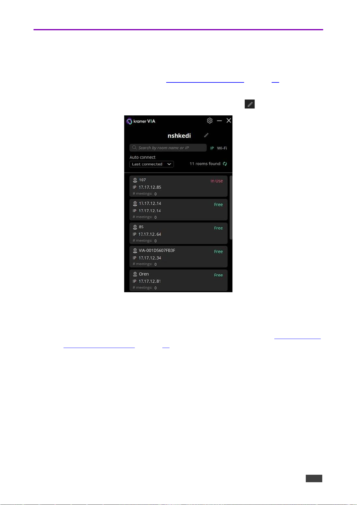
Kramer Electronics Ltd.
VIA Campus² – For User: Connecting via VIA Campus²
88
Joining a Room with the VIA app
1. Make sure you are connected to the same network as the VIA Campus² device.
2. Open your installed VIA app.
▪ If you are using a VIA Pad, see Presenting from a VIA Pad on page 90.
3. In the Kramer VIA application, the Room Selection window appears.
4. To change the name used to identify you, click the pencil icon .
Figure 90: VIA App Window
5. Select a room or enter the IP address of the VIA meeting space you are joining.
6. A pop-up window will request that you enter the Room Code.
7. The VIA User Dashboard appears on your device screen: Continue with Presenting from
the VIA User Dashboard on page 89.
Page 89

Kramer Electronics Ltd.
VIA Campus² – For User: Connecting via VIA Campus²
89
Presenting from the VIA User Dashboard
Invite additional users to the meeting
Leave the room
1. Select what you want to share:
• Screen – Share your screen. Click the
down arrow “Extend” (Windows only) to
add the main display as an extension
screen of your laptop, may install a
screen driver.
• App – Share a window or app that you
are using.
• Media – Share (stream) a media file.
If Media is selected, a list of media is
shown to the right of the Share button.
• HDMI – Enable/disable sharing over an
HDMI connection.
2. Click SHARE:
• The SHARE button becomes the STOP
button.
• Your screen, app or media will be
displayed on the main display.
Figure 91: share
3. Interact with participants:
Click the green arrow to the right of
STOP:
• View the participants.
• Chat and send files to participants.
4. Control what you share:
4 buttons below STOP, green = active.
Pause sharing -–Your screen freezes
on the main display (the VIA app is
minimized).
Present privately—No one else can
present (was “Do Not Disturb”).
Remove other presenters.
Allow remote control – Enable other
users to control your device in
Collaboration mode.
• Volume
control for shared media.
Figure 92: Interacting with Participants
5. Collaborate on the main display:
3 or 4 buttons at the bottom of the User Dashboard
Collaboration – Adds a mouse icon with your name on the main display, blue if collaborating.
White board – Opens drawing/ annotation controls on the main display, lights blue if active.
View display – View a copy of the Main Display on your personal device (not if presenting).
Moderator – Visible if Moderating is permitted, orange when moderating.
See Moderating - Controlling the Meeting on page 100.
Page 90

Kramer Electronics Ltd.
VIA Campus² – For User: Connecting via VIA Campus²
90
Presenting from a VIA Pad
Your VIA Pad needs to have been paired with the VIA Campus² unit before it is used
(see Configuring VIA Pad Settings on page 25).
The following instructions are for Windows and Mac OS users.
To join a meeting using a VIA Pad:
1. Connect your VIA Pad to a USB connector on your laptop.
2. Open the VIA Pad folder and double-click the VIA Pad app.
The Kramer VIA login window appears.
3. If necessary, type in your room code.
4. Click Join.
Your VIA Pad lights blue when ready.
The VIA User Dashboard and taskbar appear on your device screen.
5. Use VIA Pad to present:
• Press once – Starts presenting or stops presenting your screen on the main display.
When you are presenting, the VIA Pad LED banner lights green. When you stop
presenting, the LED banner lights blue.
• Press twice while presenting – Freezes or unfreezes your screen. When your screen
is frozen, the VIA Pad LED banner flashes green.
• Long press – Displays your screen in full screen mode on the main display,
displacing any other participant screen.
Page 91

Kramer Electronics Ltd.
VIA Campus² – For User: Connecting via VIA Campus²
91
Other Presentation Methods
• Presenting from an HDMI Source on page 91.
• Presenting by Casting (Screen Mirroring) on page 91.
• Presenting with Extended Desktop on page 93.
• Sharing Media from the User Dashboard on page 94.
• Using the Media button on page 94.
• RTSP Streaming Through VLC on page 95.
• RTP Streaming Through VLC on page 99.
Presenting from an HDMI Source
VIA Campus² enables you to show content on the main display from an external device
connected to the HDMI IN connector. When a device is connected to the HDMI input, it
overrides other VIA Campus² sources.
To show content from an HDMI source:
• Connect the external device to the VIA Campus² HDMI IN Connector ( in Defining
VIA Campus² on page 9: The external content appears on the main display.
On the VIA User Dashboard, click the HDMI Input icon to toggle between the HDMI
input and the VIA meeting input on the main display.
Presenting by Casting (Screen Mirroring)
You can use VIA Campus² as a screen mirroring device, without the need to login to a
meeting or download any software.
The procedure by which you connect in this way depends on the device you are using:
• Apple laptops and iPhones use X Airplay Service - Presenting with iOS/OS X Airplay
Service on page 91.
• Windows laptops and Android phones use Miracast - Mirroring Using Miracast
on page 92.
Presenting with iOS/OS X Airplay Service
All participants in a meeting using an Apple device can mirror their screen on the main display
using the Apple AirPlay service. No application is required to activate this mode. However, an
administrator must enable the iOS mirroring feature in the VIA Campus² Gateway
Management pages (see Presentation on page 44).
Minimum requirements for mirroring using Airplay services are:
• iPhone or iPad/Mini iPad – Minimum version iOS 10 (iOS 12 or higher is recommended).
• Mac Books and Apple Computers – Minimum version OS X 10.11 (Mojave or higher is
recommended).
Page 92

Kramer Electronics Ltd.
VIA Campus² – For User: Connecting via VIA Campus²
92
AirPlay discovery relies on Bonjour (mDNS). For more information see VIA IT Deployment
Guide, available for download at: www.kramerav.com/product/VIA Campus².
To mirror your screen using AirPlay Services:
1. Connect your Apple device to the network that VIA Campus² is connected to.
2. For iPhone or iPad/Mini iPad: Swipe from the upper right corner to reveal the Control
Center and click Screen Mirroring.
For Mac Books and Apple Computers: Click the AirPlay icon on the Apple Menu Bar,
located in the top right corner of the screen, near the clock.
The Screen Mirroring list appears.
3. Select VIA Campus² AirPlay device name (default = VIA_AirMirror_XXXX, where XXXX
is a random combination of letters and numbers).
If the room code is enabled, a message appears asking you to enter the code.
4. Type the code that appears on the VIA Campus² main display (if activated); Mirroring
starts, and your screen appears on the main display.
To disconnect iPhone or iPad/Mini iPad and stop mirroring:
1. Swipe from the upper right corner to reveal the Control Center.
2. Click Stop Mirroring: Mirroring stops.
Mirroring Using Miracast
VIA Campus² enables you to use the native Miracast feature on your Windows 10 laptop or
Android device to mirror your screen on the main display.
This feature must be enabled by the Web Administrator (see Presentation on page 44).
To mirror using VIA Campus² you need a Windows laptop or an Android device that
supports Miracast.
If the drivers of your Windows laptop are up to date and the “Connect to a wireless
display” option is not available, your device does not support Miracast.
Android operating system versions 4.2 and higher include built-in Miracast technology.
However, some Android 4.2 and 4.3 devices do not support Miracast.
Mirroring Windows Laptops Using Miracast
To mirror a Windows laptop using Miracast:
1. On your Windows laptop, press Windows + K.
The Room Name of your VIA collaboration device appears in the Connect list.
2. Click the Room Name of your VIA device. A PIN code field appears (if Code was
activated on your VIA device).
Select the Allow input from a keyboard… checkbox to enable another participant to
control your laptop from the main display.
Page 93

Kramer Electronics Ltd.
VIA Campus² – For User: Connecting via VIA Campus²
93
3. Enter the Code that appears on the main display and click Connect.
The name of your device appears on the main display and then your screen is mirrored
on the main display.
Mirroring Android Devices Using Miracast
To mirror an Android device using Miracast:
1. In your Android device settings, open WiFi Direct, Miracast, or ScreenCast.
Device options appear on your screen.
2. Click the Room Name of your VIA collaboration device.
A PIN code field appears (if Code was activated on your VIA device).
3. Enter the Code that appears on the main display and click Accept/Connect.
The name of your device appears on the main display and then your screen is mirrored
on the main display.
Presenting with Extended Desktop
VIA Campus² can be setup to add the main display as an extension of the user’s device
desktop. The user’s primary screen is not shared, allowing the user to keep their laptop
display private while sharing.
This feature is available on Windows client laptops only, after installation of the required
drivers. When using this feature for the first time, the system asks you to install the drivers.
Please accept and follow the on-screen instructions. Once the drivers are installed, reboot
your PC to enable the feature.
Mac users can use AirPlay to simulate the same behavior.
To mirror with the Extended Desktop feature:
• On the Kramer VIA User Dashboard, click the Screen-1 icon and select Extended.
Figure 93: Media Player Window
An extension of your device desktop appears on the VIA main display.
• Drag content to the left and beyond your primary screen to show it on the main display.
You can change the relative positioning of the two displays in your device
Control Panel under Screen Resolution.
Page 94
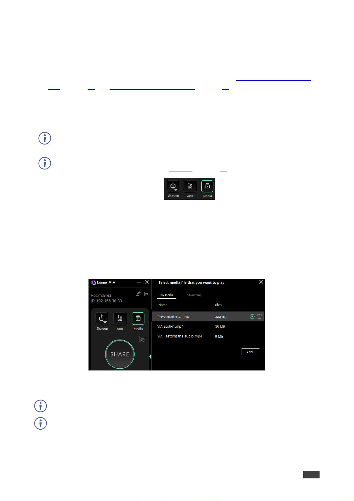
Kramer Electronics Ltd.
VIA Campus² – For User: Connecting via VIA Campus²
94
Sharing Media from the User Dashboard
Use the Media sharing option on the VIA app to stream video to the main display without
sharing your screen. You can also simply share your screen while playing a video.
VIA Campus² also supports direct sharing from VLC player: See RTSP Streaming Through
VLC on page 95 and RTP Streaming Through VLC on page 99.
Using the Media button
Video can be streamed to the main display at a full HD 1080p/60fps rate.
VIA Campus² features a 10Mbps maximum video bitrate for 30fps or 60fps videos and handles
video files of up to 8GB.
The default encoding format is H.264. If your device operating system does not support H.264
encoding, enable JPEG encoding (see Settings on page 78) .
To stream Media:
1. On the User Dashboard, click Media.
2. The media selection window opens on the right, with 2 tabs:
• My Media tab - Lists videos on your hard drive that you added.
• Streaming tab - Lists URLs of (online) videos that you added.
3. Click Add+ (bottom right corner) to add more videos.
4. Listed items are available for streaming in future meetings, including in other rooms, not
just in the present meeting - Once saved, the stream is listed until you delete it.
Figure 94: Media Player Window
5. To play an item, select it and click Share / double click it / click the play button.
Videos are not stored on the VIA Campus²: It handles video playback with the VIA app.
Video files shared from your device to the main display by a native media player such as
QuickTime and/or Windows Media Player may experience lower frame rates, inconsistent
playback, and increased latency, depending on your laptop system’s performance.
Page 95

Kramer Electronics Ltd.
VIA Campus² – For User: Connecting via VIA Campus²
95
RTSP Streaming Through VLC
The Real Time Streaming Protocol (RTSP) is a network control protocol designed for use in
entertainment and communications systems to control streaming media servers. The protocol
establishes and controls media sessions between end points. Clients of media servers issue
commands like play and pause, to facilitate real-time control of playback of media files from
the server.
VIA Campus² supports RTSP. Media played locally on a computer can be streamed,
provided the computer and VIA Campus² are on connected networks.
To Configure RTSP Streaming using VLC Media Player:
1. Open VLC Media Player on your device.
Figure 95: VLC Media Tab
2. Click Media > Stream.
The Open Media window appears.
Page 96
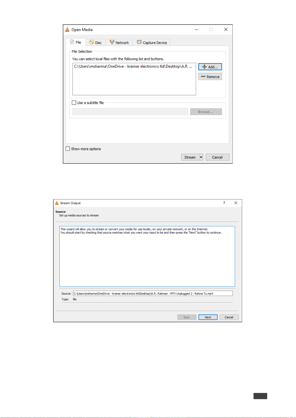
Kramer Electronics Ltd.
VIA Campus² – For User: Connecting via VIA Campus²
96
Figure 96: Media Window
3. Click Add and select a file to stream and click Stream.
The Stream Output/Source window appears.
Figure 97: Stream Output Window
Page 97
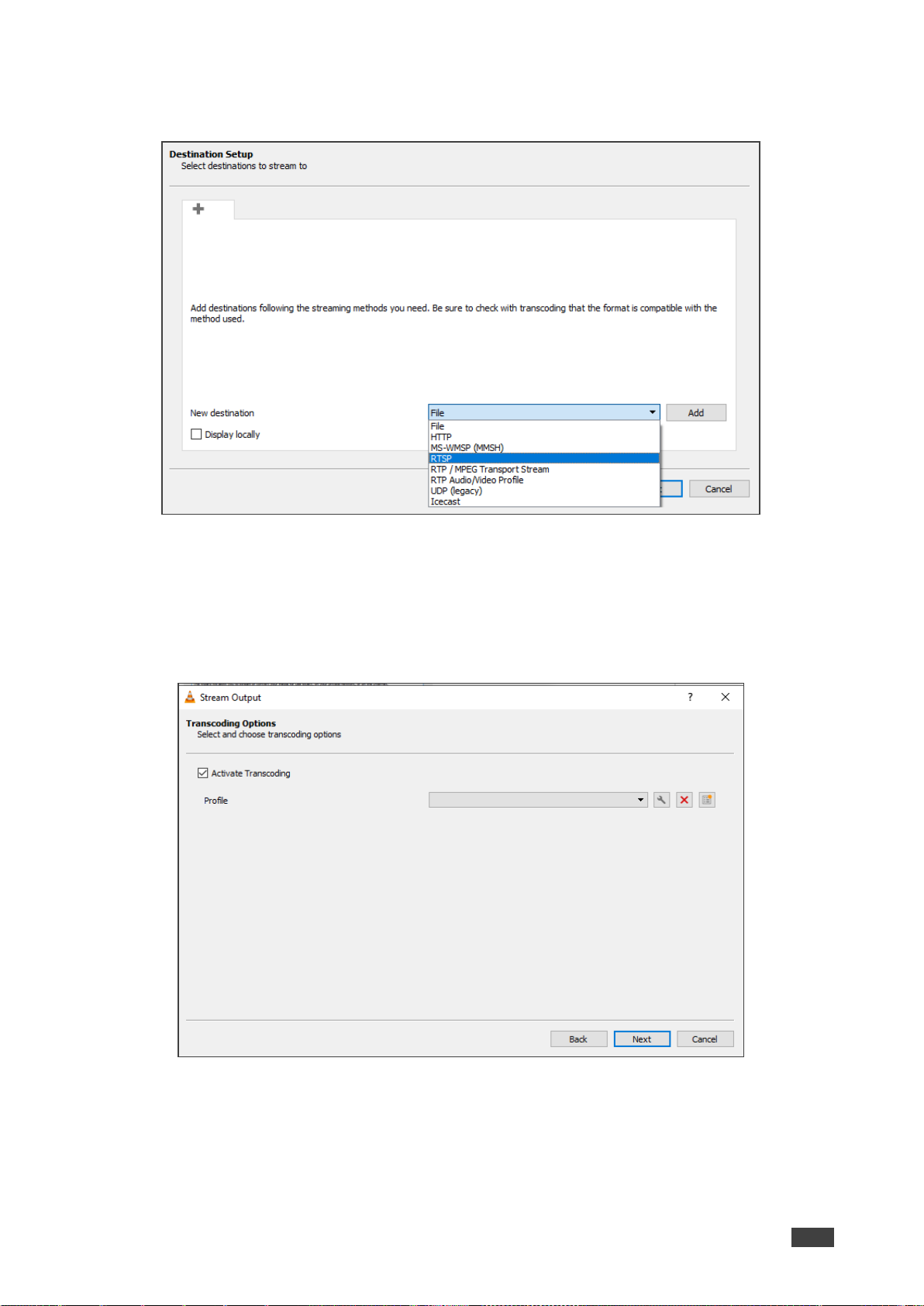
Kramer Electronics Ltd.
VIA Campus² – For User: Connecting via VIA Campus²
97
4. Click Next.
The Stream Output/Destination Setup window appears.
Figure 98: Destination Setup Window
5. Select RTSP from the New Destination drop down and click Add.
The RTSP tab appears.
6. Type a short name to be used as a Path and click Next.
The Stream Output/Transcoding Options window appears.
Figure 99: Transcoding Options Window
Page 98

Kramer Electronics Ltd.
VIA Campus² – For User: Connecting via VIA Campus²
98
7. Clear the Activate Transcoding checkbox and click Next.
The Stream Output/Option Setup window appears.
Figure 100: Options Setup Window
8. Select Stream all elementary streams and click Stream.
9. On the VIA User Dashboard, Select Multimedia.
10. The Multimedia player window appears with the My Media tab open.
11. Click Streaming.
12. The Streaming tab appears.
13. Click +.
The URL Name window appears.
14. In the URL Name field, enter a name for the video stream.
15. In the URL path field, enter a URL name in the following format:
rtsp://<local computer IP address>:8554/<name mentioned in step 6>.
16. Click OK.
17. The name and URL of the streaming media appears in the Media list.
18. Select the RTSP stream in the Streaming table and click the play button.
RTSP Streaming using VLC Media Player is configured and the media appears on the
main display.
Page 99

Kramer Electronics Ltd.
VIA Campus² – For User: Connecting via VIA Campus²
99
RTP Streaming Through VLC
The Real-time Transport Protocol (RTP) is a network protocol for delivering audio and video
over IP networks. RTP is used extensively in communication and entertainment systems that
involve streaming media, such as telephony, video teleconference applications, television
services and Web-based push-to-talk features.
VIA Campus² supports RTP. Media can stream on a VIA Campus² unit, provided the computer
and VIA Campus² are on connected networks.
To stream RTP using VLC:
1. Open VLC.
2. Click Media > Stream.
3. Click Add and select a file to stream and click Stream.
4. Click Next on the next screen.
5. Choose RTP/MPEG Transport Stream from the New Destination drop down and click
Add.
6. Enter VIA Campus² unit’s IP address and click Next.
The Stream Output/Transcoding Options window appears.
7. Clear the Activate Transcoding checkbox and click Next.
The Stream Output/Option Setup window appears.
8. Select Stream all elementary streams and click Stream
9. On the VIA User Dashboard, select Media.
10. Click Add+ and add the URL of the video stream.
11. Select your RTP stream and click the play button.
RTP Streaming using VLC is configured and the streaming video appears on the main
display.
Page 100

Kramer Electronics Ltd.
VIA Campus² – For User: Connecting via VIA Campus²
100
Moderating - Controlling the Meeting
VIA Campus² enables any authorized meeting participant to become a moderator. A meeting
moderator has control over certain VIA functions that affect other participants, such as:
Moderator Mode must be enabled/disabled by an Administrator in the Gateway Management Pages
Device Management > VIA Settings > Moderator Mode. See Moderator Mode on page 50.
The moderator must access VIA Campus² with a VIA app.
The following Moderator options can be enabled/disabled by the administrator:
• Only certain users can moderate or a password is required to moderate.
• Moderators can enable or disable the chat feature.
• Moderators must confirm the start of a presentation.
• Sessions cannot start until the Moderator is present.
If you can become the moderator, the Moderator icon is shown on your User
Dashboard:
1. Click the Moderator icon on your User Dashboard to become the moderator.
• If sessions cannot start without a moderator, the session will start when you click the
Moderator icon and end when you click it a second time.
2. The moderator icon turns orange.
Figure 101: Enabling Moderator mode
3. To stop being moderator, re-click the Moderator icon.
4. If the moderator can disable Chat, a checkbox is visible at the top right of the Chat tab.
Figure 102: Disabling chat in Moderator mode
Enabling
Moderator
 Loading...