

Page 1

AFM-20DSP-AEC Quick Start
P/N:
2900- 301486QS
Rev:
1
Scan for full manual
AFM-20DSP-AEC Quick Start Guide
This guide helps you install and use your AFM-20DSP-AEC for the first time.
Go to www.kramerav.com/downloads/AFM-20DSP-AEC to download the latest user manual and check if
firmware upgrades are available.
Step 1: Check what’s in the box
AFM-20DSP-AEC 20 Port Audio Matrix
1 Set of rack ears
1 Quick Start guide
1 Power cord
4 Rubber feet
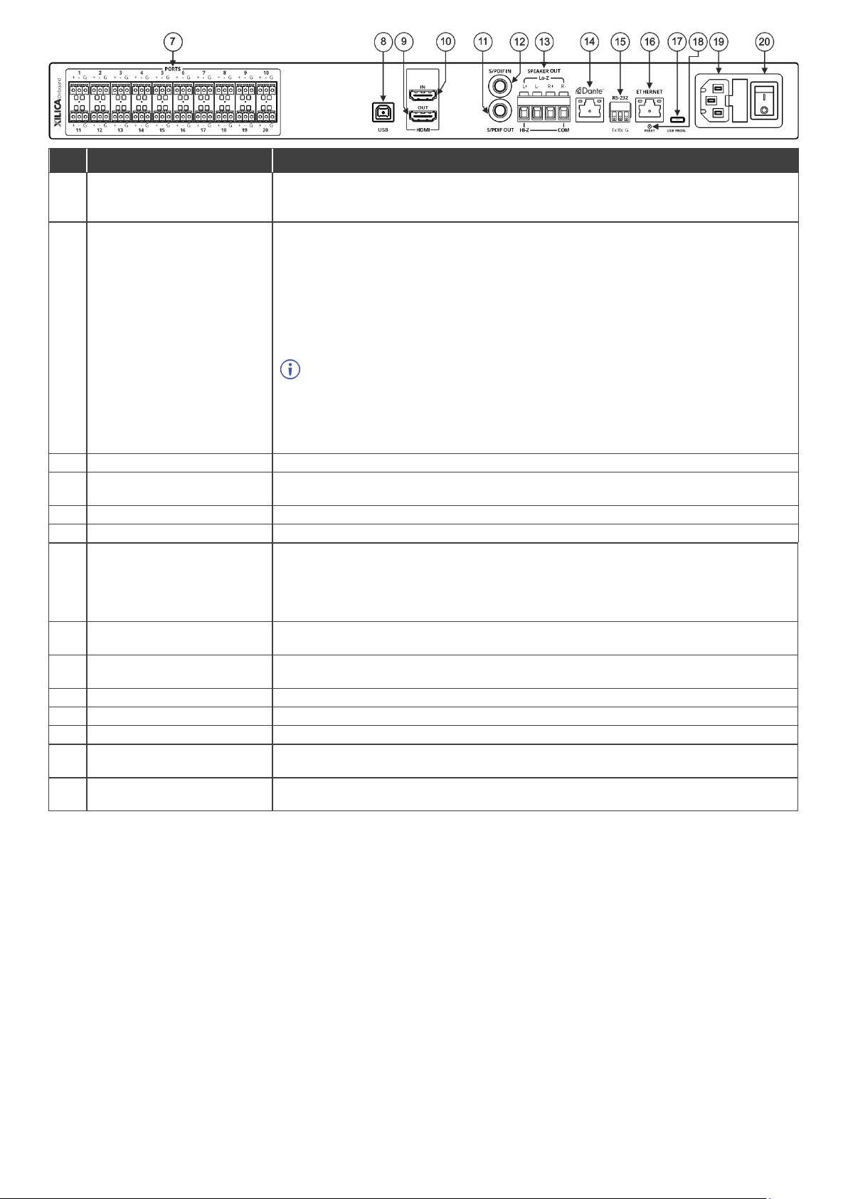
Step 2: Get to know your AFM-20DSP-AEC
#
Feature
Function
1
STATUS LED
Indicates the system’s status:
• 3 cycles of red/blue/off/green LEDs
that flash in sequence for 30 seconds
when the system starts up, and the
application has not been launched.
• Flashes green when the application starts.
• Stays green when system is ready for use.
2
PORTS LEDs (1 to 20)
Indicate the port’s status:
• Green when an input signal is
detected, and the port is defined as
line in.
• White when defined as line out.
• Blue when defined as mic in.
• Red when in clipping state.
• Yellow when in limiting state.
• Off when there is no signal on the input.
3
IN OUT Dante™ LEDs
(1 to 4)
Indicate the Dante’s signal status:
• Green when a signal is detected.
• Red when clipping occurs.
• Yellow when in limiting state.
• Off when no signal is detected.
4
HDMI™ LEDs
EMBED
Turns green when an analog audio signal is associated with the HDMI OUT signal.
Otherwise, it stays OFF.
DE-EMBED
Turns green when the HDMI IN audio signal is detected. Otherwise, it stays OFF.
5
IN OUT USB or S/PDIF LEDs
Indicate the USB or S/PDIF’s status:
• Green when a signal is detected.
• Off when no signal is detected.
If a signal is detected on one channel, either left only or right only, the status LED is
green.
6
CH 1(L)/CH 2(R) AMPLIFIER
LEDs
Indicate the amplifier’s signal status:
• Green when a signal is detected.
• Off when no signal is detected.
On the web page, CH1 and CH2 are referred to as AMP 1 and AMP 2, respectively.
Page 2
#
Feature
Function
7
PORTS 3-pin Terminal Block
Connectors (1 to 20)
Interchangeable balanced mono-audio ports. Connect to an audio source or acceptor in 1
of 8 selectable I/O configurations: 16x4, 14x6, 12x8, 12x8 AEC ,10x10, 8x12, 6x14, 4x16.
Define each port as line in, mic in, mic + 48V in, or line out.
8
USB
AFM-20DSP-AEC can process the USB audio as a stereo speaker or operate as an audio
line-in or microphone for an audio recorder application or call conferencing.
When the AFM-20DSP-AEC is connected to a computer via USB-B:
• In the computer’s Settings > Manage sound devices > Output devices, the AFM-
20DSP-AEC USB shows as “Speaker USB AUDIO CODEC”.
• In a computer recoding application, the audio input settings for AFM-20DSP-AEC
show as “Line USB AUDIO CODEC”.
Important:
• The computer’s “Output” device (such as speakers) shows in the AFM-20DSP-AEC
embedded web pages as a USB Digital “Input”.
• The computer’s “Input” device (such as a microphone) shows in the AFM-20DSP-
AEC embedded web pages as a USB Digital “Output”.
9
HDMI™ OUT Connector
Connect to an HDMI acceptor to embed an audio signal from the matrix.
10
HDMI™ IN Connector
Connect to an HDMI source to de-embed the audio signal (the video signal is passed
through to the output).
11
S/PDIF OUT RCA Connector
Connect to a digital stereo audio acceptor.
12
S/PDIF IN RCA Connector
Connect to a digital stereo audio source.
13
SPEAKER OUT
Outputs two selected audio signals in two channels.
• For Lo-Z: connect stereo output to Lo-Z speakers: L+ and L- to the left speaker;
R+R- to the right speaker.
• For Hi-Z (70V or 100V): connect Hi-Z and COM to mono Hi-Z speakers.
14
Dante PoE RJ-45 Port
Connect to Dante audio through the network. Provides 4 Tx channels and 4 Rx channels.
By default, DHCP is enabled.
15
RS-232 3-pin Terminal Block
Connector
Connect to a PC/serial controller to control the device.
16
ETHERNET RJ-45 Connector
Connect to a PC via a LAN to control the device and for firmware upgrades.
17
Micro USB PROG. PORT
Connect to your PC to control the device.
18
RESET Recessed Button
Press and hold for 5 seconds, to reset the configuration to its default parameters.
19
Mains Power Connector and
Fuse
Plug in for the power cord.
20
POWER Illuminated Power
Switch
Turns the device on and off.
Page 3

Step 3: Mount AFM-20DSP-AEC
To rack mount the machine, attach both rack ears
(remove the screws from each side of the machine
and replace screws through the rack ears) or place
the machine on a table.
• Ensure that the environment (e.g., maximum ambient temperature &
air flow) is compatible for the device.
• Avoid uneven mechanical loading.
• Appropriate consideration of equipment nameplate ratings should be
used for avoiding overloading of the circuits.
• Reliable earthing of rack-mounted equipment should be maintained.
Step 4: Connect inputs and outputs
Always turn off the power on each device before it is connected to the AFM-20DSP-AEC device.
For optimum range and performance, use the recommended Kramer cables available at
www.kramerav.com/product/AFM-20DSP-AEC. The use of third-party cables may cause damage!
Page 4

Step 5: Connect the power
Connect the power cord to AFM-20DSP-AEC and plug it into the mains electricity.
Safety Instructions (See www.kramerav.com for updated safety information)
Caution:
• There are no operator serviceable parts inside the unit.
Warning:
• Use only the power cord that is supplied with the unit.
• Disconnect the power and unplug the unit from the wall before installing.
• Do not open the unit. High voltages can cause electrical shock! Servicing by qualified personnel only.
• To ensure continuous risk protection, replace fuses only according to the rating specified on the product label which located on the bottom of the unit.
Step 6: Operate AFM-20DSP-AEC
To operate AFM-20DSP-AEC, use:
• Embedded web pages via the
Ethernet.
• RS-232 serial commands
transmitted by a touch screen
system, PC, or other serial
controller.
RS-232 Control / Protocol 3000
Baud Rate:
115,200
Parity:
None
Data Bits:
8
Command Format:
ASCII
Stop Bits:
1
Example: (adjust the amplified audio from analog audio 1 to -10dB):
#x-aud-lvl out.amplified_audio.1.audio.1,-10
Default Ethernet Parameters
IP Address:
192.168.1.39
UDP Port #:
50000
Subnet mask:
255.255.0.0
TCP Port #:
5000
Gateway:
192.168.0.1
Username/Password
Admin/Admin
Factory Reset
Recessed Button
Press and hold for 5 seconds to reset the configuration to its
default parameters.
Protocol 3000:
“#factory” command.
Web Pages:
In the Settings page, click Factory Reset.
 Loading...