

Page 1

Operator's Manual
//
Wheel loaders
Models 351-01 / 351-02 / 351-03
From serial nos. 351 01 0001 / 351 02 0001 / 351 03 0001
Edition 1.0
Order number 1000245584
Language EN
Page 2

Documentation Language Order no.
Operator's Manual EN 1000245584
DE 1000159213
Service Booklet
Spare parts catalogue, model 351-01
Spare parts catalogue, model 351-02 1000249074
Spare parts catalogue, model 351-03 1000249075
Legend
Original Operator's Manual –
Translation of original Operator's
Manual
Edition
Date
EN 1000159214
FR 1000159215
1000249073
DE/EN/FR
x
1.0
02/2010
Document
Copyright – 2010 Kramer-Werke GmbH
Printed in Germany
All rights reserved, in particular the copyright, the right of reproduction and the right of distribution applicable worldwide.
No part of this publication may be reproduced, translated or used in any form or by any means – graphic, electronic or mechanical includ-
ing photocopying, recording, taping or information storage or retrieval systems – without prior permission in writing from the manufacturer.
No reproduction or translation of this publication, in whole or part, without the written consent of KRAMER-WERKE GmbH.
Any infringement of legal provisions, in particular of those regarding copyright protection, shall be subject to civil and criminal law prose-
cution.
KRAMER-WERKE GmbH keep abreast of the latest technical developments and constantly improve their products. For this reason, we
may from time to time need to make changes to diagrams and descriptions in this documentation which do not reflect products which
have already been delivered and which will not be implemented on these machines.
Technical data, dimensions and weights are given as an indication only. Responsibility for errors or omissions not accepted.
The cover features the machine with possible optional equipment.
Kramer-Werke GmbH
Wacker-Neuson-Str. 1
D-88630 Pfullendorf
Tel. 0080090209020
E-mail info@kramer.de
www.kramer.de
BA 35101/02/03 EN
Page 3

Table of contents
Table of contents
Table of contents
Declaration of conformity EG
EC declaration of conformity (model 351-01) .........................................................EG-1
EC declaration of conformity (model 351-02) .........................................................EG-2
EC declaration of conformity (model 351-03) .........................................................EG-3
Introduction 1
General information on the Operator's Manual ........................................................ 1-1
Abbreviations/symbols ....................................................................................... 1-1
General information on machine safety ................................................................... 1-1
Machine outside view .............................................................................................. 1-2
Models and trade names: overview ......................................................................... 1-3
Brief description of the wheel loader ........................................................................ 1-3
General information on the machine ................................................................. 1-3
Main components of wheel loader ..................................................................... 1-3
Hydrostatic drive ................................................................................................ 1-4
Work hydraulics and 4 wheel steering ............................................................... 1-4
Cooling system .................................................................................................. 1-4
Wheel loader warranty ............................................................................................. 1-4
Fields of application and using a wheel loader with an attachment ......................... 1-5
Attachments with authorised material densities ................................................ 1-5
Legal regulations regarding wheel loader operation ................................................ 1-8
General safety instructions ................................................................................ 1-8
Driving licence ................................................................................................... 1-8
Licence/identification ......................................................................................... 1-8
Machine inspections .......................................................................................... 1-9
Documents ........................................................................................................ 1-9
On-board equipment .......................................................................................... 1-9
Machine warning identification (option) ............................................................. 1-9
Type labels and component numbers .................................................................... 1-10
Serial number .................................................................................................. 1-10
Cab number ..................................................................................................... 1-10
Engine number ................................................................................................ 1-10
Variable displacement pump number .............................................................. 1-11
Variable displacement motor number .............................................................. 1-11
Rear axle number ............................................................................................ 1-11
Front axle number ........................................................................................... 1-11
Description of labels and symbols ......................................................................... 1-12
Labels on the outside of the machine .............................................................. 1-12
Labels inside the cab ....................................................................................... 1-14
Labels in the engine compartment .................................................................. 1-17
Safety instructions 2
Identification of warnings and dangers .................................................................... 2-1
Designated use and exemption from liability ........................................................... 2-2
General conduct and safety instructions .................................................................. 2-3
Organisational measures ................................................................................... 2-3
Selection and qualification of staff, basic responsibilities .................................. 2-5
Safety instructions regarding operation ................................................................... 2-6
Normal operation ............................................................................................... 2-6
Applications with lifting gear .............................................................................. 2-8
Trailers and attachments ................................................................................... 2-9
Transporting, towing, loading ............................................................................ 2-9
Safety instructions for maintenance ....................................................................... 2-10
Maintenance work on protective ROPS and FOPS structures .............................. 2-12
Cab, roll-over bar, protective screen ............................................................... 2-12
BA 35101/02/ 03 EN - Ausgab e 1.0 * BA_35101_02_03_10_enIVZ.fm I-1
Page 4

Table of contents
Warning of special hazards .................................................................................... 2-12
Electric energy ................................................................................................. 2-12
Gas, dust, steam, smoke ................................................................................. 2-12
Hydraulics ........................................................................................................ 2-13
Noise ................................................................................................................ 2-13
Oil, grease and other chemical substances ..................................................... 2-13
Battery ............................................................................................................. 2-13
Tyres ................................................................................................................ 2-13
Operation 3
Description of control elements ................................................................................ 3-1
Cab overview ........................................................................................................... 3-2
Instrument panel, multifunctional lever and drive lever (overview) .......................... 3-4
Functional description: telltales ................................................................................ 3-6
Telltale check ..................................................................................................... 3-6
Telltales and warning lights on the indicating instrument .................................. 3-6
Telltales and indicators on the instrument panel ............................................... 3-7
Putting the wheel loader into service ....................................................................... 3-9
Safety instructions regarding commissioning .................................................... 3-9
Important information for the operating staff ...................................................... 3-9
Running-in period of wheel loader ..................................................................... 3-9
Checklist ................................................................................................................ 3-10
Starting checklist .............................................................................................. 3-10
Operation checklist .......................................................................................... 3-11
Parking checklist .............................................................................................. 3-11
Cab ........................................................................................................................ 3-12
Safety instructions regarding cab entrance and exit ........................................ 3-12
Locking/unlocking the door .............................................................................. 3-12
Securing an open door in the arrester ............................................................. 3-13
Opening the right-hand side door to a gap ...................................................... 3-13
Engine cover lock ................................................................................................... 3-14
Opening/closing the engine cover ................................................................... 3-14
Protective screens for front window and/or main lights (option) ............................ 3-14
Removing the protective screens for driving on public roads .......................... 3-14
Fire extinguisher (option) ....................................................................................... 3-14
Fire extinguisher operation .............................................................................. 3-14
Putting the diesel engine into operation ................................................................. 3-15
Preparing to start the engine ........................................................................... 3-15
Starting the engine ........................................................................................... 3-16
Avoiding running the engine under low-load conditions .................................. 3-17
Stopping the engine ......................................................................................... 3-17
Battery master switch (option) ............................................................................... 3-18
Battery master switch operation ...................................................................... 3-18
Key-based drive interlock (option) ......................................................................... 3-18
Key-based drive interlock: scope of delivery ................................................... 3-18
Coding (“training”) new ignition keys ............................................................... 3-18
Enabling (locking) the drive interlock ............................................................... 3-19
Disabling (releasing) the drive interlock ........................................................... 3-19
Deleting coded keys ........................................................................................ 3-19
Safety functions ............................................................................................... 3-19
I-2 BA 35101/ 02/03 EN - Aus gabe 1.0 * BA_35 101_02_0 3_10_enI VZ.fm
Page 5

Table of contents
Drive interlock with code input (option) .................................................................. 3-20
Keyboard for entering codes: overview ........................................................... 3-20
Entering/changing the personal code .............................................................. 3-21
Enabling the drive interlock ............................................................................. 3-21
Disabling the drive interlock ............................................................................. 3-22
Putting the drive interlock out of operation ...................................................... 3-22
Putting the drive interlock back into operation again ....................................... 3-23
Interruption of drive interlock power ................................................................ 3-23
Drive interlock maintenance ............................................................................ 3-23
Oil and fuel preheater (option) ............................................................................... 3-24
General information on the oil and fuel preheater ........................................... 3-24
Oil preheater operation .................................................................................... 3-24
Fuel preheater ................................................................................................. 3-24
Jump-starting the engine (external battery) ........................................................... 3-25
Safety instructions regarding external starting aids ......................................... 3-25
Providing external starting aid ......................................................................... 3-25
Before moving off ................................................................................................... 3-26
Special instructions for driving on public roads ............................................... 3-26
Preparing for driving on public roads ............................................................... 3-26
Bucket transport position ................................................................................. 3-27
Transport position of pallet forks ..................................................................... 3-28
Locking the control lever (joystick) and the 3rd control circuit (attachments) .. 3-29
Functional check of all control elements .......................................................... 3-29
Steering system ..................................................................................................... 3-30
Steering column height and angle adjustment (option) ................................... 3-30
Checking the steering system ......................................................................... 3-30
Wheel synchronisation (front/rear axles) ............................................................... 3-31
Synchronisation when starting the machine .................................................... 3-31
Synchronisation during work operation ........................................................... 3-31
Changing steering mode ........................................................................................ 3-32
General safety information on changing steering mode .................................. 3-32
Changing over to front axle steering (option) .................................................. 3-32
Changing over to 4 wheel steering .................................................................. 3-32
Changing over to diagonal steering (crab steering option) .............................. 3-33
Accelerator pedal ................................................................................................... 3-34
Speed control with the accelerator pedal ........................................................ 3-34
Accelerator pedal lock – manual throttle (option) .................................................. 3-34
Disabling/enabling the accelerator pedal lock ................................................. 3-34
Brake/inching pedal ............................................................................................... 3-35
Specific information on brake/inching pedal actuation .................................... 3-35
Braking with the brake/inching pedal ............................................................... 3-35
Inching with the brake/inching pedal ............................................................... 3-35
Parking brake ......................................................................................................... 3-36
General instructions regarding the parking brake ............................................ 3-36
Applying the parking brake .............................................................................. 3-36
Driving the machine ............................................................................................... 3-37
Selecting a speed range .................................................................................. 3-37
Changing direction (forwards/reverse) ............................................................ 3-38
Differential lock (self-locking differential) ............................................................... 3-38
Switching the differential lock ON and OFF ..................................................... 3-38
Low-speed control (option) .................................................................................... 3-39
Selecting the drive speed ................................................................................ 3-39
Load stabiliser (option) .......................................................................................... 3-40
General instructions regarding the load stabiliser function .............................. 3-40
Switching the load stabiliser ON and OFF ....................................................... 3-41
Backup warning system (option) ............................................................................ 3-42
Instructions regarding the backup warning system ......................................... 3-42
BA 35101/02/ 03 EN - Ausgab e 1.0 * BA_35101_02_03_10_enIVZ.fm I-3
Page 6

Table of contents
Electric connection – front socket (option) ............................................................. 3-42
Putting the front socket into operation ............................................................. 3-42
Machine lights ........................................................................................................ 3-43
Machine lights operation .................................................................................. 3-43
Working lights operation ................................................................................. 3-44
Interior light operation ..................................................................................... 3-44
Signalling system ................................................................................................... 3-45
Turn indicator operation ................................................................................... 3-45
Hazard warning system operation .................................................................. 3-45
Rotating beacon (option) ........................................................................................ 3-45
Rotating beacon operation .............................................................................. 3-45
Cab heating and ventilation ................................................................................... 3-46
Heating and ventilation system operation ........................................................ 3-46
Auxiliary heating (option) ....................................................................................... 3-47
Operating and setting the auxiliary heating ..................................................... 3-47
Heating/air conditioning system (option) ................................................................ 3-48
Heating/air conditioning operation ................................................................... 3-48
Washer system ...................................................................................................... 3-49
Washer system operation ................................................................................ 3-49
Tank for washer system ................................................................................... 3-49
Seat ........................................................................................................................ 3-50
Seat adjustment: overview ............................................................................... 3-50
Weight adjustment ........................................................................................... 3-50
Height adjustment ............................................................................................ 3-51
Height adjustment (air-suspension seat, option) ............................................. 3-51
Backrest adjustment ........................................................................................ 3-51
Horizontal adjustment with control lever base ................................................. 3-52
Horizontal adjustment without control lever base ............................................ 3-52
Heated seat (option) .............................................................................................. 3-52
Heated seat operation ..................................................................................... 3-52
Seat belt (lap belt) .................................................................................................. 3-53
Specific instructions regarding the seat belt .................................................... 3-53
Fastening the seat belt .................................................................................... 3-53
Unfastening the seat belt ................................................................................. 3-54
Longer/shorter lap belt adjustment .................................................................. 3-54
Other controls ........................................................................................................ 3-55
Folding back the control lever base ................................................................. 3-55
Towing the machine ............................................................................................... 3-56
Safety instructions for towing away ................................................................. 3-56
Getting ready for towing ................................................................................... 3-56
Towing the machine ......................................................................................... 3-57
Once towing is over ......................................................................................... 3-57
Decommissioning the machine temporarily ........................................................... 3-58
Stopping/parking the machine ......................................................................... 3-58
Decommissioning the machine for a longer time ............................................. 3-58
Crane handling the machine .................................................................................. 3-59
Safety instructions regarding crane handling ................................................... 3-59
Crane handling the machine ............................................................................ 3-59
Loading and transporting the machine on a transport vehicle ............................... 3-60
Safety instructions regarding loading on a transport vehicle ........................... 3-60
Loading and tying down the machine .............................................................. 3-61
Loader unit control lever (overview) ....................................................................... 3-62
Control lever (joystick) for lift and tilt rams and 3rd control circuit ................... 3-62
Operating and securing the 3rd control circuit ....................................................... 3-63
Locking and unlocking an attachment from the quickhitch .............................. 3-63
Operation of hydraulic attachments ................................................................. 3-63
I-4 BA 35101/ 02/03 EN - Aus gabe 1 .0 * BA_35101_02_03_ 10_enIVZ.f m
Page 7

Table of contents
Continuous operation of the 3rd control circuit (option) ......................................... 3-64
Continuous operation of the 3rd control circuit ................................................ 3-64
Emergency lowering of loader unit in case of diesel engine breakdown ............... 3-65
Lowering or raising .......................................................................................... 3-65
Pressure relief on the quickhitch couplers ............................................................. 3-65
Equipping the machine with a standard bucket ..................................................... 3-66
Fitting a standard bucket onto the quickhitch .................................................. 3-66
Removing a standard bucket from the quickhitch ............................................ 3-67
Driving on public roads with a standard bucket ..................................................... 3-68
Preparing road travel ....................................................................................... 3-68
Working with a bucket ............................................................................................ 3-69
Fields of application for bucket ........................................................................ 3-69
Safety instructions for working with the bucket ................................................ 3-69
Safety instructions for transporting material in a full bucket ............................ 3-70
Loading loose material .................................................................................... 3-71
Loading if the material is hard to penetrate ..................................................... 3-71
Removing material/digging in soft soil ............................................................. 3-72
Removing material/digging in hard soil ............................................................ 3-73
Loading heaped material (non-compacted material) ....................................... 3-73
Loading heaped material (compacted material) .............................................. 3-74
Grading ............................................................................................................ 3-74
Practical hints for loading vehicles .................................................................. 3-74
Freeing the machine ........................................................................................ 3-74
Fitting a multipurpose bucket ................................................................................. 3-75
Picking up a multipurpose bucket with the quickhitch ..................................... 3-75
Hydraulic connections on the multipurpose bucket (overview) ........................ 3-75
Connecting the hydraulic lines of a multipurpose bucket to the wheel loader . 3-76
Removing the multipurpose bucket from the quickhitch .................................. 3-77
Driving on public roads with the multipurpose bucket ............................................ 3-78
Preparing road travel ....................................................................................... 3-78
Working with the multipurpose bucket ................................................................... 3-79
Fields of application for multipurpose bucket .................................................. 3-79
Safety instructions for working with the multipurpose bucket .......................... 3-79
Safety instructions for transporting material in a full multipurpose bucket ....... 3-80
Grading and scraping ...................................................................................... 3-81
Removing and spreading material in thin layers .............................................. 3-81
Pulling out material from slopes ...................................................................... 3-82
Moving material with longer reach ................................................................... 3-82
Picking up remaining material completely ....................................................... 3-82
Grabbing bulky material ................................................................................... 3-83
Pulling out and setting posts ............................................................................ 3-83
Backfilling round gravel and precise unloading ............................................... 3-84
Unloading from the bottom of the bucket for increased dump heights ............ 3-84
Fitting pallet forks ................................................................................................... 3-85
Picking up pallet forks with the quickhitch ....................................................... 3-85
Removing the pallet forks from the quickhitch ................................................. 3-85
Driving on public roads with pallet forks ................................................................ 3-85
Working with the pallet forks .................................................................................. 3-86
General safety instructions regarding the pallet forks ..................................... 3-86
Brief instructions for fork arms ......................................................................... 3-88
Specific safety instructions for picking up loads with the pallet forks .............. 3-89
Load diagram for pallet forks ........................................................................... 3-89
Adjusting the fork arms of the pallet forks ....................................................... 3-90
Fields of application for pallet forks ................................................................. 3-91
Picking up loads with the pallet forks ............................................................... 3-91
Transporting loads with the pallet forks ........................................................... 3-92
BA 35101/02/ 03 EN - Ausgab e 1.0 * BA_35101_02_03_10_enIVZ.fm I-5
Page 8

Table of contents
Load hook (option) ................................................................................................. 3-93
Safety instructions regarding work with a load hook ........................................ 3-93
Working with the automatic bucket repositioning (option) ...................................... 3-94
General information on automatic bucket repositioning ................................... 3-94
Front/rear hydraulic additional control circuit (option) ............................................ 3-95
Connections for additional control circuits (overview) ...................................... 3-95
Operation of front/rear additional control circuits ............................................. 3-96
Additional control circuit (4th control circuit proportional controls option) .............. 3-97
Operation of 4th control circuit ......................................................................... 3-97
Tilt ram lock (option) .............................................................................................. 3-98
Switching the tilt ram lock ON and OFF ........................................................... 3-98
“Hose burst valve” safety feature (option) .............................................................. 3-98
General information on the hose burst valve ................................................... 3-98
Hose burst valve function ................................................................................ 3-98
Automatic trailer coupling (option) ......................................................................... 3-99
General information on the trailer coupling ...................................................... 3-99
Trailer weights/drawbar loads on the trailer coupling ...................................... 3-99
Trailer coupling operation ................................................................................ 3-99
Final decommissioning of machine ...................................................................... 3-100
General information on decommissioning ..................................................... 3-100
Preparing disposal ......................................................................................... 3-100
Disposal ......................................................................................................... 3-100
Troubleshooting 4
Engine trouble .......................................................................................................... 4-1
Malfunctions in the air conditioning system (option) ................................................ 4-3
Maintenance 5
Important information on maintenance and service work ........................................ 5-1
Important information for maintenance personnel ............................................. 5-1
Fuel system .............................................................................................................. 5-2
Safety instructions for refuelling ......................................................................... 5-2
Diesel fuel specification ..................................................................................... 5-2
Stationary fuel pumps ........................................................................................ 5-2
Refuelling ........................................................................................................... 5-3
Checking/cleaning the additional fuel filter (water separator, option) ................ 5-3
Bleeding the fuel system .................................................................................... 5-4
Engine lubrication system ........................................................................................ 5-5
Safety instructions regarding inspections and maintenance
work on the engine ............................................................................................ 5-5
Checking the engine oil level ............................................................................. 5-5
Filling up engine oil ............................................................................................ 5-6
Engine and hydraulics cooling system ..................................................................... 5-7
General instructions regarding cooling system maintenance ............................ 5-7
General checks and cleaning work .................................................................... 5-7
Cleaning the radiator fins of the oil/water radiator ............................................. 5-8
Fan bearing – Visco clutch ................................................................................ 5-8
Checking the coolant level ................................................................................. 5-9
Filling up coolant .............................................................................................. 5-10
Air filter ................................................................................................................... 5-11
Checking the air filter for dirt ............................................................................ 5-11
Replacing the air filter cartridge ....................................................................... 5-12
V-belt ...................................................................................................................... 5-13
Checking V-belt tension ................................................................................... 5-13
Retightening the V-belt .................................................................................... 5-13
I-6 BA 35101/ 02/03 EN - Aus gabe 1 .0 * BA_35101_02_03_ 10_enIVZ.f m
Page 9

Table of contents
Hydraulic system ................................................................................................... 5-14
Safety instructions regarding maintenance of the hydraulic system ................ 5-14
Monitoring the hydraulic oil and the reflux filter ............................................... 5-15
Checking the hydraulic oil level ....................................................................... 5-16
Filling up hydraulic oil ...................................................................................... 5-16
Important information for the use of biodegradable oil .................................... 5-17
Checking hydraulic pressure lines ......................................................................... 5-18
Safety instructions regarding pressure line checks ......................................... 5-18
Lubrication work ..................................................................................................... 5-19
General safety instructions regarding lubrication work .................................... 5-19
Lubricating the rear axle oscillation-type bearing ............................................ 5-19
Lubricating the front and rear axle planetary drive bearings ........................... 5-19
Lubricating the loader unit, lift, tilt and lock rams ............................................. 5-20
Lubricating with the central lubrication system (option) ......................................... 5-21
General functional description of the central lubrication system ..................... 5-21
Time control ..................................................................................................... 5-21
Repair work ..................................................................................................... 5-21
Setting the lubrication and break times ........................................................... 5-22
Filling the central lubrication system ................................................................ 5-22
Maintenance of the brake system .......................................................................... 5-23
Specific safety instructions regarding the brake system .................................. 5-23
Checking/filling up the brake fluid level ........................................................... 5-23
Tyres ...................................................................................................................... 5-24
Daily tyre checks ............................................................................................. 5-24
Wheel change .................................................................................................. 5-25
Heating and ventilation system maintenance ........................................................ 5-26
General instructions regarding the heating system ......................................... 5-26
Cleaning the dust filter of the heating system .................................................. 5-26
Heating/air conditioning system (option): maintenance ......................................... 5-27
General safety instructions regarding the air conditioning system .................. 5-27
Filling up the air conditioning system ............................................................... 5-27
Daily functional and visual checks of the heating and
air conditioning system .................................................................................... 5-28
Cleaning the heat exchanger (condenser) ...................................................... 5-29
Electrical system .................................................................................................... 5-30
General instructions ......................................................................................... 5-30
Safety instructions regarding the electrical system and the battery ................ 5-30
Checking/replacing the battery ........................................................................ 5-31
Inspection and maintenance work on the electrical system
at regular intervals ........................................................................................... 5-32
Checking the alternator ................................................................................... 5-32
Checking/replacing fuses and relays ............................................................... 5-33
Checking/replacing fuses of the main fuse box ............................................... 5-33
General cleaning and maintenance work .............................................................. 5-34
Safety instructions regarding general cleaning work ....................................... 5-34
Cleaning with washing solvents ....................................................................... 5-34
Cleaning with compressed air ......................................................................... 5-34
Cleaning with a high-pressure cleaner or steam jet ........................................ 5-34
Cleaning with volatile and flammable anticorrosion agents and sprays .......... 5-34
Cleaning inside the cab ................................................................................... 5-35
Cleaning the seat belt ...................................................................................... 5-35
Cleaning the exterior of the machine ............................................................... 5-35
Cleaning the engine compartment ................................................................... 5-36
Checking screw connections ........................................................................... 5-36
Checking pivots and hinges ............................................................................. 5-36
BA 35101/02/ 03 EN - Ausgab e 1.0 * BA_35101_02_03_10_enIVZ.fm I-7
Page 10

Table of contents
Maintenance of attachments and of the work equipment ...................................... 5-36
Maintenance of the automatic trailer coupling (option) .......................................... 5-37
Cleaning and lubricating the trailer coupling .................................................... 5-37
Check the trailer coupling for wear .................................................................. 5-37
Maintenance: diesel particle filter (option) ............................................................. 5-38
Checking the electronic filter monitoring .......................................................... 5-38
Maintenance work “Aggressive Media” (option) ..................................................... 5-39
Anticorrosion protection applied in the factory ................................................. 5-39
Components coated with anticorrosive wax .................................................... 5-39
Measures for maintaining anticorrosive protection .......................................... 5-40
Applying the protective anticorrosion coating .................................................. 5-41
Treatment of oxidised surfaces ........................................................................ 5-41
Fluids and lubricants ............................................................................................. 5-43
Explanation of symbols on the maintenance label ................................................. 5-44
Maintenance label .................................................................................................. 5-45
Maintenance plan ................................................................................................... 5-47
Specifications 6
Models and trade names: overview ......................................................................... 6-1
Frame ....................................................................................................................... 6-1
Engine ...................................................................................................................... 6-1
Drive ......................................................................................................................... 6-2
Variable displacement pump/boost pump .......................................................... 6-2
Variable displacement motor ............................................................................. 6-2
Axles ........................................................................................................................ 6-3
Front axle ........................................................................................................... 6-3
Rear axle ........................................................................................................... 6-3
Brakes ...................................................................................................................... 6-4
Service brake ..................................................................................................... 6-4
Parking brake ..................................................................................................... 6-4
Steering system ....................................................................................................... 6-4
Work hydraulics ....................................................................................................... 6-5
Hydraulic pump .................................................................................................. 6-5
Hydraulic pilot control, pilot control unit ............................................................. 6-5
Hydraulic ram protection .................................................................................... 6-6
Lift and tilt ram speed ........................................................................................ 6-6
Usable consumer pressure at additional control circuit (option) ........................ 6-7
Electrical system ...................................................................................................... 6-8
Electric units ...................................................................................................... 6-8
Fuses ................................................................................................................. 6-8
Main fuse box with relays .................................................................................. 6-9
Relays .............................................................................................................. 6-10
Tyres ...................................................................................................................... 6-11
Tyres for wheel loader model 351-01 .............................................................. 6-11
Tyres for wheel loader models 351-02/351-03 ................................................ 6-11
Machine weights .................................................................................................... 6-12
Noise levels ............................................................................................................ 6-12
Vibrations, oscillation and acceleration value ........................................................ 6-12
Coolant compound table ........................................................................................ 6-13
Tightening torques, conversion tables ................................................................... 6-13
General tightening torques .............................................................................. 6-13
Specific tightening torques ............................................................................... 6-13
Conversion table: DIN standard – USA standard ............................................ 6-14
I-8 BA 35101/ 02/03 EN - Aus gabe 1 .0 * BA_35101_02_03_ 10_enIVZ.f m
Page 11

Table of contents
Payloads ................................................................................................................ 6-15
Loader unit with bucket .................................................................................... 6-15
Loader unit with pallet forks ............................................................................. 6-15
Loader unit with pallet forks (foldable fork arms option) .................................. 6-16
Loader unit with load hook (option) ................................................................. 6-16
Trailer weight/drawbar load for automatic trailer coupling (option) .................. 6-16
Wheel loader dimensions with bucket (model 351-01) .......................................... 6-17
Wheel loader dimensions with bucket (model 351-02) .......................................... 6-18
Wheel loader dimensions with bucket (model 351-03) .......................................... 6-19
Wheel loader dimensions with pallet forks (models 351-01/351-02/351-03) ......... 6-20
BA 35101/02/ 03 EN - Ausgab e 1.0 * BA_35101_02_03_10_enIVZ.fm I-9
Page 12

Index
Index
Index
Symbole
“Hose burst valve” safety feature (option) ...............................3-98
A
Abbreviations/symbols ...............................................................1-1
Accelerator pedal .....................................................................3-34
Accelerator pedal lock – manual throttle (option) ....................3-34
Additional control circuit (4th control circuit
proportional controls option) ....................................................3-97
Air conditioning (option) ...........................................................3-48
Air filter ....................................................................................5-11
Alternator .................................................................................5-32
Authorised attachments .............................................................1-5
B
Backup warning system (option) .............................................3-42
Battery master switch (option) .................................................3-18
Biodegradable oil ..................................................................... 5-17
Brake system ........................................................................... 5-23
Brake fluid .........................................................................5-23
Safety instructions .............................................................5-23
Brief instructions for fork arms .................................................3-88
Bucket repositioning (option) ...................................................3-94
C
Cab
Door ...................................................................................3-12
Opening the door to a gap .................................................3-13
Safety instructions regarding cab entrance and exit .........3-12
Cab overview .............................................................................3-2
Central lubrication system (option) ..........................................5-21
Changing direction (forwards/reverse) ....................................3-38
Changing wheels .....................................................................5-25
Checking/replacing the battery ................................................5-31
Cleaning the oil/water radiator ...................................................5-8
Continuous operation of the 3rd control circuit ........................3-64
D
Decommissioning of machine ................................................3-100
Description
Control elements .................................................................3-1
Disposal of machine ..............................................................3-100
Documents ................................................................................1-9
Drive ..........................................................................................6-1
Variable displacement motor ...............................................6-2
Variable displacement pump ...............................................6-2
Drive interlock with code ..........................................................3-20
Driving licence ...........................................................................1-8
Driving on public roads
Preparatory work ............................................................... 3-26
With a standard bucket ......................................................3-68
With the multipurpose bucket ............................................3-78
With the pallet forks ...........................................................3-85
E
Emergency lowering of the loader unit with the
engine stopped ........................................................................3-65
Engine
Avoiding running the engine under low-load conditions ....3-17
Check the engine oil ............................................................ 5-5
Filling up engine oil .............................................................. 5-6
Preparing to start the engine .............................................3-15
Start ...................................................................................3-16
Stopping ............................................................................3-17
Engine cover lock ....................................................................3-14
Equipment numbers
Cab number .......................................................................1-10
Engine number ..................................................................1-10
Front axle number .............................................................1-11
Rear axle number ..............................................................1-11
Serial number ....................................................................1-10
Variable displacement motor number ................................1-11
Variable displacement pump number ................................1-11
F
Fan bearing – Visco clutch ........................................................5-8
Fields of application
Bucket ...............................................................................3-69
Multipurpose bucket ..........................................................3-79
Pallet forks .........................................................................3-91
Wheel loaders .....................................................................1-5
Fire extinguisher (option) ......................................................... 3-14
Fluids and lubricants ................................................................5-43
Folding back the control lever base .........................................3-55
Front and rear additional control circuit (option) ......................3-95
Front socket (option) ................................................................3-42
Fuel preheater (option) ............................................................3-24
Fuel system
Refuelling ............................................................................ 5-3
H
Hazard warning system ...........................................................3-45
Heated seat (option) ................................................................3-52
Heating system dust filter ........................................................5-26
Hose burst valve (option) .........................................................3-98
Hydraulic connections
Multipurpose bucket ..........................................................3-76
Hydraulic connections on the multipurpose bucket
overview ............................................................................3-75
I
Important information on this Operator's Manual .......................1-1
Inching pedal ...........................................................................3-35
Instructions regarding the seat belt .........................................3-53
Instrument panel overview .........................................................3-4
Interior light ..............................................................................3-44
K
Key-based drive interlock ........................................................3-18
I-10 BA 35101/02 /03 EN - Ausg abe 1.0 * BA_35101_02_03_10 _enSIX.f m
Page 13

Index
L
Legal regulations .......................................................................1-8
Licence, identification ................................................................1-8
Light system ............................................................................3-43
Load diagram ...........................................................................3-89
Load hook (option) ...................................................................3-93
Load on trailer coupling (option) ..............................................6-16
Load stabiliser (option) ............................................................ 3-40
Loader unit
Lubrication .........................................................................5-20
Releasing the pressure on the quick couplers ..................3-65
Locking the loader unit and 3rd control circuit control levers ...3-29
Lowering the loader unit with the engine stopped ................... 3-65
Lubrication work
With a grease gun .............................................................5-19
With the central lubrication system (option) ......................5-21
M
Machine
Brief description ...................................................................1-3
Crane handling ..................................................................3-59
Loading and transporting ...................................................3-60
Overview .............................................................................1-2
Towing ...............................................................................3-56
Machine inspections, regulations for accident prevention .........1-9
Machine lights ..........................................................................3-43
Maintenance
Additional fuel filter (option) .................................................5-3
Air filter cartridge ...............................................................5-12
Brake system ..................................................................... 5-23
Checking the engine oil level ...............................................5-5
Checking the hydraulic oil level .........................................5-16
Diesel particle filter (option) ...............................................5-38
Electrical system ...............................................................5-30
Engine and hydraulics cooling system ................................5-7
Engine lubrication system ...................................................5-5
Filling up coolant ...............................................................5-10
Filling up hydraulic oil ........................................................5-16
Fluids and lubricants ......................................................... 5-43
Fuel system .........................................................................5-2
General cleaning and maintenance work ..........................5-34
Heating and ventilation system .........................................5-26
Hydraulic pressure lines ....................................................5-18
Hydraulic system ...............................................................5-14
Maintenance of attachments ............................................. 5-36
Maintenance work if the machine is used in
a saline environment .........................................................5-39
Pivots and hinges ..............................................................5-36
Screw connections ............................................................5-36
Service and maintenance work at regular intervals ...........5-32
Trailer couplings ................................................................5-37
Tyre care ...........................................................................5-24
V-belt .................................................................................5-13
Maintenance of the air conditioning system ............................5-27
Maintenance plan ....................................................................5-47
Manual throttle (option) ............................................................3-34
Models and trade names ...........................................................1-3
Mounting
Multipurpose bucket ..........................................................3-75
Pallet forks .........................................................................3-85
Standard bucket ................................................................3-66
Move off the machine ..............................................................3-37
O
Oil preheater (option) ...............................................................3-24
On-board equipment .................................................................. 1-9
Operating staff ...........................................................................3-9
Operation
Parking the machine ..........................................................3-58
Operation of 3rd control circuit ................................................3-63
Overview of machine outside view ............................................1-2
P
Pallet forks ...............................................................................3-86
Adjusting the fork arms ......................................................3-90
Specific safety instructions ................................................3-89
Parking brake ..........................................................................3-36
Parking the machine ................................................................3-58
Payloads ..................................................................................6-15
Bucket ...............................................................................6-15
Loader unit with load hook ................................................6-16
Pallet forks .........................................................................6-15
Pallet forks with foldable fork arms ....................................6-16
Picking .....................................................................................3-75
Protective screen for front window (option) .............................3-14
Putting the machine into operation for the first time ..................3-9
R
Removing
Standard bucket from the quickhitch .................................3-67
The multipurpose bucket from the quickhitch ....................3-77
The pallet forks from the quickhitch ...................................3-85
Rotating beacon (option) .........................................................3-45
Running-in period ......................................................................3-9
BA 35101/02/ 03 EN - Ausgab e 1.0 * BA_35101_02_03_10_enSIX.fm I-11
Page 14

Index
S
Safety instructions .....................................................................2-1
3rd control circuit on control lever (joystick) ......................3-63
Applications with lifting gear ................................................2-8
Battery ...............................................................................2-13
Electric energy ...................................................................2-12
Gas, dust, steam, smoke ...................................................2-12
General conduct ..................................................................2-3
Hydraulics ..........................................................................2-13
Identification of warnings and dangers ................................2-1
Maintenance ......................................................................2-10
Noise .................................................................................2-13
Oil, grease and other chemical substances .......................2-13
Operation .............................................................................2-6
Selection of staff and basic responsibilities .........................2-5
Service and maintenance work on the ROPS bar .............2-12
Trailers and attachments .....................................................2-9
Transporting with a full bucket ...........................................3-70
Transporting with a full multipurpose bucket .....................3-80
Transporting, towing, loading ..............................................2-9
Tyres ..................................................................................2-13
Use and exemption from liability ..........................................2-2
Working with a bucket .......................................................3-69
Working with the multipurpose bucket ...............................3-79
Working with the pallet forks ..............................................3-86
Seat .........................................................................................3-50
Backrest adjustment ..........................................................3-51
Height adjustment (air-suspension seat, option) ...............3-51
Seat adjustment .................................................................3-50
Seat belt ............................................................................3-53
Standard height setting ......................................................3-51
Weight adjustment .............................................................3-50
Seat belt ...................................................................................3-53
Selecting a speed range .......................................................... 3-37
Service brake ...........................................................................3-35
Signalling system .....................................................................3-45
Signs and symbols ...................................................................1-12
Specifications .............................................................................6-1
Additional control circuit (option) .........................................6-7
Axles ....................................................................................6-3
Brakes .................................................................................6-4
Coolant compound table ....................................................6-13
Dimensions with bucket model 351-01 ..............................6-17
Dimensions with bucket model 351-02 ..............................6-18
Dimensions with bucket model 351-03 ..............................6-19
Dimensions with pallet forks
(models 351-01/351-02/351-03) ........................................6-20
Electrical system ..................................................................6-8
Engine .................................................................................6-1
Frame ..................................................................................6-1
Hydraulic ram protection ......................................................6-6
Lift, tilt and push-out ram velocity ........................................6-6
Noise levels .......................................................................6-12
Pilot control ..........................................................................6-5
Steering system ...................................................................6-4
Tightening torques .............................................................6-13
Tyres for models 351-02/351-03 .......................................6-11
Tyres model 351-01 ........................................................... 6-11
Vibrations, oscillation and acceleration value ....................6-12
Weights ..............................................................................6-12
Work hydraulics ...................................................................6-5
Starting aid ...............................................................................3-25
Steering system
4 wheel steering ................................................................3-32
Checking ............................................................................3-30
Diagonal or crab steering (option) .....................................3-33
Front axle steering (option) ................................................3-32
Wheel alignment ................................................................3-31
I-12 BA 35101/02 /03 EN - Ausg abe 1.0 * BA_35101_02_03_10 _enSIX.f m
Page 15

T
Telltales .....................................................................................3-6
Tilt ram lock (option) ................................................................3-98
Trailer coupling (option)
Operation ...........................................................................3-99
Transport position
Pallet forks .........................................................................3-28
Transporting loads with the pallet forks ...................................3-92
Type labels and component numbers ..................................... 1-10
Tyres ........................................................................................5-24
W
Warning identification ................................................................1-9
Washer system ........................................................................3-49
Tank ..................................................................................3-49
Wheel loader warranty ...............................................................1-4
Working
With a load hook (option) .................................................. 3-93
With a standard bucket ......................................................3-69
With the automatic bucket repositioning (option) .............. 3-94
With the multipurpose bucket ............................................3-79
With the pallet forks ...........................................................3-86
Working lights ..........................................................................3-44
Index
BA 35101/02/ 03 EN - Ausgab e 1.0 * BA_35101_02_03_10_enSIX.fm I-13
Page 16

Index
I-14 BA 35101/02 /03 EN - Ausg abe 1.0 * BA_35101_02_03_10 _enSIX.f m
Page 17

EC Dec laration of C onformity
EC Declaration of Conformity
Declaration of conformity
EC declaration of conformity (model 351-01)
Manufacturer
Kramer-Werke GmbH
Wacker-Neuson-Str. 1
D-88630 Pfullendorf
Product
Machine designation 351
Model/version 351-01 (380)
Serial number 351 01 _ _ _ _ _
Output kW 45
Measured sound power level dB(A) 100.3
Guaranteed sound power level dB(A) 101
Conformity assessment procedure
The following inspection body was involved in the procedure:
Fachausschüsse Bau und Tiefbau (Notified body number (EU): 0515)
Prüf- und Zertifizierungsstelle im BG-PRÜFZERT
Landsberger Str. 309
D-80687 München
Directives and standards
We hereby declare that this product corresponds to the relevant regulations and
requirements of the following EC Directives and standards:
2006/42/EC, 2004/108/EC, 2002/44/EC, 2003/10/EC, 2003/37/EC,
DIN EN ISO 12100-1 and 2, DIN EN 474-1 and 3, DIN EN 14121, DIN EN 3471,
DIN EN 13510, 2000/14 EC and EN ISO 3744: 1995, EN ISO 3746,
DINENISO3449
Responsible for documentation
Dipl.-Ing. Manfred Mack
KRAMER-WERKE GmbH
Wacker-Neuson-Str. 1
D-88630 Pfullendorf
Pfullendorf, (date)
i. A.
Dipl.-Ing. Manfred Mack
Head of Research & Development
KRAMER-WERKE GmbH
BA 35101/02/ 03 EN – Edition 1.0 * 35101_02_03_EG_Konformit ät.f m EG-1
Page 18

EC Declaration of Conformity
EC declaration of conformity (model 351-02)
Manufacturer
Kramer-Werke GmbH
Wacker-Neuson-Str. 1
D-88630 Pfullendorf
Product
Machine designation 351
Model/version 351-02 (480)
Serial number 351 02 _ _ _ _ _
Output kW 45 (58 optional)
Measured sound power level dB(A) 100.3
Guaranteed sound power level dB(A) 101
Conformity assessment procedure
The following inspection body was involved in the procedure:
Fachausschüsse Bau und Tiefbau (Notified body number (EU): 0515)
Prüf- und Zertifizierungsstelle im BG-PRÜFZERT
Landsberger Str. 309
D-80687 München
Directives and standards
We hereby declare that this product corresponds to the relevant regulations and
requirements of the following EC Directives and standards:
2006/42/EC, 2004/108/EC, 2002/44/EC, 2003/10/EC, 2003/37/EC,
DIN EN ISO 12100-1 and 2, DIN EN 474-1 and 3, DIN EN 14121, DIN EN 3471,
DIN EN 13510, 2000/14 EC and EN ISO 3744: 1995, EN ISO 3746,
DINENISO3449
Responsible for documentation
Dipl.-Ing. Manfred Mack
KRAMER-WERKE GmbH
Wacker-Neuson-Str. 1
D-88630 Pfullendorf
Pfullendorf, (date)
i. A.
Dipl.-Ing. Manfred Mack
Head of Research & Development
KRAMER-WERKE GmbH
EG-2 BA 35101/02 /03 EN – Edition 1.0 * 35101_02_ 03_EG_ Konformit ät.fm
Page 19

EC Declaration of Conformity
EC declaration of conformity (model 351-03)
Manufacturer
Kramer-Werke GmbH
Wacker-Neuson-Str. 1
D-88630 Pfullendorf
Product
Machine designation 351
Model/version 351-03 (580)
Serial number 351 03 _ _ _ _ _
Output kW 58
Measured sound power level dB(A) 100.3
Guaranteed sound power level dB(A) 101
Conformity assessment procedure
The following inspection body was involved in the procedure:
Fachausschüsse Bau und Tiefbau (Notified body number (EU): 0515)
Prüf- und Zertifizierungsstelle im BG-PRÜFZERT
Landsberger Str. 309
D-80687 München
Directives and standards
We hereby declare that this product corresponds to the relevant regulations and
requirements of the following EC Directives and standards:
2006/42/EC, 2004/108/EC, 2002/44/EC, 2003/10/EC, 2003/37/EC,
DIN EN ISO 12100-1 and 2, DIN EN 474-1 and 3, DIN EN 14121, DIN EN 3471,
DIN EN 13510, 2000/14 EC and EN ISO 3744: 1995, EN ISO 3746,
DINENISO3449
Responsible for documentation
Dipl.-Ing. Manfred Mack
KRAMER-WERKE GmbH
Wacker-Neuson-Str. 1
D-88630 Pfullendorf
Pfullendorf, (date)
i. A.
Dipl.-Ing. Manfred Mack
Head of Research & Development
KRAMER-WERKE GmbH
BA 35101/02/ 03 EN – Edition 1.0 * 35101_02_03_EG_Konformit ät.f m EG-3
Page 20

EC Declaration of Conformity
EG-4 BA 35101/02 /03 EN – Edition 1.0 * 35101_02_ 03_EG_ Konformit ät.fm
Page 21

Introduc tion
1 Introduction
1.1 General information on the Operator's Manual
This Operator's Manual applies to the wheel loaders model 351-01/351-02 and contains
important information on how to work safely, correctly and economically with the machine.
Therefore, it aims not only at new operators, but it also serves as a reference for experienced ones. It helps to avoid dangerous situations and reduce repair costs and downtimes. Furthermore, the reliability and the service life of the machine will be increased by
following the instructions in the Operator's Manual. This is why the Operator's Manual
must always be kept at hand in proper condition in the machine.
The Operator's Manual is stored in the storage compartment on the backrest of the seat.
Please contact your dealer if you require more information on the machine or the Opera-
tor's Manual.
Abbreviations/symbols
☞ This symbol requires you to carry out the activity described
☞ Subdivision within lists or an activity. Follow the steps in the recommended sequence
• This symbol stands for a list
• Subdivision within lists or an activity.
➥ Description of the effects of an activity (result)
Introduction
“Option” = optional equipment
Stated whenever controls or other components of the machine are installed as an option.
Driving direction in drawings or figures.
1.2 General information on machine safety
Your own safety, as well as the safety of others, depends to a great extent on how the
machine is moved and operated. Therefore, carefully read and understand this Operator's
Manual prior to the first drive. Also read chapter “Safety instructions” in order to be prepared for possible dangerous situations as it will be too late for it during operation. As a
rule, keep the following in mind:
Careful and prudent working is the best way to avoid accidents!
➥ – see chapter 2 “Selection and qualification of staff, basic responsibilities” on page 2-5
Operational safety and readiness of the machine do not only depend on your skill, but also
on maintenance and servicing of the machine.
This is why regular maintenance and service work is absolutely necessary.
Extensive maintenance and repair work must always be carried out by an expert with
appropriate training.
Insist on using original spare parts when carrying out maintenance and repair work. This
ensures operational safety and readiness of your machine, and maintains its value.
The machine's permits, certifications, registrations, etc., may be withdrawn if machine
parts/components with a prescribed condition or quality, or machine parts/components
that can put persons at risk during operation, are subsequently modified or exchanged.
BA 35101/02/ 03 EN – Edition 1.0 * 35101_02_03b110.fm 1-1
Page 22

Introduction
Fig. 1: Machine outside views
Pos. Description
1 Headlight with turn indicator
2 Rearview mirror
3 Front working light
4 Eye hook1 (for removing the cab)
5 Protective FOPS screen (option)
6 Rotating beacon (option)
7 Backup warning system (option)
8 Door arrester
9 Rear working light
10
Clearance lights with reflectors
(to the rear) (option)
11 Numberplate light (option)
12 Engine cover lock
13 Brake, rear and turn indicator lights
14 Reflectors
15
Rear hooks for loading/tying down the
machine (left/right)
16 Towing facility
17 Socket (oil and fuel preheater option)
18 Additional fuel tank filler inlet (option)
19 Handle
20 Wheel chock
21 Fuel tank filler inlet
22
Front hooks for loading/tying down the machine (left/
right)
23 Quickhitch for attachments
24 Front-edge protection
1. Eye hooks are fo r removing t he cab only, and may not be used for crane
handling the machine
Pos. Description
12
11
3 5 94 4
2
1
1523 17
19
21 13162224 20
6 7 8
15 13
1010
14 14
18
1.3 Machine outside view
1-2 BA 35101/0 2/03 E N – Edition 1.0 * 35101_02 _03b110.f m
Page 23

1.4 Models and trade names: overview
Wheel loader model Trade name
1.5 Brief description of the wheel loader
General information on the machine
According to German traffic regulations and the German agricultural and forestry tractors
provision, the model 351-01/351-02/351-03 wheel loaders are self-propelled work
machines, tractors or equipment carriers.
See also the wheel loader's “Data Confirmation” (Germany) and “Licence Certificate” (Germany).
Get informed on and follow the legal regulations of your country.
Due to a wide range of possible attachments, the machine is a versatile and powerful
helper in the construction industry, in agriculture and in recycling operations.
Possible applications –seeFields of application and using a wheel loader with an attach-
ment on page 1-5.
Retrofit the machine accordingly with specific safety equipment when using it as a lifting
gear – see chapter 2 “Applications with lifting gear” on page 2-8 and “Load hook (option)”
on page 3-93.
Introduction
351-01 380
351-02 480
351-03 580
Main components of wheel loader
• ROPS/FOPS tested cab (closed version)
• Water-cooled Deutz four-cylinder in-line engine, exhaust emissions according to EC
standard 2004/26 EC
• Sturdy steel sheet frame; rubber-mounted engine
• Automotive drive, infinitely variable hydrostatic axial-piston gearbox;
maximum speed 20 kph (35 or 40 kph options)
• Hydraulic four-wheel power steering with emergency steering features
• Front and rear planetary steering axles, rear axle with oscillation
• Service brake (brake disc on front axle drive shaft, and also on rear axle drive shaft for
30 – 40 kph machines)
• Parking brake (brake disc on front axle drive shaft)
BA 35101/02/ 03 EN – Edition 1.0 * 35101_02_03b110.fm 1-3
Page 24

Introduction
Hydrostatic drive
The diesel engine permanently drives a hydraulic pump (variable displacement pump),
whose oil flow is sent to a hydraulic motor flanged on the gearbox. The force of the hydraulic motor is transmitted to the rear axle via the transfer gearbox. At the same time, the front
axle is driven by the cardan shaft, ensuring permanent 4 wheel drive.
Work hydraulics and 4 wheel steering
The diesel engine also drives the joint gear pump for work hydraulics and hydrostatic 4
wheel steering. The oil flow of this pump depends on the diesel engine speed only.
When the machine is in operation, the entire diesel engine output can be transmitted to the
gear pump for work hydraulics and steering. This is made possible by a so-called inching
valve which responds as soon as the service brake is used, reducing or cutting off power
input of the drive. Therefore, engine output is fully available for the loader unit by pressing
the accelerator pedal and the brake pedal at the same time.
Cooling system
A combined oil/water radiator (for the diesel engine and the hydraulic oil) is located at the
rear of the machine.
The gauges and the telltales on the instrument panel of the machine ensure constant monitoring of the coolant temperature and level, and of the hydraulic oil temperature.
1.6 Wheel loader warranty
Warranty claims can be made only if the conditions of warranty have been observed.
They are included in the General Conditions of Sales and Delivery for new machines and
spare parts sold by the dealers. Furthermore, the instructions in this Operator's Manual
must be observed.
1-4 BA 35101/0 2/03 E N – Edition 1.0 * 35101_02 _03b110.f m
Page 25

1.7 Fields of application and using a wheel loader with an attachment
Caution!
The attachments will decide in the first place how the machine is used.
In order to avoid damage to the machine, only the attachments listed in the
table have been authorised for installation on the machine.
Mounting attachments other than Kramer is only allowed if they correspond
to the description in chapter “Operation”, “Equipping the machine with a
standard bucket” on page 3-66, “Fitting a multipurpose bucket” on page 3-75
and “Fitting pallet forks” on page 3-85.
German road traffic regulations prohibit driving on public roads if the distance between the
front edge of the bucket and the centre of the steering wheel is over 3500 mm in transport
position.
The attachments complying with German road traffic regulations and the applicable provisions are listed in the General Certification for Vehicles (Germany) or the data confir-
mation (Germany)!
Attachments listed neither in the General Certification for Vehicles (Germany) nor in
the Data confirmation (Germany) require a Separate Certification for Vehicles (Germany) made out by the competent authority!
Get informed on and follow the legal regulations of your country.
Attachments with authorised material densities
Introduction
Description of attachment
Standard bucket
(normal material)
Standard bucket
(lightweight material)
Standard bucket (superlightweight material)
Wheel
loader
351-01
Part no.
(model)
1000102344
1000160648
1000096388
351-02
1000137538
1000110166
1000110167
351-03
1000154547
351-01 1000137538
351-02 1000096393
351-03 1000096394
351-01 1000096394
351-02 1000096397
351-03 1000187889
1
1
1
1
1
2
1, 2
2
2
1, 2
Dimensions
mm (in)
1750 (68.90)
with teeth
1750 (68.90)
without teeth
1850 (72.83)
with teeth
1850 (72.83)
without teeth
1750 (68.90)
with teeth
1750 (68.90)
without teeth
1950 (76.77)
with teeth
1950 (76.77)
without teeth
1850 (72.83)
without teeth
2050 (80.70)
without teeth
2150 (84.64)
without teeth
2300 (90.55)
without teeth
ISO 7546 capacity
struck/heaped m³
0,55/0,65
0,65/0,75
0,55/0,65
0,75/0,851000245973
0,9/1,1
1,1/1,3
Use
Loosening, picking up, transporting
and loading loose or solid material
(material density ≤ p = 1.8 t/m³)
Picking up, transporting and loading very lightweight material (material density ≤ p = 1,3 t/m³)
Picking up, transporting and loading lightweight material (material
density ≤ p = 0,9 t/m³)
BA 35101/02/ 03 EN – Edition 1.0 * 35101_02_03b110.fm 1-5
Page 26

Introduction
Description of attachment
Multipurpose bucket
Side swing bucket
Verge grading bucket
High-tilt bucket
3
3
3, 4
3, 4
Heavy duty bucket with
hydraulic clamp
3, 4
Heavy duty forks with
hydraulic clamp (silage
3, 4
fork)
Manure forks with grab
Pallet forks
3, 4
3, 4
Pallet forks with foldable
fork arms
3, 5
Pallet forks
(hydraulic lateral displace-
3, 4
ment)
Pallet forks,
floating fork arms3,
4
Wheel
loader
Part no.
(model)
Dimensions
mm (in)
ISO 7546 capacity
struck/heaped m³
1750 (68.90)
351-01
1000187786
1000187787
with teeth
1750 (68.90)
0,55/0,65
without teeth
1850 (72.83)
351-02
1000187296
1000187297
with teeth
1850 (72.83)
0,65/0,75
without teeth
1950 (76.77)
351-03
1000236118
1000236120
with teeth
1950 (76.77)
0,75/0,85
without teeth
351-01 1000175757
351-02
1000176121
351-03
1744 (68.66)
without teeth
1844 (72.60)
without teeth
0,45/0,55
0,6/0,7
351-03 1000111078 Without teeth –
351-01
351-02
1000156433
1000154475
1850 (72.83)
without teeth
–
351-03
351-01 1000111090 1850 (72.83) 0,6/0,7
351-02 1000111053 2050 (80.70)
–
351-03 1000100611 1850 (72.83)
351-01
351-02
351-01
351-02
1000128262 1800 (70.86) –
1000178474 1800 (70.86) –
351-01
351-02
1000237357
1000237358
1000 (39.37)
1200 (47.24)
–
351-03
351-01
351-02
1000237336 1200 (47.24) –
351-03
351-01
351-02
351-03
1000247565 1200 (47.24)
–
351-03 1000182585 1500 (60.00)
351-01
351-02
1000177240 1000 (39.37)
–
351-03 1000178334 1200 (47.24)
Use
Grading, removing and scraping
vegetation, for example; picking up
and evenly spreading material;
grabbing bulky material; loading
trucks
(material density ≤ p = 1,8 t/m³)
Standard bucket, however with
benefits for filling and backfilling
material
(material density ≤ p = 1,8 t/m³)
For stripping and picking up verge
material
As standard bucket, however with
a 80 – 100 cm higher dump height
(material density ≤ p = 1,3 t/m³)
Picking up and transporting e.g.
bulky recycling material (material
density ≤ p = 1,3 t/m³)
Picking up and transporting e.g.
bulky and fibrous r ecycling material
(e.g. grass, manure, brushwood;
material density ≤ p = 1,3 t/m³)
Picking up and transporting e.g.
grass, manure, brushwood and
straw
Picking up and transporting pallets
1-6 BA 35101/0 2/03 E N – Edition 1.0 * 35101_02 _03b110.f m
Page 27

Introduction
Description of attachment
Wheel
loader
Part no.
(model)
Dimensions
mm (in)
ISO 7546 capacity
struck/heaped m³
Use
351-01
Material pusher
4
351-02
351-03
1000050660 3000 (118.11) –
For moving loose bulk material
351-03 1000100759 4000 (157.48) –
Tree replanter
4
351-02
1000100840 – –
351-03
351-01
351-01
Front scarifier
4
351-02
1000100841 – –
351-03
Round bale clamp
3, 4
351-02
1000177701
351-03
351-01
Rotary broom
Snow plough3, 6,
1. With screw ed-on blade
2. When dr iving on p ublic roads (F ederal R epublic of Ger many), a dditiona l cl earance l ights (or der no. 1000185392 ) with re flectors must be installed on the left and right of th e cab. Get informe d
on and follow the legal regulations of your country.
3. See the Operator's Manual of the attachment for putting the attachment into operation and using it
4. Not auth orised for us e on public ro ads (Feder al Repu blic of G ermany)
5. Fork arms mus t be fold ed up whe n drivin g on publ ic roads (Federal Rep ublic of Germany)
6. Get informed on the l egal regulation s of you r countr y whi ch may r equire s pecific p ermits, c ertifications , registr ations etc. f or use on public roads!
7. Only in conne ction wi th rotati ng beacon orde r no. 10 00133985
For more inform ation on attachme nts, see:
Merkblatt für Anb augeräte (leafl et with spec ific inst ruct ions for atta chments) §30 Abs. 10/11/1 2 StVZO ( Federal Republic of Germany)
Merkblatt für angeh ängte lan d- oder forstwi rtschaft liche Ar beitsgeräte (l eaflet wi th specific instructi ons for hi tching ag ricultura l or forestry equip ment onto the machine accor ding to German legislation)
3, 6
7
351-01
351-02
351-01
351-02
1000139717 – Sidewalk and street cleaning
1000142915 – Winter service
800 – 1800
(31.49 – 70.86)
–
Digging and transporting nursery
trees
Scarifying dense soil, loosening
humus soil
Picking up and transporting silage,
straw and hay bales
BA 35101/02/ 03 EN – Edition 1.0 * 35101_02_03b110.fm 1-7
Page 28

Introduction
Danger!
1.8 Legal regulations regarding wheel loader operation
General safety instructions
Transporting accompanying persons in the cab, on the wheel loader or
in/on the attachments is not allowed!
Before leaving the seat, also apply the parking brake and stop the diesel
engine!
Driving or operating the wheel loader outside the operator's
compartment is not allowed!
☞ Put the wheel loader into service only when seated on the seat
Driving licence
Wheel loaders may be driven on public roads only if the driver has a driving licence for the
machine, as defined by national traffic regulations.
German traffic regulations require one of the following driving licences for driving the wheel
loader:
Driving licence category L (new, European Union)
• Self-propelled work machines up to 25 kph
• Tractors and agricultural or forestry machinery up to 32 kph (with trailer 25 kph)
Driving licence category C (new, European Union)
• Motor vehicles with over 3500 kg gross weight rating (with trailers up to 750 kg)
Driving licence category C1 (new, European Union)
• Motor vehicles between 3500 and 7500 kg gross weight rating
(with trailers up to 750 kg)
Driving licence category CE (new, European Union)
• Motor vehicles with over 3500 kg gross weight rating (with trailers over 750 kg)
Driving licence category T (new, European Union)
• Self-propelled work machines for agriculture and forestry up to 40 kph
• Tractors and agricultural or forestry machinery up to 60 kph
Get informed on and follow the legal regulations of your country.
Licence/identification
§ 3 FZV (German vehicle licensing ordinance) requires self-propelled work machines
with maximum speeds over 20 kph to be fitted with their own ein numberplates in accord-
ance with §8 FZV (German vehicle licensing ordinance).
§ 4b of FZV (German vehicle licensing ordinance) requires owners of self-propelled
work machines with maximum speeds below 20 kph to affix their first name, surname and
place of residence (company and registered office) in indelible print on the left-hand side of
their machines.
Get informed on and follow the legal regulations of your country.
1-8 BA 35101/0 2/03 E N – Edition 1.0 * 35101_02 _03b110.f m
Page 29

Machine inspections
Fig. 1: Inspection tag
A
Introduction
When operating the machines, the national safety regulations must be followed as well, for
instance in Germany, the regulations for accident prevention “Deutsche Prüfstelle für
Land- und Forsttechnik” (DPLF German inspection and certification body for agriculture
and forestry) and the accident prevention regulation “Fahrzeuge (vehicles)” (BGV D29 §
57 clause 1).
In Germany, legislation requires all machine operators to have all machines and equipment inspected regularly.
Inspections must be carried out as required, but at least once a year, by an expert and
must be documented in written form. Subsequent inspections of detected defects must be
carried out, too.
The competent inspection authority may require the inspection report to be available at the
place where the machine is used.
☞ Fasten inspection tag A for evidence
➥ The inspection tag can be acquired from the inspection authorities
Bear in mind that all work equipment is inspected, i.e. not only the machine but also all
technical auxiliary means, tools and attachments. (Work equipment is defined as all tools,
attachments, machines or systems.)
This requirement is met, for instance, if the results are documented in a test logbook, a test
log file or in a test report; see also policy of German employers' liability insurance association for construction engineering “Inspection of vehicles by experts” (BGG 916)
Get informed on and follow the legal regulations of your country.
Documents
German traffic regulations require to have the following documentation on board, e.g.:
• General Certification for Vehicles (Germany) or data confirmation (Germany)
• Driving licence
• Test report according to BGV D29 § 57 clause 2 (safety and health regulations of
German employer's liability insurance association)
• Operator's Manual
Get informed on and follow the legal regulations of your country.
On-board equipment
§ 53 StVZO (German road traffic regulations) requires the following equipment to be sup-
plied by the operator and to be fitted on the machine, for instance:
• 1 warning triangle with design certification
• 1 warning light with design certification
• 1 first-aid kit in accordance with the legal regulations of your country
Get informed on and follow the legal regulations of your country.
Machine warning identification (option)
From 01.10.1998 onwards, § 52 clause 4.1 of StVZO German road traffic regulations
require wheel loaders that are used on public roads for the construction and maintenance
of roads, and for the cleaning of roads or facilities, to be fitted with the red and white warning identification as per DIN 30 710 in connection with a yellow rotating beacon (option).
Get informed on and follow the legal regulations of your country.
BA 35101/02/ 03 EN – Edition 1.0 * 35101_02_03b110.fm 1-9
Page 30
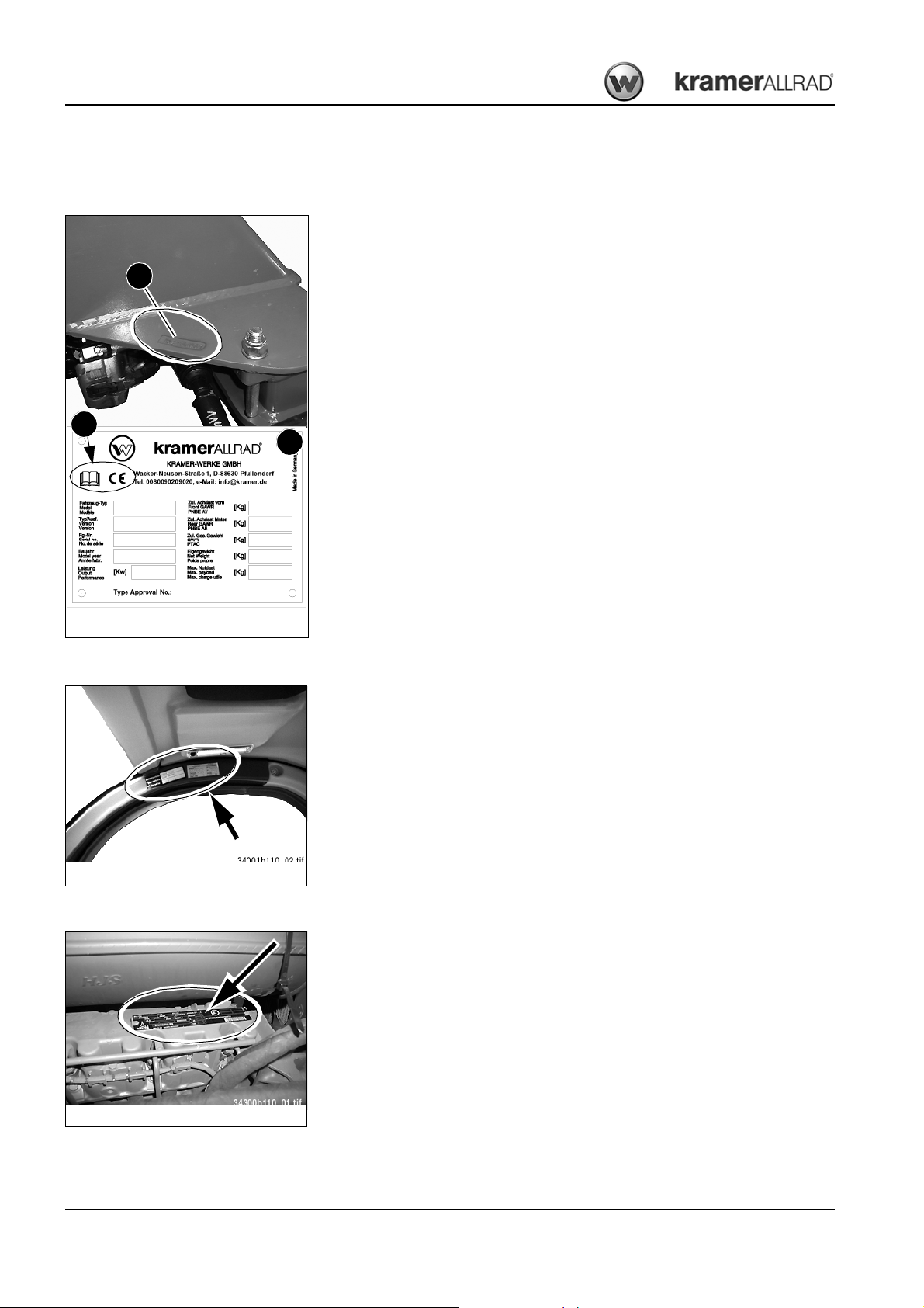
Introduction
Fig. 2: S erial nu mber, type label
A
B
C
6
7
8
9
10
1
2
3
4
5
Fig. 3: C ab type lab el
Fig. 4: Diesel engine type label
1.9 Type labels and component numbers
Serial number
The serial number is stamped on the machine frame A (next to the axle attachment, on the
right in driving direction). It is also located on type label B on the machine frame at the
front right (on the side of the loader unit bulkhead).
The CE mark C on the type label means that the machine meets the requirements of the
Machine Directive (2006/42 EC) and that the conformity procedure has been carried out.
Type label indications (example)
1
Machine model
2
Version
3
Serial no.
4
Year of construction
5
Output (kW)
6
Front gross axle weight rating (kg)
7
Rear gross axle weight rating (kg)
8
Gross weight rating (kg)
9
Dead weight (kg)
10
Maximum payload (kg)
351
351-01
351 01 0055
2010
45
4000
4000
6500
–
–
Cab number
Engine number
Other information – see chapter 6 “Specifications” on page 6-1
The type label (arrow) is located in the cab, at the top right in driving direction.
The type label (arrow) is located on the cylinder-head cover (engine).
Example: Deutz D 2011 L04 W
1-10 BA 35101/0 2/03 E N – Edition 1.0 * 35101_02 _03b110.f m
Page 31

Variable displacement pump number
Fig. 5: H ydraulic pump type label
Fig. 6: H ydraulic moto r type label
Fig. 7: R ear axle and gearbo x type lab el
Fig. 8: Front axle type label
The type label (arrow) is located on the hydraulic pump housing (next to where the pump is
installed on the diesel engine)
Variable displacement motor number
The type label (arrow) is located on the hydraulic motor, on the right in driving direction.
Introduction
Rear axle number
Front axle number
The type label (arrow) is located on the upper side of the differential housing, at the rear.
The type label (arrow) is located on the upper side of the differential housing, at the front.
BA 35101/02/ 03 EN – Edition 1.0 * 35101_02_03b110.fm 1-11
Page 32

Introduction
Fig. 9: Cab eye hook label
Fig. 10: Lab el for loading a nd tyin g down the machine
A B
XX
Fig. 11: Noi se level label
20
Fig. 12: Spe ed label
4030
Fig. 13: Dang er label
1.10 Description of labels and symbols
Labels on the outside of the machine
Cab eye hook label
The eye hooks on the cab are for removing the cab only and may not be used for crane
handling the machine – see chapter 3 “Crane handling the machine” on page 3-59 for further details.
Location
Cab roof (4x).
Label for loading and tying down the machine
Eye hooks for tying down the machine B during transport, and eye hooks A for lo ading the
machine.
➥ – see chapter 3 “Crane handling the machine” on page 3-59
➥ – see chapter 3 “Loading and transporting the machine on a transport vehicle” on
page 3-60
Location
On left and right of machine frame above the front axle attachment and at the rear under
the machine.
Noise level label
Noise levels produced by the machine.
➥ L
= sound power level – see chapter 6 “Noise levels” on page 6-12
WA
Location
On the rear window.
Label: maximum design-specific speed
Design-specific max. machine speed 20 kph (30/40 kph option)
Location
At the rear of the machine and on the left/right of the counterweight.
Label: general indication of danger
This label warns persons standing or working near the machine of an existing danger
within the area of increased danger around the machine.
Location
Front left and right of loader unit, and at rear of machine.
1-12 BA 35101/0 2/03 E N – Edition 1.0 * 35101_02 _03b110.f m
Page 33

Introduction
Fig. 14: Explanation of “Book” symbol
Fig. 15: Proh ibitive label: turning pa rts
Fig. 16: Label: fuel filler opening
Explanation of “Book” symbol
The “Book” symbol on a label means that the indications are explained in further detail in
the Operator's Manual.
Location
On labels.
Label: Danger of shearing!
Caution! Do not touch any moving or turning parts!
Carry out inspections and maintenance work only at engine standstill!
Location
In the area of the engine cooling (V-belt guard)
Label: fuel filler opening.
Use only the diesel fuels indicated.
• DIN EN 590 (EU)/ASTM D975-94 (USA)/EN 14214 (biodiesel)
• Do not use diesel fuel with additives
If other fuels are used, warranty rights shall not apply in case of diesel engine damage
(guarantee)!
Location
Near the filler inlet of the fuel tank (left-hand side of machine)
BA 35101/02/ 03 EN – Edition 1.0 * 35101_02_03b110.fm 1-13
Page 34

Introduction
Important!
Fig. 17: Loa d diagram
B
A
A
C
G
Fig. 18: Con trol lever la bel
E
DB
F
Labels inside the cab
Label: load diagram (A) for pallet forks and tyre pressure table
The framed weight indications state the maximum authorised load on the fork arms for
industrial and offroad applications.
The maximum load varies according to the distance between the load centre and the rear
end of the pallet forks.
Example on how to read the load diagram – see chapter 3 “Load diagram for pallet forks”
on page 3-89
The load diagram is valid only for applications with pallet forks!
• –seeAttachments with authorised material densities on page 1-5.
Observe the specific loads of other attachments used, e.g. rotary crane jib.
Label (B): tyre pressure table
List of authorised types of tyres with prescribed tyre inflation pressures.
➥– see chapter 6 “Tyres” on page 6-11
Location
Inside the cab, on left side of front window
Label: control lever (joystick) operation
• A = driving direction: (F) forwards (R) reverse and (N) neutral position
• B = additional control circuit with additional functions (option)
• C = automatic bucket repositioning (option) or front socket power supply
• D = locking/unlocking an attachment fitted on the quickhitch
• E = differential lock
• F = 4th control circuit (option)
• G = loader unit control pattern: raise/lower and dump in/out (optional float position)
Location
On the right-hand side window next to the control lever (joystick)
1-14 BA 35101/0 2/03 E N – Edition 1.0 * 35101_02 _03b110.f m
Page 35

Introduction
Fig. 19: Brake fluid label
A
B
Fig. 20: Operator 's Manual label
Fig. 21: Lab el: seat , fasteni ng the se at belt
Fig. 22: Lab el: read and underst and the s ervice manual
Brake fluid label
A = Caution! Do not fill in any water!
B = Use only LHM brake fluids!
• – see chapter 5 “Maintenance of the brake system” on page 5-23
• – see chapter 5 “Fluids and lubricants” on page 5-43
Location
On the trim next to the brake-fluid tank (left-hand side cab access)
Operator's Manual label
Caution! Read and understand this Operator's Manual before putting the machine into
operation, and before servicing or repairing it.
Location
On the right-hand side member inside the cab
Label: seat belt and machine stability
• Operate the machine only from the seat.
• Fasten the seat before operating the machine.
• Ensure machine stability.
• Read and understand the Operator's Manual
Location
On the right-hand side member inside the cab
BA 35101/02/ 03 EN – Edition 1.0 * 35101_02_03b110.fm 1-15
Label: Remove the ignition key!
Caution! Remove the ignition key before working on the machine.
• Read and understand the service manual
Location
On the right-hand side member inside the cab
Page 36

Introduction
Fig. 23: Proh ibitive label: no transp ort of pe rson s
Fig. 24: Proh ibitive label: no other perso ns allowed
Fig. 25: Labe l: load hoo k diagram (option)
N = 1900kgN = 1400kg
1000149082
346-01
AB
Fig. 26: Lab el for air con ditioning system refi ll (option)
Label: No transport of persons!
Warning! Lifting or transporting persons on the wheel loader, in the bucket or on the pallet
forks is prohibited.
Location
Inside the cab, on right side of front window.
. Label: No other persons allowed in the cab!
Warning! Carrying or transporting accompanying persons in the cab or on the wheel
loader is not allowed!
Location
In the cab (near the tool kit)
Label: load hook diagram (option)
Example: Maximum load capacity
• A Extended loader unit and quickhitch tilted in
➥Max N => 2200 kg
• B Extended loader unit and quickhitch
➥Max N => 1700 kg
Location
Inside the cab, on left side of front window
Label for air conditioning system refill (option)
Use only the refrigerants R 134a indicated on the label (see arrow) for refilling the air conditioning system.
Location
Inside the cab
1-16 BA 35101/0 2/03 E N – Edition 1.0 * 35101_02 _03b110.f m
Page 37

Labels in the engine compartment
Fig. 27: Lab el: hot fluid ( coolant)
Fig. 28: Lab el: hot s urface
Fig. 29: L abel: fil ler opening for hyd raulic oil
A B
Introduction
Label: Container under pressure, danger of burns!
The container is hot and under pressure. Do not open the container as long as it is still hot.
Open the container only after the coolant has cooled down
Open the cover carefully and slowly to allow the pressure to escape.
Location
In the engine compartment next to the expansion tank (coolant)
Label: Danger of burns!
Caution! Do not touch.
Location
On the rear wall of the engine compartment, on the left next to the exhaust silencer and
the filler inlet (hydraulic oil tank).
Label: filler opening for hydraulic oil
A = hydraulic oil or B = biodegradable hydraulic oil
➥ – see chapter 5 “Important information for the use of biodegradable oil” on
page 5-17
Location
On the rear wall of the engine compartment, on the left next to the filler inlet (hydraulic oil
tank)
BA 35101/02/ 03 EN – Edition 1.0 * 35101_02_03b110.fm 1-17
Page 38

Introduction
Notes:
1-18 BA 35101/0 2/03 E N – Edition 1.0 * 35101_02 _03b110.f m
Page 39

Danger!
Caution!
Important!
Environment!
Safe ty inst ructions
2 Safety instructions
2.1 Identification of warnings and dangers
Important indications regarding the safety of the staff and the machine are identified in this
Operator's Manual with the following terms and symbols:
Failure to observe the instructions identified by this symbol can result in
personal injury or death for the operator or other persons.
☞ Measures for avoiding danger to life and limb of the
operator or other people
Failure to observe the instructions identified by this symbol can result in
damage to the machine.
☞ Measures for avoiding danger for the machine
Safety instructions
This symbol identifies instructions for a more efficient and economical use of
the machine.
Failure to observe the instructions identified by this symbol can result in damage to the environment.
The environment is in danger if environmentally hazardous material (e.g.
waste oil) is not subject to proper use or disposal.
BA 35101/02/ 03 EN – Edition 1.0 * Sic herhei t_Radlader.fm 2-1
Page 40

Safety instructions
2.2 Designated use and exemption from liability
• Carrying or transporting accompanying persons in the cab or on the wheel
loader is not allowed! Carrying or transporting persons in the attachments (e.g.
bucket, pallet forks) is not allowed either!
• The machine may not be used for transport jobs on public roads!
• Fire hazard due to hot engine silencer – the machine may not be used in areas
posing a fire hazard (hay or straw storage facilities, etc.) !
• The machine is intended for:
• moving earth, gravel, coarse gravel or ballast and rubble, and for applications with
the attachments listed in chapter Introduction “Fields of application and using a wheel
loader with an attachment” on page 1-5!
• Every other application is regarded as not designated for the use of the machine. The
manufacturer will not be liable for damage resulting from use other than mentioned
above. The user alone will bear the risk.
Designated use also includes observing the instructions in the Operator's Manual and
observing the conditions of maintenance and service!
• Observe the pertinent regulations relevant to accident prevention, other generally
acknowledged regulations regarding safety and occupational medicine, as well as the
regulations and standards relevant to motor vehicles and traffic which are valid in your
country. Get informed on and follow the legal regulations of your country. The manufacturer shall not be liable for damage resulting from the failure to observe these regulations!
• The safety of the machine can be negatively affected by carrying out machine modifications without proper authority and by using spare parts, equipment, attachments and
optional equipment which have not been checked and released by the manufacturer.
The manufacturer will not be liable for damage resulting from this!
• The manufacturer shall not be liable for personal injury and/or damage to property
caused by failure to observe the safety instructions and the Operator's Manual, and by
the negligence of the duty to exercise due care when:
• handling
• operating
• servicing and carrying out maintenance work and
• repairing the machine. This is also applicable in those cases in which special
attention has not been drawn to the duty to exercise due care, in the safety instructions as well as in the operation and maintenance manuals (machine/engine).
• Read and understand the Operator's Manual before starting up, servicing or repairing
the machine. Observe the safety instructions!
• In applications with lifting gear, the machine is used according to its designated use
only if the prescribed devices are installed and functional!
2-2 B A 35101/02/03 EN – Edition 1.0 * Sicherheit_Rad lader.fm
Page 41

2.3 General conduct and safety instructions
Organisational measures
• The machine has been designed and built in accordance with state-of-the-art standards
and the recognised safety regulations. Nevertheless, its use can constitute a risk to life
and limb of the user or of third parties, or cause damage to the machine and to other
material property!
• The machine must only be used in technically perfect condition in accordance with its
designated use and the instructions set forth in the Operator's Manual, and only by
safety-conscious persons who are fully aware of the risks involved in operating the
machine. Immediately rectify any functional disorders, especially those affecting the
safety of the attachment!
Basic rule:
Before starting up the machine, inspect the machine for safety in work and road
operation!
• Careful and prudent working is the best way to avoid accidents!
• The Operator's Manual must always be at hand at the place of use of the machine, and
must therefore be kept in the storage compartment provided for in the cab.
Immediately complete or replace an incomplete or illegible Operator's Manual!
• In addition to the Operator's Manual, observe and instruct the operator in all other
generally applicable legal and other mandatory regulations relevant to accident
prevention and environmental protection.
These compulsory regulations may also deal with handling hazardous substances,
issuing and/or wearing personal protective equipment, or traffic regulations!
• With regard to specific operational features, e.g. those relevant to job organisation,
work sequences or the persons entrusted with the work, supplement the Operator's
Manual by corresponding instructions, including those relevant to supervising and
reporting duties!
• Persons entrusted with work on the machine must have read and understood the
Operator's Manual and in particular, chapter “Safety Instructions” before beginning
work. This applies especially to persons working only occasionally on the machine, e.g.
set-up or maintenance!
• The user/owner must check – at least from time to time – whether the persons
entrusted with operation or maintenance of the machine are working in compliance with
the Operator's Manual and are aware of risks and safety factors!
• The user/owner commits himself to operate and keep the machine in a perfect
condition, and, if necessary or required by law, to require the operating or servicing
persons to wear protective clothing etc.
• In the event of safety-relevant modifications or changes on the machine or of its
behaviour, stop the machine immediately and report the malfunction to the competent
authority/person.
Safety-relevant damage or malfunctions of the machine must be rectified immediately!
Safety instructions
BA 35101/02/ 03 EN – Edition 1.0 * Sic herhei t_Radlader.fm 2-3
Page 42

Safety instructions
• Never make any modifications, additions or conversions to the machine and its superstructures (e.g. cab, loader unit etc.), as well as to the attachments, which might affect
safety without the approval of the manufacturer! This also applies to the installation and
the adjustment of safety devices and valves, as well as to welding work on load-bearing
elements!
• Spare parts must comply with the technical requirements specified by the manufacturer. Original spare parts can be relied to do so!
• Replace hydraulic hoses within stipulated and appropriate intervals even if no safetyrelevant defects have been detected!
• Before working on or with the machine, remove jewellery, such as rings, wristwatches,
bracelets etc., and tie back long hair and do not wear loose-fitting garments, such as
unbuttoned or unzipped jackets, ties or scarves.
Injury can result from being caught up in the machinery or from rings catching on
moving parts!
• Keep the machine clean. This reduces
• Fire hazard, e.g. due to oil-soaked rags lying around
• Danger of injury, e.g. due to dirt or debris on the footholds, and
• Danger of accident e.g. due to dirt or debris on the brake or accelerator pedal!
• Observe all safety, warning and information signs and labels on the machine!
• Adhere to prescribed intervals or those specified in the Operator's Manual for routine
checks/inspections and maintenance work!
• Tools and workshop equipment adapted to the task on hand are absolutely indispensable for carrying out service, inspection, maintenance or repair work!
2-4 B A 35101/02/03 EN – Edition 1.0 * Sicherheit_Rad lader.fm
Page 43

Selection and qualification of staff, basic responsibilities
• Any work on or with the machine must be carried out by reliable staff only. Do not let
unauthorised persons drive or work with the machine! Observe statutory minimum age
limits!
• Employ only trained or instructed staff on the machine, and clearly and unequivocally
define the individual responsibilities of the staff for operation, set-up,
maintenance and repair!
• Define the machine operator's responsibilities – also with regard to observing traffic
regulations. Give the operator the authority to refuse instructions by third parties that
are contrary to safety!
• Do not allow persons to be trained or instructed or persons taking part in a general
training course to work on or with the machine without being permanently supervised
by an experienced person!
• Work on the electrical system and equipment, on the chassis and the steering and
brake systems must be carried out only by technical staff which has been specially
trained for such work.
Work on the hydraulic system of the machine must be carried out only by staff with
special knowledge and experience in hydraulic systems!
• Seal off the danger area should it not be possible to keep a safe distance.
• Stop work if persons do not leave the danger area in spite of warning! Keep out of the
danger area!
Danger area:
The danger area is the area in which persons are in danger due to the
movements of the
• Machine
• work equipment
• other equipment or load!
• This also includes the area affected by falling material, equipment or by parts which
are thrown out.
• The danger area must be extended accordingly in the immediate vicinity of buildings,
scaffolds or other elements of construction!
Safety instructions
BA 35101/02/ 03 EN – Edition 1.0 * Sic herhei t_Radlader.fm 2-5
Page 44

Safety instructions
2.4 Safety instructions regarding operation
Normal operation
• Avoid any operational mode that might be prejudicial to safety!
• Before beginning work, familiarise yourself with the surroundings and circumstances of
the work site. These are e.g. obstacles in the working and travelling area, the loadbearing capacity of the ground and any necessary barriers separating the work site
from public roads!
• Take the necessary precautions to make sure the machine is used only when in a safe
and reliable state!
Operate the machine only if all protective and safety-oriented devices, e.g. removable
safety-devices, soundproofing elements and exhausters etc., are in place and fully
functional!
• Check the machine at least once a day/per work shift for visible damage and defects.
Report any changes (incl. changes in the machine's working behaviour) to the
competent organisation/person immediately! If necessary, stop the machine immediately and lock it!
• In the event of malfunctions, stop the machine immediately and lock it! Have any
defects rectified immediately!
• Start and operate the machine from the seat only!
• Before leaving the seat, apply the parking brake and stop the diesel engine!
• Carry out start-up and shut-down procedures in accordance with the Operator's
Manual, and observe the telltales!
• Before putting the machine/attachment into operation (start-up/moving), make sure
nobody is at risk by putting the machine/attachment into operation!
• Before driving with the machine, and also after interrupting work, check whether the
brakes, the steering, signalling and light systems are functional!
• Before moving the machine always check whether the supplementary equipment and
the attachments have been safely stowed away or attached!
• When driving on public roads, ways and places, observe the valid traffic regulations
and, if necessary, make sure beforehand that the machine is in a condition perfectly
compatible with these regulations!
• Always switch on the lights in conditions of poor visibility and after dark!
• No raising, lowering or carrying persons in the work equipment/attachments!
• Installing a man basket or a working platform is prohibited!
(Always contact Kramer-Werke GmbH for installation!)
• When crossing underpasses, bridges and tunnels, or when passing under overhead
lines always make sure there is enough clearance!
• Always keep at a safe distance from the edges of building pits and slopes!
• When working in buildings or in enclosed areas, look out for:
• Height of the ceiling/clearances
• Width of entrances
• Maximum load of ceilings and floors
• Sufficient room ventilation – danger of poisoning!
2-6 B A 35101/02/03 EN – Edition 1.0 * Sicherheit_Rad lader.fm
Page 45

Safety instructions
• Avoid any operation that might be a risk to machine stability!
• During operation on slopes, drive or work uphill or downhill. If driving across a slope
cannot be avoided, bear in mind the tilting limit of the machine!
Always keep the attachments/work equipment close to the ground. This also applies to
driving downhill!
When driving or working across a slope, the load must be on the uphill side of the
machine!
• On sloping terrain always adapt your drive speed to the prevailing ground conditions!
Never change to lower gear on a slope but always before reaching it!
• Before leaving the seat always secure the machine against unintentional movement
and unauthorised use!
Lower the work equipment/attachments to the ground
• Before starting work check whether:
• all safety devices are properly installed and functional
• and an approved warning triangle, hazard warning light and first aid kit are at hand!
• Before moving the machine or before taking up work:
• Make sure visibility is sufficient (do not forget rearview mirrors!)
• Adjust correct seat position (you must be able to press the brake pedal as far as it will
go).
Never adjust the seat when driving or working!
• Fasten your seat belt
• Inspect the immediate area (children!)
In the work area the operator is responsible for third parties!
• Caution when handling fuel – increased danger of fire!
Make sure fuel does not come into contact with hot parts!
Do not smoke during refuelling, and avoid fire and sparks! Stop the engine during
refuelling and do not smoke!
• Never get on or off a moving machine! Never jump off the machine!
• Should the lights of the machine not be sufficient for carrying out work safely, provide
additional lighting of the work area!
• Installed work lights must not be switched on for travel on public roads. They can be
switched on in work operation if users of public roads are not dazzled!
• Hydrostatic 4 wheel steering takes time getting used to it. Therefore, adjust the drive
speed to your abilities and the circumstances. Selection and change of steering mode
at machine standstill only!
BA 35101/02/ 03 EN – Edition 1.0 * Sic herhei t_Radlader.fm 2-7
Page 46

Safety instructions
Applications with lifting gear
Definition:
Applications with lifting gear are understood as procedures involving raising, transporting
and lowering loads with the help of slings and load-securing devices (e.g. ropes, chains).
In doing so, the help of persons is necessary for securing and detaching the load. This
applies for example to raising and lowering pipes, shaft rings or containers!
• The machine may be used for applications with lifting gear only if the prescribed safety
devices are in place and functional.
These are e.g.:
• Safe possibilities of slinging and securing lifting gear (load hook)
• Load diagram!
• The load must be secured so as to prevent it from falling or slipping!
• Persons guiding the load or securing it must stay in visual contact with the machine
operator!
• The machine operator must guide the load the nearest possible to the ground and
avoid any oscillating or swinging movements!
• The machine may be moved with a raised load only if the path of the machine is as
level as possible!
• The persons attaching or securing loads may approach the boom from the side only,
and only after the machine operator has given his permission. The machine operator
may give his permission only after the machine is at a standstill and the work
attachment no longer moves!
• Do not use any lifting gear (ropes, chains) which is damaged or not sufficiently dimensioned. Always wear protective gloves when working with lifting gear!
2-8 B A 35101/02/03 EN – Edition 1.0 * Sicherheit_Rad lader.fm
Page 47

Trailers and attachments
Safety instructions
• Prior to driving on public roads remove all attachments which cannot be secured in
compliance with the legal regulations of your country!
• Get informed on the legal regulations of your country which deal with the use and applications of trailers towed by the machine!
• Trailer operation with the towing device of the machine is not permitted!
• Attachments and counterweights affect handling, as well as the steering and brake
capability of the machine!
• Fit the attachments with the specially required devices only!
• Before uncoupling or coupling hydraulic lines (hydraulic quick couplers):
• Stop the engine
• Release the pressure in the hydraulic system. In order to do so, move the control
levers of the hydraulic control units back and forth a couple of times!
• Coupling attachments requires special care!
• Secure the attachments against unintentional movement!
• Operate the machine only if all protective facilities have been installed and are
functional, and if all brake, light and hydraulic connections have been connected!
• If optional equipment is installed, all additionally required light installations, telltales
etc., must be provided for and functional!
• Mount the attachments only if the engine and the drive have been switched off!
• Especially when driving or working with machines equipped with a quickhitch for the
attachments, make sure the attachment is safely locked in the quickhitch. The lock pin
must be visible on either side of the bores on the attachment. Check before starting
work!
• Prior to fitting attachments to the loader unit, secure the control lever of the hydraulic
control unit against unintentional movement!
• Be careful when coupling attachments to the loader unit: danger of personal injury due
to crushing and shearing. Make sure nobody is between the machine and the
attachment without securing the machine and the attachment against movement!
Transporting, towing, loading
• The machine must be towed, loaded and transported only in accordance with the
Operator's Manual!
• For towing the machine observe the prescribed transport position, admissible speed
and itinerary!
• Use only suitable means of transport and lifting gear of adequate capacity/payload!
• Safely secure the machine on means of transport! Use suitable slinging points and
load-securing devices!
• The recommissioning procedure must be strictly in accordance with the Operator's
Manual!
BA 35101/02/ 03 EN – Edition 1.0 * Sic herhei t_Radlader.fm 2-9
Page 48

Safety instructions
2.5 Safety instructions for maintenance
• Avoid any operational mode that might be prejudicial to safety!
• Observe the adjustment, maintenance and inspection activities and intervals set forth in
the Operator's Manual, including information on the replacement of parts/partial
equipment!
These activities may be carried out by technical staff only!
• The machine may not be serviced, repaired or test-driven by unauthorised staff!
• Brief operating staff before beginning special operations and maintenance work!
Appoint a person to supervise the activities!
• In any work concerning the operation, conversion or adjustment of the machine and its
safety-oriented devices, or any work related to maintenance, inspection and repair,
observe the start-up and shut-down procedures set forth in the Operator's Manual, and
the information on maintenance work
• If required, secure the maintenance area appropriately!
• Prior to carrying out service, maintenance and repair work, attach a warning label, such
as “Repair work – do not start machine!”, to the ignition lock/steering wheel or to the
control elements.
Remove the ignition key!
• Carry out service, maintenance and repair work only if the
• machine is positioned on firm and level ground
• lever for selecting the driving direction is in neutral
• parking brake is applied
• all hydraulically movable attachments and working equipment have been lowered to
the ground
• engine is stopped
• ignition key is removed and the
• machine has been secured against unintentional movement!
• Should maintenance or repair be inevitable with the engine running:
• Only work in groups of two
• Both persons must be authorised for the operation of the machine
• One person must be seated on the seat and maintain visual contact with the other
person
• Observe the specific safety instructions in the work manual
• Keep a safe distance from all rotating and moving parts, e.g. fan blades, V-belt
drives, PTO shaft drives, fans etc.!
• Prior to carrying out assembly work on the machine, make sure no movable parts will
roll away or start moving!
• To avoid the risk of accidents, parts and large assemblies being moved for replacement
purposes must be carefully attached and secured to lifting gear.
Use only suitable lifting gear and suspension systems in a technically perfect state with
adequate load-bearing capacity!
Stay clear of suspended loads!
• The brake and steering systems are crucial to safety. Maintenance work must be
carried out by trained staff and an authorised workshop only!
2-10 BA 35101/0 2/03 EN – Edition 1.0 * Sich erheit_Radlader .fm
Page 49

Safety instructions
• Have loads fastened and crane operators instructed by experienced persons only!
The person giving the instructions to the operator must be within sight or sound of him!
• Always use specially designed or otherwise safety-oriented ladders and working
platforms to carry out overhead assembly work.
Never use machine parts or attachments/superstructures as a climbing aid!
Wear a safety harness when carrying out maintenance work at greater heights!
Keep all handles, steps, handrails, platforms, landings and ladders free from dirt, snow
and ice!
• Clean the machine, especially connections and threaded unions, of any traces of oil,
fuel or preservatives before carrying out maintenance/repair work!
Do not use aggressive detergents!
Use lint-free cleaning rags!
• Before cleaning the machine with water, steam jet (high-pressure cleaner) or detergents, cover or tape up all openings which – for safety and functional reasons – must
be protected against water, steam or detergent penetration. Special care must be taken
with the electrical system!
• After cleaning, remove all covers and tapes applied for that purpose!
• After cleaning, examine all fuel, lubricant and hydraulic oil lines for leaks, chafe marks
and damage!
Rectify all defects without delay!
• Always tighten any screwed connections that have been loosened during maintenance
and repair!
• Any safety devices removed for set-up, maintenance or repair purposes must be
refitted and checked immediately upon completion of the maintenance and repair work!
• Make sure all consumables and replaced parts are disposed of safely and with
minimum environmental impact!
• Do not use the work equipment as lifting platforms for persons!
• Before taking up work on machine parts dangerous for life and limb (bruising, cutting),
always ensure safe blocking/support of these areas!
• Carry out maintenance and repair work beneath a raised machine, work equipment/
attachments or additional equipment only if a safe and secure support has been
provided for (the sole use of hydraulic rams, jacks etc. does not sufficiently secure
raised machines or equipment/attachments)!
• Avoid contact with hot parts, such as the engine block or the exhaust system during the
operation of the machine and for some time afterwards – danger of burns!
• Retainer pins can fly out or splinter when struck with force – danger of personal injury!
• Do not use starting fuel! This especially applies to those cases in which a heater plug
(intake-air preheating) is used at the same time – danger of explosions!
• Apply special care when working on the fuel system – increased danger of fire!
BA 35101/02/ 03 EN – Edition 1.0 * Sic herhei t_Radlader.fm 2-11
Page 50

Safety instructions
2.6 Maintenance work on protective ROPS and FOPS structures
Cab, roll-over bar, protective screen
• Straightening and welding work on cabs, roll-over bars and protective screens are
prohibited. These structures must be replaced by original spare parts from the
manufacturer!
• Drilling holes or modifying protective ROPS/FOPS structures is prohibited!
• Driving or working with the wheel loader without installing the protective ROPS/FOPS
structures correctly is prohibited!
2.7 Warning of special hazards
Electric energy
• Use only original fuses with the specified current rating!
Switch off the machine immediately and rectify the malfunction if trouble occurs in the
electrical system!
• When working with the machine, maintain a safe distance from overhead electric lines!
If work must be carried out close to overhead lines, the equipment/attachments must be
kept well away from them. Caution, danger! Get informed on the prescribed safety
distances!
• If your machine comes into contact with a live wire
• Do not leave the machine
• Drive the machine out of the danger area
• Warn others against approaching and touching the machine
• Have the live wire de-energised
• Do not leave the machine until the line that has been touched or damaged has been
safely de-energised!
• Work on the electrical system may only be carried out by a technician with appropriate
training, in accordance with the applicable electrical engineering rules!
• Inspect and check the electric equipment of the machine at regular intervals. Defects
such as loose connections or scorched cables must be rectified immediately!
• Observe the operating voltage of the machine/attachments!
• Always remove the earthing strap from the battery when working on the electrical
system or when carrying out welding work!
• Starting with a battery jump cable can be dangerous if carried out improperly. Observe
the safety instructions regarding the battery!
Gas, dust, steam, smoke
• Operate the machine only on adequately ventilated premises! Before starting internal
combustion engines or operating fuel-operated heating systems on enclosed premises,
make sure there is sufficient ventilation!
Observe the regulations in force at the respective site!
• Carry out welding, flame-cutting and grinding work on the machine only if this has been
expressly authorised. There can be a risk of explosion and fire, for example!
• Before carrying out welding, flame-cutting and grinding work, clean the machine and its
surroundings from dust and other inflammable substances, and make sure the
premises are adequately ventilated – danger of explosions!
2-12 BA 35101/0 2/03 EN – Edition 1.0 * Sich erheit_Radlader .fm
Page 51

Hydraulics
• Work on the hydraulic equipment of the machine must be carried out only by persons
having special knowledge and experience in hydraulic systems!
• Check all lines, hoses and screwed connections regularly for leaks and obvious
damage! Repair any damage and leaks immediately! Splashed oil can cause injury and
fire!
• In accordance with the Operator's Manual/instructions for the respective assembly,
release the pressure in all system sections and pressure lines (hydraulic system) to be
opened before carrying out any implementing/repair work!
• Hydraulic and compressed-air lines must be laid and fitted properly. Make sure no
connections are interchanged. The fittings, lengths and quality of the hoses must
comply with the technical requirements!
Noise
• During operation all sound baffles must be closed!
• Wear ear protectors if necessary!
Oil, grease and other chemical substances
• When handling oil, grease and other chemical substances (e.g. battery electrolyte –
sulphuric acid), observe the product-related safety regulations (safety data sheet)!
• Be careful when handling hot consumables – risk of burning or scalding!
Safety instructions
Battery
Tyres
• When handling the battery observe the specific safety instructions and regulations
relevant to accident prevention. Batteries contain sulphuric acid – caustic!
• Especially when charging batteries, as well as during normal operation of batteries, an
oxyhydrogen mixture is formed in the battery cells – danger of explosion!
• In the case of a frozen battery or of an insufficient electrolyte level, do not try start-up
with a battery jump cable. The battery can burst or explode!
• Repair work on tyres and rims must be carried out by technical staff or by an authorised
workshop only!
• Damaged tyres and/or wrong tyre pressure reduce the operational safety of the
machine. Therefore carry out regular checks of the tyres for
• Prescribed tyre pressure and
• Damage!
• Do not inflate tyres with inflammable gas – danger of explosion! Check the wheel nuts
once a day for tightness. After changing wheels, retighten the wheel nuts after
10 service hours!
BA 35101/02/ 03 EN – Edition 1.0 * Sic herhei t_Radlader.fm 2-13
Page 52

Safety instructions
Notes:
2-14 BA 35101/0 2/03 EN – Edition 1.0 * Sich erheit_Radlader .fm
Page 53

Operation
Operation
3 Operation
3.1 Description of control elements
This chapter describes the controls, and contains information on the function and the handling of the telltales and controls in the cab.
The pages stated in the table refer to the description of the controls.
A combination of digits, or a combination of digits and letters (e.g. 40/18 or 40/A) used for identifying the control elements, means:
fig. no. 40/control element no. 18 or position A in fig. no. 40
Figures carry no numbers if they are placed to the left of the text.
You can unfold pages (3-2 and/or 3-4) for a better overview.
The symbols used in the description have the following meanings:
• This symbol stands for a list
• Subdivision within lists or an activity. Follow the steps in the recommended sequence
☞ This symbol requires you to carry out the activity described
➥ Description of the effects or results of an activity
n. s. = not shown
“Option” = optional equipment
Stated whenever controls or other components of the machine are installed as an option.
Cab overview: see overleaf
BA 35101/02 /03 EN – Edition 1.0 * * 35201_02b310.fm 3-1
Page 54

Operation
37
36
35
34
33
32
31
30
29
28
27
26
23
3.2 Cab overview
Inside of cab (overview) For more information see page
1 3 4 5238 39 5
6
7
8
9
D
P
F
1
4
A
6
R
I
2
A
U
T
O
8
0
O
F
0
I
1
b
0
F
a
r
10
11
12
13
14
15
16
192021222425 1823
17
1 Sun visor
2 Board – relays and fuses (left) ............................................................................................... ...................................................
3 Front window wiper motor ................................................................................................................................................. 3-49
4 Interior light ....................................................................................................................................................................... 3-44
5 Front working light............................................................................................................................................................. 3-43
6 Board – relays and fuses (right) ................................................................................................................................................
7 Steering column adjustment lever..................................................................................................................................... 3-30
8 Steering electronics
9 Front window air vents (left/right) ..................................................................................................................................... 3-46
10 Lights................................................................................................................................................................................. 3-43
11 Fresh air filter for heating.................................................................................................................................................. 3-46
12 Instrument panel – fresh air, heating (air conditioning option) .......................................................................................... 3-46
13 12 V socket
14 Proportional electronics control valve
15 Control lever (joystick)....................................................................................................................................................... 3-62
16 Accelerator pedal .............................................................................................................................................................. 3-34
17 Fire extinguisher (option) .................................................................................................................................................. 3-14
18 Parking brake lever........................................................................................................................................................... 3-36
19 Preheating start switch...................................................................................................................................................... 3-16
20 Prepared installation for radio (option)
21 Joystick lock (stop cock) for road travel ............................................................................................................................ 3-26
22 Seat belt............................................................................................................................................................................ 3-53
23 Loudspeakers (option)
24 Brake/inching pedal........................................................................................................................................................... 3-35
25 Storage net for Operator's Manual
26 Rear window wiper motor.................................................................................................................................................. 3-49
27 Fixture – first-aid kit
28 Tank – washer system ...................................................................................................................................................... 3-49
29 Storage compartment
30 Tool kit
31 Left/right-hand side door arrester...................................................................................................................................... 3-13
32 Seat................................................................................................................................................................................... 3-50
33 Coolant level sensor amplifier
34 Rear working light ............................................................................................................................................................. 3-43
35 Hook
36 Aerial (option)
37 Rotating beacon (option)................................................................................................................................................... 3-45
38 Brake fluid tank
39 Multifunctional lever – turn indicators, wipers, horn .......................................................................................................... 3-45
Fig. 30: Cab overview
3-2 BA 35101/02 /03 EN – Edition 1.0 * 35201_02b3 10.fm
Page 55

Operation
Instrument panel overview: see overleaf Instrument panel overview: see overleaf
BA 35101/02 /03 EN – Edition 1.0 * * 35201_02b310.fm 3-3
Page 56

2
46
8
0
AIR
bar
10
1
DPF
I
0
O
F
F
A
U
T
O
Operation
44
43
42
41
40
77
76
75
74
90
91
45 4746
78
80
79
Fig. 33: Indicating instrument overview
Fig. 35: M ultifunctiona l lever
103 104
105
48 49
81
82
39
106
83
50
86
84
85
51
52
58
53
57
54
56
55
Fig. 31: Rig ht-hand side switch panel
67
66
65
Fig. 34: Swi tch panel for heating
94 95 96 97 98
93
92
60 61
59
70 71
69
68
Fig. 32: Left -hand side swi tch pane l
87 88 89
62
63
64
72
73
3.3 Instrument panel, multifunctional lever and drive lever (overview)
Indicating instrument console For more information see page
40 Not assigned
41 Hydraulic oil temperature gauge ........................................................................................................................................5-16
42 Telltale (red/yellow/green) – diesel particle filter (option)...................................................................................................5-36
43 Telltale (green) – front socket (option) ...............................................................................................................................3-42
44 Telltale (yellow) – accelerator pedal lock (option)..............................................................................................................3-34
45 Hose burst valve, load stabiliser (option) telltale (yellow) ........................................................................................ 3-40, 3-98
46 Diesel engine temperature telltale (red) ...............................................................................................................................5-5
47 Telltale (green) – not assigned
48 Steering synchronisation telltale (red)................................................................................................................................3-31
49 Telltale (green) – diagonal steering (crab steering option).................................................................................................3-33
50 Telltale (green) – front axle steering ..................................................................................................................................3-32
51 Forwards driving direction telltale (green) ..........................................................................................................................3-38
52 4 wheel steering telltale (green) .........................................................................................................................................3-32
53 Reverse driving direction telltale (green)............................................................................................................................3-38
54 Diesel engine temperature gauge (115 °C ON with acoustic warning/110 °C OFF) ...........................................................5-9
55 Speedometer (high speed option)
Switch console on the right For more information see page
56 Not assigned
57 Switch (grey) – heated rear window, mirror heating (option)
58 Not assigned (reversing fan option)
59 Not assigned
60 Tip switch (blue) – steering synchronisation ......................................................................................................................3-31
61 Switch (grey) – diagonal steering (crab steering option) ....................................................................................................3-33
62 Switch with lock (blue) – 4 wheel/front axle steering..........................................................................................................3-32
63 Speed range selection switch (blue) ..................................................................................................................................3-37
64 Switch (grey) – rear wiper ..................................................................................................................................................3-49
Switch console on the left For more information see page
65 Not assigned – quickhitch lock (option only for telescopic boom)
66 Switch (green) – load stabiliser (option) .............................................................................................................................3-40
67 Switch (grey) – rear working light.......................................................................................................................................3-43
68 Lights switch (grey) ............................................................................................................................................................3-44
69 Hazard warning system switch (red) ..................................................................................................................................3-45
70 Switch (grey) – front working light...................................................................................................................................... 3-44
71 Front socket (option) tip switch (grey)................................................................................................................................3-42
72 Switch (grey) – rotating beacon (option) ............................................................................................................................3-45
73 Not assigned – overload cutoff and emergency lowering (option only for telescopic boom)
107
99
102
101
15
21
100
Fig. 36: Control lever (joystick)
Fig. 37: Rig ht-hand side console (overview)
3-4 B A 35101/02/03 EN – Edition 1.0 * 352 01_02b31 0.fm
Page 57

Operation
Operation
Indicating instrument For more information see page
74 Hour meter
75 Right/left turn indicators telltale (green) for rear attachments ............................................................................................3-45
76 Right/left turn indicators telltale (green) .............................................................................................................................3-45
77 Coolant level telltale (red) ....................................................................................................................................................5-9
78 Hydraulic oil filter telltale (red)............................................................................................................................................5-16
79 Air filter telltale (yellow) ......................................................................................................................................................5-11
80 Alternator charge function telltale (red)..............................................................................................................................5-32
81 Parking brake telltale (red) .................................................................................................................................................3-35
82 Engine oil pressure telltale (red) ..........................................................................................................................................5-5
83 Telltale (red) – 3rd control circuit, continuous operation ....................................................................................................3-64
84 High beam telltale (blue) ....................................................................................................................................................3-44
85 Cold starter telltale (yellow)................................................................................................................................................3-16
86 Tank gauge (fuel)
Heating switch console (optional air conditioning) For more information see page
87 Rotary switch – heater fan .................................................................................................................................................3-46
88 Rotary switch – heating temperature .................................................................................................................................3-46
89 Air conditioning (option) switch (grey) ................................................................................................................................3-48
Multifunctional lever turn indicators, wipers, horn For more information see page
90 Horn tip switch....................................................................................................................................................................3-45
91 Rotary switch and tip switch – front wiper, washer pump ..................................................................................................3-45
Switch console (armrest) For more information see page
92 Tip switch – accelerator pedal lock (option) .......................................................................................................................3-34
93 Crawler gear potentiometer/low-speed control (option) .....................................................................................................3-39
94 Switch with lock (green) – 3rd control circuit lock ..............................................................................................................3-63
95 Switch with lock (green) – continuous operation of 3rd control circuit (option) ..................................................................3-64
96 Switch (green) – front additional control circuit (option) .....................................................................................................3-95
97 Switch (green) – rear additional control circuit (option) ......................................................................................................3-95
98 Tip switch (green) – raise/lower hydraulic tipper (option only for trailer operation)
99 Switch – tilt ram lock (option)
Control lever (joystick) For more information see page
100 Not assigned
101 Switch – unlock/lock 3rd control circuit ..............................................................................................................................3-63
102 Tip switch – driving direction in neutral ..............................................................................................................................3-37
103 Switch – forwards/reverse driving direction........................................................................................................................3-38
104 Tip switch – additional control circuit with additional functions (option) .............................................................................3-95
105 Tip switch – additional control circuit with additional functions (option) .............................................................................3-95
106 Front socket tip switch (option) or bucket repositioning (option) ..............................................................................3-42, 3-94
107 Switch (scroll wheel) – additional control circuit (4th control circuit proportional controls option)......................................3-97
BA 35101/02/ 03 EN – Edition 1.0 * 35201_02b320.fm 3-5
Page 58

Operation
Caution!
Caution!
82
77
80
76
75
84
3.4 Functional description: telltales
Telltale check
All telltales come on briefly for a check when the ignition is switched on.
For your own safety and in order to avoid consequential damage to the
machine, have defective telltales immediately checked or replaced by an
authorised workshop!
Telltales and warning lights on the indicating instrument
Engine oil pressure telltale (red)
Comes on if the engine oil pressure is too low. In this case:
☞ Stop the machine
☞ Stop the engine immediately and check the oil level – see chapter 5 “Checking the
engine oil level” on page 5-5
Coolant level telltale (red)
Danger of engine breakdown if the telltale comes on with the engine running!
☞ Stop engine immediately
☞ Check the coolant level – see chapter 5 “Checking the coolant level” on
page 5-9
Alternator charge function telltale (red)
The telltale comes on when the ignition is turned on and goes out as soon as the engine
runs.
The V-belt or the charging circuit of the alternator is faulty if the telltale comes on with the
engine running. The battery is no longer charged.
Right/left turn indicators telltale (green)
Flashes intermittently when the turn indicators are used
Right/left turn indicators telltale (green) on rear attachment
Flashes intermittently when the turn indicators are used and a front or rear attachment is
connected electrically.
High beam telltale (blue)
Comes on if high beam is switched on, or during headlight flashing.
3-6 BA 35101/ 02/03 EN – Edition 1.0 * 35201_02b320.f m
Page 59

Operation
P
81
78
79
83
85
54
41
42
43
44
Parking brake telltale (red)
Comes on when the parking brake is applied.
The electric driving interlock prevents starting the engine with the parking brake applied.
Hydraulic oil filter telltale (red)
Indicates inadmissibly high pressure in the hydraulic reflux line to the tank. In this case:
☞ Have the hydraulic oil reflux filter checked and, if necessary, replaced by an authorised
workshop
Air filter telltale (yellow)
☞ Indicates air filter contamination.
Telltale (red) – continuous operation of 3rd control circuit (hydraulics)
Comes on during operation of an attachment with its own hydraulic circuit (e.g. rotary
broom with hydraulic motor).
Telltale (yellow) – preheating time lag relay
Comes on when the key in preheating start switch is in position 1.
➥ A glow plug preheats the intake air of the diesel engine during this time.
Telltales and indicators on the instrument panel
Temperature gauge with acoustic warning – engine (coolant)
Indicates the engine temperature detected by a sensor.
Engine temperature should be between 80 and 105 °C.
• Max. admissible temperature is 110 °C.
• The acoustic warning sounds from 115 °C
• – see chapter 5 “General instructions regarding cooling system maintenance” on
page 5-7
Hydraulic oil temperature gauge
Indicates the hydraulic oil temperature detected by a sensor.
• – see chapter 5 “Monitoring the hydraulic oil and the reflux filter” on page 5-15
Telltale (red/yellow/green) – diesel particle filter (option)
The LED indicates the status in the exhaust gas particulate filter system.
➥ – see chapter 5 “Checking the electronic filter monitoring” on page 5-38
Telltale (green) – front socket (option)
The LED indicates whether electrically operated attachments are connected.
Telltale (yellow) – accelerator pedal lock (option)
Indicates that the accelerator pedal lock is switched on (manual throttle).
BA 35101/02/ 03 EN – Edition 1.0 * 35201_02b320.fm 3-7
Page 60

Operation
45
46
47
48
49
50
52
53 51
Telltale (yellow) – hose burst valve/load stabiliser (option)
Indicates that the load stabiliser is switched on, and that the hose burst valve is disabled.
➥ –seeLoad stabiliser (option) on page 3-40 and “Hose burst valve” safety feature
(option) on page 3-98
Telltale (red) – hydraulic oil temperature
Indicates that the temperature in the hydraulic system is too high.
➥ – see chapter 5 “Monitoring the hydraulic oil and the reflux filter” on page 5-15
Telltale (green) – differential lock
Indicates that the differential lock is switched on
Telltale (red) – steering synchronisation
Indicates that the wheels on both axles are aligned.
Telltale (green) – diagonal steering (crab steering option)
Indicates that diagonal steering is switched on
Telltale (green) – front axle steering (option)
Indicates that front axle steering is switched on
4 wheel steering telltale (green)
Indicates that 4 wheel steering is switched on
Telltale (green) – driving direction
Indicates forwards or reverse driving direction
3-8 BA 35101/ 02/03 EN – Edition 1.0 * 35201_02b320.f m
Page 61

3.5 Putting the wheel loader into service
Safety instructions regarding commissioning
• Only use the steps and handles when entering and leaving the cab
• Face the machine as you enter and leave it
• Never use the controls or movable lines and cables as handles
• Keep the footholds and the handles clean to ensure a safe hold at all times
• Immediately remove dirt, such as oil, grease, earth, snow or ice
• Never get on or off a moving machine! Never jump off the machine
• Stop the diesel engine and apply the parking brake before leaving the wheel loader
• Always observe the warning and information labels, and the load diagrams (e.g.
pallet forks) of the loader unit
Important information for the operating staff
• The operating staff (driver) must have read and understood this Operator's Manual
before putting the machine into operation
• The machine may be put into operation by authorised staff only
➥ – see chapter 1 “Driving licence” on page 1-8 and – see chapter 2 “Selection and
qualification of staff, basic responsibilities” on page 2-5 of this Operator's Manual.
• The machine may only be put into operation when the driver is seated
• Carrying or transporting accompanying persons in the cab or on the wheel
loader is not allowed
• The machine may only be used in technically perfect condition in accordance with its
designated use and the instructions set forth in the General Certification for Vehicles
(Germany), the data confirmation (Germany) and in the Operator's Manual, and only by
persons who are fully aware of the risks involved in operating the machine
• Run through the checklists in the following tables
Operation
Running-in period of wheel loader
Handle the machine carefully during its first 100 operating hours.
Observe the following recommendations during the running-in period.
• Do not overload the machine, but at the same time do not drive too cautiously either, as
the machine will never reach its proper operating temperature
• Do not run the engine at high speed for extended periods
• Increase the load gradually while varying the engine speed
• Never let the engine run at idling speed for longer time –seeStarting the engine on
page 3-16
• Strictly observe maintenance schedules and carry out (or have carried out) the
specified maintenance work – see chapter 5 “Maintenance plan” on page 5-47
BA 35101/02/ 03 EN – Edition 1.0 * 35201_02b320.fm 3-9
Page 62

Operation
3.6 Checklist
Starting checklist
These checklists cannot claim to be exhaustive; they are merely intended as an aid for you
in fulfilling your duties as a conscientious operator.
The checking and monitoring jobs listed below are described in greater detail in subsequent chapters of the Operator's Manual.
If the answer to one of the following questions is NO, first rectify the cause of the fault
before starting or continuing work.
Check the following points before putting the machine into service or starting the engine:
No. Starting checklist ✔
1 Enough fuel in the tank? (➠ 5-3)
2 Engine oil level OK? (➠ 5-5)
3 Oil level in hydraulic tank OK? (➠ 5-16)
4 Water level in washer tank OK? (➠ 3-2)
5 V-belt condition and tension checked? (➠ 5-13)
6 Loader unit lubricated? (➠ 5-20)
7 Brake system (including parking brake) OK? (➠ 3-35)
8 Tyre condition and inflation pressure OK? (➠ 5-24, 6-11)
Wheel nuts safely tightened (especially after a wheel change)?
9
(➠ 6-13)
Lights, signals, indicators, warning lights and telltales OK?
10
(➠ 3-43, 3-45, 3-6)
11 Windows, mirrors, lights and steps clean?
12 Attachment on the loader unit safely locked? (➠ 3-63)
13 Engine cover safely locked? (➠ 3-14)
Especially after cleaning, maintenance or repair work:
14
Rags, tools and other loose objects removed?
Approved warning triangle, hazard warning light and first aid kit in the
15
machine?
16 Seat position and rearview mirrors correctly adjusted? (➠ 3-50)
17 Seat belt fastened? (➠ 3-53)
3-10 BA 35101/ 02/03 EN – Edition 1.0 * 35201_02b320.f m
Page 63

Operation checklist
Operation
After starting the engine and during operation, check and observe the following points:
No. Operation checklist ✔
Telltales for engine oil pressure and alternator gone out?
1
(➠ 3-16)
2 Braking effect sufficient? (➠ 3-35)
3 Temperature gauge for engine coolant in normal range? (➠ 3-6)
4 Steering system working properly? (➠ 3-26)
5 Anyone dangerously close to the machine? (➠ 2-6)
6 3rd control circuit locked? (➠ 3-63)
When driving on public roads, particular attention should be paid to the following
points:
7 Bucket and attachments in transport position? (➠ 3-26)
Parking checklist
8 Transport locks installed? (➠ 3-26)
Control lever for lift and tilt hydraulics of the loader unit locked with the stop
9
cock? (➠ 3-26)
10 Front-edge protection fitted to bucket?
Check and observe the following points when parking the machine:
No. Parking checklist ✔
1 Attachments on the loader unit lowered to the ground? (➠ 3-67)
2 Parking brake applied? (➠ 3-36)
3 Diesel engine stopped? (➠ 3-17)
4 Cab locked, especially if the machine cannot be supervised? (➠ 3-12)
When parking on public roads:
5 Machine adequately secured? (➠ 3-58)
When parking on slopes:
Machine additionally secured with chocks under the wheels to prevent it from
6
rolling away? (➠ 3-58)
BA 35101/02/ 03 EN – Edition 1.0 * 35201_02b320.fm 3-11
Page 64

Danger!
Important!
Fig. 38: Outside d oor ope ner and lo ck
A
B
Fig. 39: Ins ide doo r opener
Operation
Operation
3.7 Cab
Safety instructions regarding cab entrance and exit
• Remove dirt (oil, grease, earth, snow and ice) from handles, footholds and shoes
before entering the cab
• Use only the machine footholds, platforms and handles for entering the cab
• Face the machine as you enter and leave it
In order to avoid crushing and injury, close the doors and windows when
driving the machine!
☞ Lock the door or secure it in the door arrester before moving the machine
•See Locking/unlocking the door on page 3-12 or Securing an open door
in the arrester on page 3-13
Locking/unlocking the door
☞ Opening the door from the outside:
• Press door button A
☞ Locking the door:
• Lock the door with the ignition key (turn to the right)
☞ Unlocking the door:
• Unlock the door with the ignition key (turn to the left)
Opening the door from the inside:
☞ Pull handle B up
Enter and leave the cab only by the left door as a rule.
Secure the control lever (joystick) and fold back the control lever base when
leaving the cab by the right-hand side door
• –seeFolding back the control lever base on page 3-55!
3-12 BA 35101/0 2/03 EN – Edition 1.0 * 35101_02_03b33 0.fm
Page 65

Securing an open door in the arrester
Important!
Fig. 40: Securing an open d oor
31
Fig. 41: Unl ocking th e door a rre ster
B
Fig. 42: Door arre ster
D
C
☞ Press the door against bracket 31 of the arrester until it engages with an audible click
☞ Release the door out of the arrester:
Operation
Lubricate arrester 31 regularly!
• The door arrester is located on the left in the cab
• Press lever B of the arrester forwards
➥ The door is released from the lock by spring action
• Close the door
Opening the right-hand side door to a gap
The right-hand side door can be opened to a gap and secured with the arrester to improve
cab ventilation.
☞ Safely engage lever C in door lock D
BA 35101/02/ 03 EN – Edition 1.0 * 35101_02_03b330.fm 3-13
Page 66

Operation
Danger!
Caution!
Caution!
Fig. 43: Engine cover lock
A
3.8 Engine cover lock
Opening/closing the engine cover
Caution, turning parts!
☞ Stop the diesel engine before opening the engine cover
☞ Open the engine cover:
• Stop the diesel engine and remove the ignition key
• Press lock A
• Pull the engine cover upwards
☞ Close the engine cover:
• Firmly press down the engine cover until lock A engages with an audible click
☞ Lock and unlock the engine cover:
• Close the engine cover with the ignition key of the preheating start switch.
3.9 Protective screens for front window and/or main lights (option)
Removing the protective screens for driving on public roads
The wheel loader can be fitted with protective screens on the front window and/or the main
headlights as a protection against falling material.
The protective screens may be used only for work operation and must be
removed when driving on public roads!
☞ See also the machine documentation and the data confirmation (Germany)
3.10 Fire extinguisher (option)
Fire extinguisher operation
The fire extinguisher is not included in the machine's standard equipment (option).
• If a fire extinguisher is retrofitted according to DIN-EN 3, then this must be carried out
by an authorised workshop
• Located on the cab column, to the right of the seat (see fig.)
• Fire extinguisher operation is described with the symbols on the fire extinguisher
3-14 BA 35101/0 2/03 EN – Edition 1.0 * 35101_02_03b33 0.fm
The fire extinguisher must be refilled and sealed by authorised staff after it has
been used.
Page 67

3.11 Putting the diesel engine into operation
Danger!
Important!
Preparing to start the engine
The wheel loader may be put into service only if the operator is seated on the
seat!
☞ Operate the machine from the seat only
0
☞ Prepare to start the engine as follows:
• Run through the “Start-up” checklist 3-10
• Switch on the battery master switch
–seeBattery master switch (option) on page 3-18
• Adjust seat position and rearview mirrors –seeSeat on page 3-50
• All controls must be within easy reach
• You must be able to move the brake and accelerator pedals to their limit positions
• Fasten your seat belt –seeSeat belt (lap belt) on page 3-53
• Make sure the parking brake is applied –seeParking brake on page 3-36
• Make sure the control lever for the loader unit is in neutral position –seeChanging
direction (forwards/reverse) on page 3-38
Operation
The engine will not start unless:
• the parking brake is applied to the last notch
–seeParking brake on page 3-36
• the drive interlock is disabled (option)
–seeDrive interlock with code input (option) on page 3-20
–seeKey-based drive interlock (option) on page 3-18
• The starter cannot be actuated if the engine is already running (start repeat
interlock)
• Do not run the starter for more than 10 seconds
• Wait about 1 minute so the battery can recover before trying again
• The engine cannot be started by tow starting the machine, as there is no
driving connection between the engine and the gearbox (e.g. cardan shaft)
when the engine is stopped –seeTowing the machine on page 3-56
When working at outside temperatures of less than -10 °C for extended periods, we recommend retrofitting the machine with an oil and fuel preheater
(option).
• –seeOil and fuel preheater (option) on page 3-24
BA 35101/02/ 03 EN – Edition 1.0 * 35101_02_03b330.fm 3-15
Page 68

Operation
Caution!
Fig. 44: Preh eating s tart switch
Fig. 45: Indi cating instrume nt tellta les
81 8280
19
1
0
2
3
85
Starting the engine
The ignition lock is located on the right-hand side control lever console.
☞ Apply the parking brake to the last notch
☞ Turn the ignition key (preheating start switch 19) to position “1”
☞ The following telltales must come on
• Engine oil pressure telltale 82
• Telltale 81 if the parking brake is applied
• Alternator charge function telltale 80
• Automatic preheating telltale 85, comes on for about 30 – 60 seconds at normal
temperatures (up to 0°), and for about 60 – 90 seconds at low temperatures
(below 0°)
➥The intake air is preheated via a temperature-dependent time lag relay, and telltale
85 goes out once the temperature is reached
After telltale 85 (automatic preheating) has gone out:
☞ Start the engine as follows:
• Press the accelerator pedal through about 1/4 of its travel
• Turn the ignition key to position “3” and hold it in this position until the engine starts
• Release the ignition key
• Check that the following telltales have gone out:
➥Engine oil pressure telltale 82
➥Alternator charge function telltale 80
➥Cold starter telltale 85
In order to avoid damage to the engine and the exhaust turbocharger due to
insufficient lube oil supply:
☞ Do not run the cold engine at full throttle when starting
☞ Let the engine warm up at low idling speed (for about 30 seconds)
☞ Replace defective telltales immediately
3-16 BA 35101/0 2/03 EN – Edition 1.0 * 35101_02_03b33 0.fm
Page 69

Avoiding running the engine under low-load conditions
Caution!
Caution!
Fig. 46: Sto p the engi ne
1
0
2
3
19
The running performance of the engine can be negatively affected if it runs at
high speed and at less than 20 % of the load.
Operating temperature is not reached!
• Effects: Increased lube oil consumption
• Lube oil in exhaust system
• Engine contamination
• Blue smoke in exhaust
We recommend running the engine at loads of over 20 % during regular
operation
Stopping the engine
Operation
In order to avoid heat accumulation and damage to the exhaust gas turbocharger, do not stop the engine from full throttle!
☞ Let the engine run at idling speed for about 2 minutes and then switch it off
☞ Apply the parking brake to the last notch
☞ Turn the ignition key in the preheating start switch to “0” and remove it
BA 35101/02/ 03 EN – Edition 1.0 * 35101_02_03b330.fm 3-17
Page 70

Operation
Caution!
A
Fig. 47: Battery master switch
3.12 Battery master switch (option)
Battery master switch operation
Battery master switch A is located in the engine compartment at the upper left above the
variable displacement pump (drive)
☞ Interrupting power supply
• Turn and remove the key of the battery master switch (notched position)
☞ Switching on power supply
• Insert the key in the battery master switch
• Turn the key to the notched position
3.13 Key-based drive interlock (option)
Key-based drive interlock: scope of delivery
The drive interlock is integrated in the ignition lock and can be enabled only with the blue
ignition keys!
Scope of delivery:
• Drive interlock installed in the machine
• 2 x blue keys (coded)
• 1 x red master key (for training the blue keys)
Coding (“training”) new ignition keys
New personal keys are coded with the master key (red). This is why it must be carefully
stored outside the machine.
• The master key is only used for coding new keys, and cannot be used for disabling the
• Coding is carried out by inserting the master key in the ignition lock and by turning it to
• Coding is automatically stopped if no key requiring coding is detected within 15
• Several keys requiring coding can be inserted one after another in the ignition lock
• Each key must remain at least 1 second in position '1'.
• Coding can be carried out for a maximum 10 keys
Each drive interlock has only one master key!
☞ The drive interlock must be replaced if the master key is lost
drive interlock
position '1' for a maximum 5 seconds. After the master key has been returned to
position '0' and removed, you have 15 seconds for inserting a key that requires coding.
It must be inserted in the ignition lock and turned to position '1' in order to be registered
as a valid key.
seconds.
3-18 BA 35101/0 2/03 EN – Edition 1.0 * 35101_02_03b33 0.fm
Page 71

Enabling (locking) the drive interlock
Caution!
☞ Apply the parking brake
➥ –seeParking brake on page 3-36
☞ Stop the engine
☞ Remove the ignition key (blue)
➥ The drive interlock is enabled in 30 seconds
Disabling (releasing) the drive interlock
Start and stop the engine exactly as described on page 3-16 “Starting the engine”.
☞ The system is enabled 5 seconds after the ignition key is inserted in the ignition lock
☞ Start the engine –seeStarting the engine on page 3-16
➥ The drive interlock is disabled as long as the engine runs
Operation
The drive interlock remains disabled if the ignition key (blue) is not removed
from the ignition lock!
Deleting coded keys
Safety functions
Deleting coded keys is necessary whenever a coded key is lost
• All coded keys are deleted during deletion
• After deletion has been carried out, all existing keys can be recoded
• Deletion is carried out by inserting the master key in the ignition lock and by turning it to
position '1' for a minimum 20 seconds.
• All coded keys are then deleted, and all existing keys can be recoded
• The master key code is not deleted during deletion
The drive interlock remains enabled for 15 minutes and does not accept any valid keys if
more than 5 keys with different invalid codes are inserted and turned in the ignition lock
within 1 minute.
This function avoids 'finding' the correct key by chance by trying different keys. It is only
available if the control valve relay is connected in addition with terminal 30.
The drive interlock remains enabled for 15 minutes and does not accept any valid keys if
several invalid keys have been detected without having set the ignition lock to position '0'.
Valid keys are accepted only after 15 minutes and after the position '0' of the ignition lock
has been detected. This avoids testing keys without actuating the mechanical ignition lock,
e.g. by moving the ignition lock to position '1' by force.
Interruptions of the supply line or other control lines do not disable the drive interlock or
delete data (e.g. data codes). All important data is saved in a non-volatile memory.
BA 35101/02/ 03 EN – Edition 1.0 * 35101_02_03b330.fm 3-19
Page 72

Operation
Caution!
Fig. 48: Dr ive inte rlock (code in put option)
LED
3.14 Drive interlock with code input (option)
Keyboard for entering codes: overview
The drive interlock is enabled or disabled with “personal” codes entered via the keypad.
Two codes are available:
• The existing unchangeable six-digit main code for disabling the drive interlock, for
entering a personal code or for changing the personal code
• The four, five or six-digit personal code is used for disabling the drive interlock and is
entered by the driver
We recommend using the personal code for disabling the system.
☞ Keep the main code in a safe place.
The keypad consists of:
• 10 numeric keys for entering the codes
• A (*) key for confirming the code that has been entered
• An LED (red telltale)
• An internal acoustic signal for signalling specific procedures
➥Example: a signal sounds to confirm a key has been pressed
The keypad comes on:
• When pressing any key
• The keypad flashes to indicate specific system statuses
3-20 BA 35101/0 2/03 EN – Edition 1.0 * 35101_02_03b33 0.fm
Page 73

Entering/changing the personal code
Caution!
In order to enter or modify the personal code, disable the drive interlock by entering the
main code (6 digits) and pressing the (*) key
☞ Turn the ignition key to 1
☞ Enter the 4, 5 or 6-digit new personal code and confirm with the (*) key within 20 sec-
☞ Enter the new personal code again and confirm it with the (*) key after a short flashing
☞ Turn the ignition key to the ZERO position and remove it as soon as the LED goes out
Operation
➥ The LED comes on for 2 seconds
onds after the LED has gone out
of the LED
➥ Confirmation: LED flashes twice briefly, then comes on for 2 seconds
➥ The new personal code is now set and can be used for disabling the drive interlock.
The personal code must be entered correctly twice consecutively otherwise an
error is indicated by means of a single flashing of the LED:
☞ Codes consisting of 3 and less, or of more than 6 digits are ignored by the
system
☞ Simple codes (with identical or consecutive digits, e.g. 1, 2, 3, 4) are
rejected by the system with four short acoustic signals
☞ Entering a new personal codes replaces the previous code. A code can be
changed any time if the main code is known
Enabling the drive interlock
☞ Stop the engine and remove the ignition key
➥ The drive interlock is automatically enabled
➥ Flashing LED (on the keypad)
BA 35101/02/ 03 EN – Edition 1.0 * 35101_02_03b330.fm 3-21
Page 74

Operation
Caution!
Caution!
Disabling the drive interlock
☞ Enter the personal code or main code (6 digits).
☞ Press the (*) key.
➥Confirmation: 2 long acoustic signals and long LED flashing
➥LED OFF = drive interlock is disabled
➥Diesel engine can be started
The diesel engine will not start if a wrong code has been entered
➥Confirmation: 4 short acoustic signals, flashing LED = wrong code
➥Re-enter the code
☞ Turn the ignition key and switch on the engine before the LED flashes again (30 sec-
onds)
The keypad is blocked for 5 minutes and no codes can be entered if the wrong
code is entered four times consecutively.
☞ Enter the code after 5 minutes
• The keypad does not come on as long as it is blocked. It comes on briefly
every 4 seconds and an acoustic signal sounds
☞ Press the (*) key after every code
☞ The LED comes on briefly when turning the ignition key to the engine start
position
Putting the drive interlock out of operation
We recommend putting the drive interlock out of operation if the machine has to stay in a
workshop, for instance, or if the machine does not require any protection. This avoids having to communicate the code.
1 Disable the system by entering the personal or main code and by confirming with the
(*) key
2 Turn the ignition key to the ON position
➥The LED comes on for 2 seconds
3 As soon as the LED goes out, press the (*) tip switch for about 2 seconds until a short
acoustic signal, followed by two further signals, sounds
➥The LED now flashes very slowly, and the keypad is disabled
4 Turn the ignition key to the ZERO position and remove it
5 The engine can be started without entering the code. The system is out of service
even if electric power is interrupted.
If the system is out of operation, the LED flashes slowly even if the ignition key
is in position 1
☞ Entering the personal or main code does not have the effect of putting the
system back into operation again (the acoustic signals for confirmation are
still given). See the following procedure (“Putting the drive interlock back
into operation again”) to leave the out-of-operation status again.
3-22 BA 35101/0 2/03 EN – Edition 1.0 * 35101_02_03b33 0.fm
Page 75

Putting the drive interlock back into operation again
☞ Press the (*) key for 2 seconds (ignition key in position OFF) until two short acoustic
signals are given for confirmation
➥ The system is enabled again. The code must be entered to start the engine.
Interruption of drive interlock power
If the drive interlock was enabled before electric power was interrupted, short acoustic signals are given upon switching on the keypad (similar to those that are given when entering
the wrong code four times). In this case, wait until the acoustic signals are no longer given.
Then disable the drive interlock with the personal or main code.
The LED still does not come on if the drive interlock was disabled. The engine can be
started before the LED starts flashing again.
If the drive interlock was out of operation, this status remains unchanged and the LED
flashes slowly.
Drive interlock maintenance
The drive interlock does not require any maintenance.
Protect the keypad and the control unit from heat and humidity
Operation
BA 35101/02/ 03 EN – Edition 1.0 * 35101_02_03b330.fm 3-23
Page 76

Operation
Important!
Fig. 49: Socket
A
3.15 Oil and fuel preheater (option)
General information on the oil and fuel preheater
• Connect the oil and fuel preheater only to an earthed socket
• Check the connecting cable regularly for damage
• Replace a damaged cable by a new one immediately
• The heating element can be damaged:
• if the oil and fuel preheater is connected to intermittent or pulsating voltage
• if dirty or not enough coolant is used
• if the cooling system is not bled
• if a radiator repair compound is used
Oil preheater operation
The engine and hydraulic oil is heated by means of heating elements with a capacity of
750 W in the engine oil pan and in the hydraulic oil tank, according to the gravity principle
(warm oil rises and is replaced by cold oil). The oil can only be thoroughly warmed up to
operating temperature if the oil preheater is connected over a longer period of time – preferably over night.
The machine socket is located at the rear right in the cover plate of the counterweight.
☞ Put the oil preheater into operation
• Park the machine near a 220 V socket
• First connect the special cable with the machine socket, then insert the plug into the
220 V (110 V) socket
☞ Before starting the engine:
• Remove the plug from the 220 V (110 V) socket
• Unplug the special cable from the machine socket
• Close the machine socket with a protective cap
The oil preheater (option) reduces pollutant emissions during the warm-up phase
by up to 60 %, saving fuel at the same time.
Fuel preheater
The fuel preheater prevents paraffin crystals forming, which otherwise clog the fuel filter at
low temperatures.
A temperature switch automatically switches on a heating element in the fuel line between
the tank and the fuel prefilter when ignition is switched on at temperatures below + 10 °C.
3-24 BA 35101/0 2/03 EN – Edition 1.0 * 35101_02_03b33 0.fm
Page 77

3.16 Jump-starting the engine (external battery)
Caution!
12 V
12 V
34001b710_05.eps
Fig. 50: Sta rting aid with jump l eads
Flat battery
Starting battery
Safety instructions regarding external starting aids
The jump lead connected to the positive (+) terminal of the starting battery
must never be brought into connection with electrically conductive vehicle
parts – danger of short circuit!
☞ The external power source must deliver 12 V; higher supply voltages will
damage the electrical system of the vehicles!
☞ Use only authorised jump leads which conform to the safety requirements
and which are in perfect condition!
☞ Route the jump leads so they cannot catch on rotating components in the
engine compartment!
Providing external starting aid
☞ Proceed as follows:
• Drive the jump-starting vehicle close enough to the wheel loader so that the jump
leads can reach to connect the two batteries
• Let the engine of the jump-starting vehicle run
• First connect one end of the red jump lead (+) to the + terminal of the flat battery,
then connect the other end to the + terminal of the starting battery
• Connect one end of the black jump lead (-) to the – terminal of the starting battery
• Connect the other end of the black jump lead (-) onto a solid metal component fimly
mounted on the engine block or onto the engine block itself. Do not connect it to the
negative terminal of the flat battery, as otherwise explosive gas emerging from the
battery can ignite if sparks are formed!
• Start the engine of the machine with the flat battery
Once the engine has started:
• With the engine running, disconnect both jump leads in exactly the reverse order (first
remove the – terminal, then the + terminal) – this prevents sparking in the vicinity of
the battery!
Operation
BA 35101/02/ 03 EN – Edition 1.0 * 35101_02_03b330.fm 3-25
Page 78

Operation
3.17 Before moving off
Special instructions for driving on public roads
• Carrying or transporting accompanying ersons in the cab or on the wheel loader is
not allowed
• The machine is subject to the applicable national legal regulations (e.g. StVZO German
road traffic regulations) and to the provisions laid down in the General Certification for
Vehicles (Germany) or the data confirmation (Germany).
• Only the attachments are authorised for use on public roads that are described in the
General Certification for Vehicles (Germany), in the data confirmation (Germany)
or in this Operator's Manual – see chapter 1 “Fields of application and using a wheel
loader with an attachment” on page 1-5 (the footnotes must be taken into account).
• Bear in mind the mandatory regulations for accident prevention
• For operation on public roads, bear in mind the provisions laid down in the machine
documentation and in the data confirmation (Germany)
Preparing for driving on public roads
German road traffic regulations prohibit driving on public roads if the distance between the
front edge of the bucket and the centre of the steering wheel is over 3500 mm in transport
position! – see chapter 1 “Fields of application and using a wheel loader with an attach-
ment” on page 1-5. See also the provisions laid down in the machine documentation and
in the data confirmation (Germany)
☞ Prepare to start the engine as follows:
• Empty and dump in the bucket as far as it will go
➥–seeWorking with a bucket on page 3-69
• Raise the loader unit to transport position (ground clearance about 250 mm)
➥–seeBucket transport position on page 3-27
• Mount the front-edge protection onto the leading edge of the bucket or onto the fork
arms of the pallet forks
• If the machine is equipped with pallet forks with foldable fork arms (option), fold them
up and secure them
• Switch off the working lights when driving on public roads
• High speed version (30/40 kph): switch the steering system to front axle steering
–seeChanging over to front axle steering (option) on page 3-32
• Switch on the load stabiliser –seeLoad stabiliser (option) on page 3-40
• Secure the control lever (joystick) and the 3rd control circuit of the loader unit
–seeLocking the control lever (joystick) and the 3rd control circuit (attachments) on
page 3-29
• Remove the protective screens for the front window and/or the main lights (options)
–seeProtective screens for front window and/or main lights (option) on page 3-14
• Adjust the seat position and the rearview mirrors
• Fasten your seat belt –seeSeat belt (lap belt) on page 3-53
Get informed on and follow the legal regulations of your country.
3-26 BA 35101/0 2/03 EN – Edition 1.0 * 35101_02_03b33 0.fm
Page 79

Bucket transport position
Important!
Important!
308b0350.eps
C
A
B
C
Fig. 51: Tran sport pos ition
Operation
Loader unit operation
–seeLoader unit control lever (overview) on page 3-62
☞ Set the bucket to transport position as follows:
• Empty and tilt back the bucket B
• Raise the loader unit so that both red marks D on the lift frame and the bulkhead are
aligned
➥ Ground clearance C about 250 mm
• Cover the blade or teeth of the bucket across their entire width with the tooth guard A
provided
Remove buckets/attachments that are not authorised for transport on public
roads and use a suitable means of transport to move or transport them.
• – see chapter 1 “Attachments with authorised material densities” on
page 1-5
• Secure the control lever (joystick)
➥ –seeLocking the control lever (joystick) and the 3rd control circuit (attachments) on
page 3-29
BA 35101/02/ 03 EN – Edition 1.0 * 35101_02_03b330.fm 3-27
Page 80

Operation
Important!
Important!
C
Fig. 52: Tran sport pos ition of pallet fo rks
Transport position of pallet forks
Only pallet forks with foldable fork arms are authorised for travel on public
roads!
Remove pallet forks that are not authorised for transport on public roads and
use a suitable means of transport to move or transport them.
• – see chapter 1 “Attachments with authorised material densities” on
page 1-5
Pallet forks operation –seeFitting pallet forks on page 3-85
☞ Set the pallet forks to transport position as follows:
• Remove the load off the pallet forks
• Fold back and secure the fork arms
• Raise the loader unit so that both red marks D on the lift frame and the bulkhead are
aligned
➥Ground clearance C about 250 mm
• Cover the fork arms across their entire width with the protection A provided
• Secure the control lever (joystick)
• –seeLocking the control lever (joystick) and the 3rd control circuit (attachments) on
page 3-29
3-28 BA 35101/0 2/03 EN – Edition 1.0 * 35101_02_03b33 0.fm
Page 81

Locking the control lever (joystick) and the 3rd control circuit (attachments)
Fig. 53: Cont rol leve r and 3rd control circui t lock
15
21
A
B
94
C
B
A
Secure the control lever (joystick) and the 3rd control circuit (quickhitch) against unintentional actuation when driving on public roads.
➥ –seeOperating and securing the 3rd control circuit on page 3-63
The stop cock for locking the control lever is located on the console of the control lever
base (on the right in driving direction).
☞ Lock the control lever:
• Push stop cock 21 lever to the rig ht A
➥ The hydraulic oil circuit to the control valve (joystick 15) is interrupted
☞ Unlock the control lever:
• Push stop cock 21 lever to the left B
➥ The control valve (joystick 15) is connected with the hydraulic oil circuit
☞ Locking the 3rd control circuit:
• Slide lock C on switch 94 in the direction of the arrow and press the switch to
pos ition B at the same time
• Release lock C
➥ The 3rd control circuit is completely secured against unlocking
Operation
Functional check of all control elements
• –seeSteering system on page 3-30
• –seeBrake/inching pedal on page 3-35
• –seeMachine lights on page 3-43
• –seeSignalling system on page 3-45
• –seeWasher system on page 3-49
• –seeSeat on page 3-50
• –seeOther controls on page 3-55
• –seeOperating and securing the 3rd control circuit on page 3-63
BA 35101/02/ 03 EN – Edition 1.0 * 35101_02_03b330.fm 3-29
Page 82

Operation
Danger!
Important!
Fig. 54: Steering column adjustment
7
A
B
3.18 Steering system
Steering column height and angle adjustment (option)
In order to avoid danger of accidents, do not adjust the steering column when
driving!
☞ Adjust the steering column at machine standstill as follows:
• Stop the wheel loader and the engine
• Apply the parking brake
• Sit down on the seat and adjust the height and the inclination of the steering column
to your size (see table)
Function Operation
Height adjustment
Angle adjustment
Pull lever 7 upwards to position A, pull or push the steering column to the correct position, and release the lever
• The steering column is locked at the required height
Push lever 7 downwards to position B, adjust the correct
inclination of the steering column, and release the lever
• The steering column is locked at the required inclination
Checking the steering system
☞ Functional check of steering system
• With the engine running, turn the steering wheel to the left and right
The machine can still be steered if the diesel engine or the pump drive breaks
down – emergency steering feature.
Turning the steering wheel requires greater effort! Take this into account especially when towing the machine!
➥Adapt towing speed to the altered steering behaviour!
➥–seeTowing the machine on page 3-56
3-30 BA 35101/0 2/03 EN – Edition 1.0 * 35101_02_03b33 0.fm
Page 83

3.19 Wheel synchronisation (front/rear axles)
Danger!
Important!
Important!
Fig. 55: Tip s witch f or steering synchroni sation
48
60
63
62
B
A
B
A
Do not synchronise the wheels when driving on public roads!
☞ Synchronise the steering system before driving on public roads
Synchronisation when starting the machine
Wheel synchronisation is automatically set by turning the steering wheel to the left and
right when the engine is running.
Only the speed range is active during synchronisation – telltale 48 on the instru-
ment panel flashes.
The hare speed range (switch 63/B) can be selected but is not active until syn-
chronisation is over.
Operation
Synchronisation during work operation
The steering system must be synchronised if the wheels of the machine no longer follow
the same track when driving straight-ahead on level ground.
The steering system is synchronised with tip switch 60 on the switch console on the right
on the instrument panel.
☞ Proceed as follows:
• Press switch 62 to position A
➥ –seeChanging over to 4 wheel steering on page 3-32
• Select the “Turtle“ speed range by pressing switch 63 to position A
• At walking speed, press tip switch 60 (synchronisation) to position B and turn the
steering wheel to the left and right until telltale 48 goes out
➥ Steering synchronisation is over
• Carry out a functional check of the steering system
Synchronisation is over as soon as both steering rams have passed through
the straight-ahead position from both directions and telltale 48 on the instrument panel goes out.
If the machine is equipped with the front axle steering option, switch over to 4
wheel steering before synchronising the steering system!
BA 35101/02/ 03 EN – Edition 1.0 * 35101_02_03b330.fm 3-31
Page 84

Operation
Danger!
Important!
Fig. 56: Se lecting front ax le steering
5052 49
S
B
A
62
Fig. 57: Selecting 4 wheel steering
5052 49
S
B
A
62
3.20 Changing steering mode
General safety information on changing steering mode
In order to avoid danger of accidents, do not change steering mode when
driving the machine on public roads!
Furthermore, do not change steering mode when driving at high speed!
☞ Change steering mode before driving on roads and only a walking speed
Changing over to front axle steering (option)
☞ Proceed as follows:
• Slide lock S in switch 62 in the direction of the arrow and press the switch to position
A at the same time
• Release lock S
• Turn the steering wheel to the left and/or right until the wheels of the front and rear
axles have passed through the straight-ahead position from both directions
Changing over to 4 wheel steering
➥Telltale 50 comes on and front axle steering is enabled
➥Telltales 52 and 49 go out
If the machine is equipped with the “High speed” option, changing over to 4
wheel steering automatically reduces speed to 20 kph!
☞ Proceed as follows:
• Slide lock S in switch 62 in the direction of the arrow and press the switch to position
B at the same time
• Release lock S
• Turn the steering wheel to the left and/or right until the wheels of the front axle have
passed through the straight-ahead position from both directions
➥Telltale 52 comes on and 4 wheel steering is enabled
➥Telltales 50 and 49 go out
3-32 BA 35101/0 2/03 EN – Edition 1.0 * 35101_02_03b33 0.fm
Page 85

Changing over to diagonal steering (crab steering option)
Danger!
Important!
Fig. 58: Se lecting di agonal steeri ng
5052 49
S
B
A
62
S61
Use diagonal steering (crab steering) only for moving away laterally from a wall or for repositioning the wheel loader laterally.
In order to avoid danger of accidents, do not drive over longer distances.
Furthermore, driving on public roads with diagonal steering (crab steering) is
not allowed!
☞ Change over to 4 wheel steering, or to front axle steering in the case of high
speed mode!
➥ –seeChanging over to 4 wheel steering on page 3-32
➥ –seeChanging over to front axle steering (option) on page 3-32
☞ Change steering mode before driving on roads and only a walking speed
Changing to diagonal steering is only possible by enabling “4 wheel steering”!
Operation
☞ Proceed as follows:
• Slide lock S in switch 62 in the direction of the arrow and press the switch to position
A at the same time
• Release lock S
➥ 4 wheel steering is switched on
• Slide lock S in switch 61 in the direction of the arrow and press the switch to position
B at the same time
• Release lock S
• Turn the steering wheel to the left and/or right until the wheels of the front and rear
axles have passed through the straight-ahead position from both directions
➥ Telltale 49 comes on and diagonal steering is enabled
➥ Telltales 50 and 52 go out
BA 35101/02/ 03 EN – Edition 1.0 * 35101_02_03b330.fm 3-33
Page 86

Operation
Important!
Danger!
Fig. 59: Disabling/enabling the accelerator
pedal lock
103
92
44
3.21 Accelerator pedal
Speed control with the accelerator pedal
☞ Accelerator pedal Fig. 30/16 controls the drive speed as follows:
• Press the accelerator pedal down
➥Drive speed is increased
• Release the accelerator pedal slowly
➥Drive speed is reduced
• Release the accelerator pedal fully
➥Hydrostatic braking
:
Maximum speed depends on the speed range selected.
• –seeSelecting a speed range on page 3-37
3.22 Accelerator pedal lock – manual throttle (option)
Disabling/enabling the accelerator pedal lock
This option is especially useful for operation of hydraulic attachments in order to ensure a
continuous hydraulic oil supply and/or drive speed.
The accelerator pedal lock is set by means of the accelerator pedal and tip switch 92 on
the switch panel on the right on th control lever base.
Use the accelerator pedal lock only during work operation.
Driving on public roads with the accelerator pedal lock (manual throttle) is not
allowed!
☞ See also the machine documentation and the data confirmation (Germany)
☞ Enabling the accelerator pedal lock:
• Select and hold the required engine or drive speed with the accelerator pedal
• Press tip switch 92 in the switch panel (1 x) and telltale 44 comes on
➥The required engine or drive speed is set
☞ Disabling the accelerator pedal lock:
• Press tip switch 92 in the switch panel (1 x), or switch 103 on the joystick (change of
direction)
➥The accelerator pedal lock is disabled and telltale 44 goes out
3-34 BA 35101/0 2/03 EN – Edition 1.0 * 35101_02_03b33 0.fm
Page 87

3.23 Brake/inching pedal
Danger!
Caution!
Specific information on brake/inching pedal actuation
• The brake/inching pedal is located on the left in the machine.
• Dirt accumulation and objects in the area of the brake/inching pedal can result in brake
malfunctions.
• Keep the brake/inching pedal clean and remove all objects in the area of the pedal
The brake lights at the rear of the machine neither come on when applying the
parking brake, nor during inching.
☞ Press the brake/inching pedal down with force in order to brake the
machine
Braking with the brake/inching pedal
☞ Before braking, check in the rearview mirror that no-one will be hindered
☞ Release the accelerator pedal fully and press the brake/inching pedal down with force
beyond the inching range
➥ The machine is braked to a standstill regardless of the position of the forwards-
reverse control on the joystick
Caution when stopping on slopes:
☞ Press brake/inching pedal Fig. 30/24 down with force until the braking effect is felt
Operation
Inching with the brake/inching pedal
☞ Press brake/inching pedal Fig. 30/24 down slightly (inching range)
When driving downhill, use the brake pedal to support the braking effect of the
drive. This avoids damage (excessive speed) to the drive and/or the diesel
engine!
During trailer operation (option), also select the “Turtle” speed range before
driving downhill!
☞ Reduce engine speed
☞ Reduce the speed to less than 11 kph with the service brake
☞ Select the “Turtle” speed range
• The brakes are supported by the hydraulic braking effect of the drive
➥ In the inching range (pedal pressed lightly), the pedal can be used like a car's clutch
➥ The drive's output is reduced, making the engine power available to the work
hydraulics
➥ This makes it possible to raise the loader unit more quickly
BA 35101/02/ 03 EN – Edition 1.0 * 35101_02_03b330.fm 3-35
Page 88

Operation
Important!
Danger!
18
Fig. 60: App lyi ng and releasi ng the parking b rake
A
P
81
3.24 Parking brake
General instructions regarding the parking brake
The parking brake is located to the right of the control lever base.
A starting interlock prevents the machine from starting even with the parking brake slightly
applied.
The driving direction can only be selected if the parking brake is completely
released.
Applying the parking brake automatically cancels the selection of the forwards/
reverse driving direction (drive) and switches the drive to neutral.
Applying the parking brake
When driving the machine, apply the parking brake only in an emergency. The
brake lights do not come on in this case!
☞ In normal operation use only the brake/inching pedal as a service brake
☞ Apply the parking brake
• Pull lever 18 up to the last notch
➥Telltale 81 on the indicating instrument comes on
➥The engine can be started
➥Selection of forwards/reverse driving direction (drive) is automatically cancelled and
neutral activated
• Secure the machine with wheel chocks –seeStopping/parking the machine on
page 3-58
☞ Release the parking brake
• Pull lever 18 up slightly
• Press button A
• Move lever 18 down as far as it will go
➥Telltale 81 on the indicating instrument goes out
3-36 BA 35101/0 2/03 EN – Edition 1.0 * 35101_02_03b33 0.fm
Page 89

3.25 Driving the machine
Fig. 61: S peed range sel ection swi tch
B
A
103
102
63
F
R
Selecting a speed range
Operation
The machine has two speed ranges.
The switch for selecting the speed range is located on the switch console on the right-hand
side of the instrument panel.
☞ Select the 1st speed range
• Set driving direction to neutral with tip switch 102 on the joystick
• Press switch 63 to position A
• Select the driving direction (F or R) with switch (scroll wheel) 103
☞ Select the 2nd speed range
• Press switch 63 to position B
• Select the driving direction (F or R) with switch (scroll wheel) 103
• Gradually press down the accelerator pedal
➥ Machine moves off
• Test the brakes at low speed
Speed range
symbol
Speed range Recommended
Used for work involving short loading
cycles, i.e. a rapid succession of loading
1st speed range
0– 7 kph
2nd speed range
0 – 20 kph
0 – 30/40 kph (option)
and unloading operations, e.g. onto a
truck, and for work requiring precise
speed adjustment, e.g. rotary broom
applications.
For long-haul travel
BA 35101/02/ 03 EN – Edition 1.0 * 35101_02_03b330.fm 3-37
Page 90

Operation
Important!
Important!
F
51 53
Fig. 62: Chan ging di rec tion
R
103
102
Changing direction (forwards/reverse)
☞ Select the driving direction
• Reduce engine speed: remove your foot from the accelerator pedal
• Slow down your drive speed to less than 15 kph
• Select the driving direction with switch 103, or stop the machine with tip switch 102
• Apply the parking brake at machine standstill
Driving direction Operation Telltale on instrument panel
Forwards
Reverse
Neutral
For reasons of safety, changing direction (forwards/reverse) during machine
travel is only possible if drive speed is reduced to less than 15 kph!
Press switch 103 on the control
lever (joystick) forwards F
Press switch 103 on the control
lever (joystick) backwards R
Press tip switch 102 on the con-
trol lever (joystick)
Telltale 51 comes on
Telltale 53 comes on
Telltale 51/53 goes out
3.26 Differential lock (self-locking differential)
Switching the differential lock ON and OFF
The differential lock neutralises the compensating effect of the differential, i.e. traction is
distributed evenly to the front and rear wheels.
• Both the front and the rear axle of the machine are fitted with a
self-locking differential
• The lock value is 45 % for each axle.
The differential is locked automatically and cannot be switched on or off!
3-38 BA 35101/0 2/03 EN – Edition 1.0 * 35101_02_03b33 0.fm
Page 91

3.27 Low-speed control (option)
Important!
Important!
Fig. 63: Low- speed contr ol
93
B
A
63
Selecting the drive speed
This function is especially useful for operation of hydraulically driven attachments (e.g.
rotary broom, rotary hoe) in order to ensure continuous drive speed.
Unregulated low-speed control
Drive speed is set with potentiometer 93 and maintained by means of the manual diesel
engine speed setting (accelerator pedal).
Regulated low-speed control
(CSD – Constant Speed Drive printed on symbol)
Drive speed is set with potentiometer 93 and maintained by means of the automatic die-
sel engine speed setting.
☞ Select the drive speed as follows:
Operation
Regulating drive speed with potentiometer (regulator) 93 is not possible unless
the “Turtle” speed range has been selected!
• Press switch 63 to position A
• Set the drive speed with potentiometer 93 (see table)
Speed
range symbol
Drive speed Recommended
Used for work involving short loading
cycles, i.e. a rapid succession of loading
0– 7 kph
Once the low-speed control is no longer needed: set potentiometer 93 to
“Hare” so you can reach maximum speed in normal operation!
and unloading operations, e.g. onto a truck,
and for work requiring precise speed adjustment.
BA 35101/02/ 03 EN – Edition 1.0 * 35101_02_03b330.fm 3-39
Page 92

Operation
Important!
Caution!
3.28 Load stabiliser (option)
General instructions regarding the load stabiliser function
The load stabiliser cushions and dampens the movements of the loader unit. It avoids
unstable oscillating movements of the loader and increases drive comfort and safety!
Always switch on the load stabiliser when driving on public roads!
In order not to impair the load stabiliser function in transport position of the
loader unit, do not retract the tilt ram to the limit (pressure)!
• After setting the loader unit to transport position, dump in the bucket as far
as it will go, then dump it out slightly again
• Switch off the load stabiliser during pallet forks operation
• –seeSwitching the load stabiliser ON and OFF on page 3-41
If the machine is equipped with the “Hose burst valve” option, switching on
the load stabiliser automatically disables the hose burst valve, and the
hydraulic lines and pipes are no longer protected against possible damage!
☞ –see“Hose burst valve” safety feature (option) on page 3-98
☞ Switch off the load stabiliser during pallet forks operation
3-40 BA 35101/0 2/03 EN – Edition 1.0 * 35101_02_03b33 0.fm
Page 93

Switching the load stabiliser ON and OFF
Important!
Fig. 64: Swi tch f or load s tabiliser (option)
66
45
C
A
B
The switch is located on the left on the switch console of the instrument panel
Function Work operation
Auto
(A)
Operation
Switch on the load stabiliser only in transport position!
In order not to impair the load stabiliser function in transport position of the
loader unit, do not retract the tilt ram to the limit (pressure)!
• After setting the loader unit to transport position, dump in the bucket as far
as it will go, then dump it out slightly again
The loader unit yields easily with the load stabiliser switched on, making it difficult to carry out any precise lifting movements.
• Switch off the load stabiliser during pallet forks operation
Switches the load stabiliser on automatically
☞ Press switch 66 to position A
➥The load stabiliser is automatically switched
on when driving faster than 15 kph
➥Telltale 45 on the instrument
panel comes on
➥The hose burst valve (option) is disabled
For driving on public roads,
for lighter work with the
loader unit and for light offroad transport
Switches off the load stabiliser
OFF
☞ Press switch 66 to centre position B
(B)
➥Telltale 45 on the instrument panel goes out
➥The hose burst valve (option) is enabled
Load stabiliser in continuous operation
☞ Press switch 66 to position C
ON
(C)
➥Telltale 45 on the instrument
panel comes on
➥The hose burst valve (option) is disabled
For heavy-duty work, e.g.
picking up excavated material
For driving on public roads,
for lighter work with the
loader unit and for light offroad transport
BA 35101/02/ 03 EN – Edition 1.0 * 35101_02_03b330.fm 3-41
Page 94

Operation
Danger!
Fig. 65: Backup wa rning sy stem (opti on)
A
Fig. 66: Fro nt socket (option )
71
3.29 Backup warning system (option)
Instructions regarding the backup warning system
The backup warning system consists of a signal transmitter fitted on the rear of the cab.
The signal transmitter generates an acoustic signal when shifting into reverse. The acoustic level is about 103 dB (A) at a distance of 1 m and at a frequency of 2800 Hz.
Do not rely exclusively on the backup warning system when reversing with the
machine!
☞ Make sure nobody is within the danger area of the machine when changing
the driving direction!
3.30 Electric connection – front socket (option)
Putting the front socket into operation
The machine can be equipped with a 4 pole socket (at the front left on the loader unit).
Tip switch 71 at the left on the switch console of the instrument panel switches the electric
power supply on or off for electrically operated attachments such as a spray water pump
for a rotary broom.
Power supply for front attachments (option) Function
ON Press tip switch 71 briefly (1 x)
OFF Press tip switch 71 briefly (1 x) Power supply is switched OFF
Power supply at the socket is switched
on
3-42 BA 35101/0 2/03 EN – Edition 1.0 * 35101_02_03b33 0.fm
Page 95

3.31 Machine lights
Important!
I
0
Fig. 67: Light system
B
A
68
39
II
I
84
Machine lights operation
Operation
The switch for the machine lights is located on the switch panel on the left-hand side of the
instrument panel.
Side marker light operation Function
ON Press switch 68 to the 1st position B Te lltale in switch co mes on
OFF Press switch 68 down to position A Tellta le in switch goe s out
Low beam operation Function
Press switch 68 to the
ON
2nd position B and pull lever 28 to
position II
OFF Press switch 68 down to position A Tellta le in switch goe s out
Tellta le in switch comes on
Only the side marker lights stay lit if ignition is switched off while low beam is
still switched on!
High beam operation Function
Press switch 68 to the
ON
2nd position B and push lever 39 to
position I
Tellta le (blue) 84 on the indicating instrument comes on
Tellta le (blue) 84 on the indicating instru-
OFF Pull lever 39 to position II
ment goes out
Low beam comes on
Headlight flasher operation Function
Briefly pull lever 39 fully up (beyond
ON
position II)
Tellta le (blue) 84 on the indicating instrument comes on
BA 35101/02/ 03 EN – Edition 1.0 * 35101_02_03b330.fm 3-43
Page 96

Operation
Danger!
Fig. 68: Work ing light switc hes
B
A
B
A
70
67
Fig. 69: Swi tch f or interi or light
4
Working lights operation
Switch off the working lights to avoid dazzling motorists on public roads!
☞ Do not switch on the working lights when driving on public roads
☞ When operating the machine, only switch on the working lights when no-
one can be dazzled by them
Function Telltale
Press switch 70 (front) and/or switch
ON
67 (rear) to position B
Press switch 70 (front) and/or switch
OFF
67 (rear) to position A
Telltale in switch comes on
Telltale in switch goes out
Interior light operation
Function
ON Press switch 4 to the left or right
OFF Move switch 4 to centre position
3-44 BA 35101/0 2/03 EN – Edition 1.0 * 35101_02_03b33 0.fm
Page 97

3.32 Signalling system
Caution!
Important!
I
0
Fig. 70: Turn indicators
L
39
76
75
R
Fig. 71: Switch for hazard warning system
B
A
69
Fig. 72: Swi tch f or rotatin g beaco n
B
A
72
Turn indicator operation
Operation
Function Telltale
RIGHT Push lever 39 forwards R Telltale 76 flashes
LEFT Pull lever 39 to the rear L Telltale 76 flashes
➥ Telltale 75 flashes during trailer operation.
The turn indicator system is not in order if telltale 76 flashes about twice as fast
as normally!
• Check the front and rear turn indicators, have the turn indicator system
repaired if necessary
Hazard warning system operation
3.33 Rotating beacon (option)
Rotating beacon operation
Function Telltale
Press hazard warning switch 69 to
ON
position B
Press hazard warning switch 69 to
OFF
position A
The telltale in the switch and telltale 76
both flash
The telltale in the switch and telltale 76
both go out
☞ Fold up and lock the rotating beacon
Function Telltale
ON Press switch 72 to position B Telltale in switch comes on
OFF Press switch 72 to position A Telltale in switch goes out
Legal regulations of your country may require you not to switch on the rotating
beacon on public roads unless the road is within the machine's working
range and the machine represents an obstruction to the normal flow of traffic
when the machine is in work operation. Furthermore, legal regulations may
require your machine to have some type of warning identification (e.g. red and
white warning stripes)!
BA 35101/02/ 03 EN – Edition 1.0 * 35101_02_03b330.fm 3-45
Page 98

Operation
Fig. 73: Heat ing adju stment
II
CW
III
I
0
8887
3.34 Cab heating and ventilation
Heating and ventilation system operation
The air is guided to the front window by the air vents on the left and right, to two leg room
vents and to the rear window by two air vents.
➥ –seeCab overview on page 3-2
Each nozzle can be closed and directed separately.
The machine heater can be set to 2 operating modes:
• Ventilation in fresh-air mode and heating
The rotary switches (heating/ventilation) are located on the switch console on the right
(near the door)
☞ Ventilation, fresh air
• Turn fan switch 87 to positions 1 – 3
• Temperature switch 88 in position C (cold)
☞ Heati ng
• Turn fan switch 87 to positions 1 – 3
• Set the required temperature with temperature switch 88
➥C = cold (blue)
➥W = warm (red)
3-46 BA 35101/0 2/03 EN – Edition 1.0 * 35101_02_03b33 0.fm
Page 99

3.35 Auxiliary heating (option)
Important!
Danger!
II
CW
III
I
0
8887
Fig. 74: Auxiliary heating timer
Operating and setting the auxiliary heating
At engine standstill, the auxiliary heating warms up the coolant and the cab.
☞ Adjust the vehicle heater as follows before setting (programming) the timer:
• Turn fan switch 87 of the vehicle heater to positions 1 – 3
• Set temperature switch 88 to the required temperature
➥ W = warm (red )
• Set the auxiliary heating timer
Refer to the Operator's Manual of the auxiliary heating supplied with the machine
for operating and setting (programming) the timer.
Operation
Double advantage: warm cab and preheated engine!
Danger of explosion near filling and service stations and places where inflammable vapours or dust may arise!
Danger of poisoning and suffocation when operating the auxiliary heating in
enclosed areas!
☞ Switch off the auxiliary heating when refuelling the machine
☞ Switch off the auxiliary heating in enclosed areas
BA 35101/02/ 03 EN – Edition 1.0 * 35101_02_03b330.fm 3-47
Page 100

Operation
Important!
Important!
Caution!
Important!
Fig. 75: Air condi tioning switch
B
A
89
3.36 Heating/air conditioning system (option)
Heating/air conditioning operation
The heating/air conditioning system heats or cools the air in the cab.
The control elements for the heating/air conditioning system are located on the switch con-
sole on the right (near the door)
Close the door and the windows to achieve best air conditioning results.
The air conditioning system allows you to select the same operating modes as
for normal heating and ventilation!
• See Heating and Ventilation, fresh air on page 3-46
☞ Press switch 89 to position B
➥Telltale in switch comes on
➥Heating/air conditioning system in operation
Carry out the following checks to avoid malfunctions and possible loss of
refrigerant!
☞ Run the air conditioning system once a month. This prevents the seals in
the compressor from drying
☞ Check the V-belt tension at the compressor – see chapter 5 “Heating/air
conditioning system (option): maintenance” on page 5-27
Only trained staff and an authorised workshop may clean the heat exchanger
and the evaporator, and repair, service and fill the air conditioning system with
refrigerant!
3-48 BA 35101/0 2/03 EN – Edition 1.0 * 35101_02_03b33 0.fm
 Loading...