


Operating Instructions
KRAL Flowmeter.
OMP Series
OIO 23en
Edition 10/2017
Original instructions
www.kral.at

Table of contents
About this document
□ General information 3
□ Target groups 3
□ Symbols 3
□ Danger levels 4
□ Associated documents 4
Safety
□ Proper use 5
□ Safety information 5
Identification
□ Type code 6
□ Rating plate 7
Technical data
□ Operating limits 8
▪ Load due to pressure pulsation 8
KRAL Flowmeter – OMP Series
▪ Maximum values 8
▪ Substitute operating data 9
□ Sound pressure level 9
□ Heating system 9
▪ Trace heating system 9
□ Dimensions and weights 10
▪ OMP with pipe thread (BSPP thread) 10
▪ OMP with DIN flange 11
▪ OMP with ANSI flange 12
▪ OMP with JIS flange 13
□ Load-bearing capacity 14
▪ Load-bearing capacity OMP 13 14
▪ Load-bearing capacity OMP 20 15
▪ Load-bearing capacity OMP 32 16
▪ Load-bearing capacity OMP 52 17
Function description
□ Description 18
□ Rolling bearings 18
□ Signal generation 19
□ Linearization 19
□ Temperature compensation 19
□ Flow direction detection 19
□ Junction box 19
Transportation, storage and disposal
□ Unpacking and checking the state of delivery 20
□ Lifting the flowmeter 20
□ Storage 20
□ Preservation 20
▪ Preserving the flowmeter 20
▪ Removing the preservation 21
□ Disposal 21
Installation, removal and connection
□ Safety instructions for installation and removal 22
□ Installing the flowmeter 22
▪ Installation types 22
▪ Preferred installation variant 23
▪ Recommendations for alternative installation
variants 23
▪ Protect the flowmeter against soiling 24
▪ Connecting the flowmeter to the pipe system 24
□ Electrical installation 25
▪ Safety instructions for electrical installation 25
▪ Connection for the pick ups 25
□ Removing the flowmeter 25
Operation
□ Commissioning 27
▪ Cleaning the pipe system 27
▪ Checking the function 27
▪ Commissioning the flowmeter 27
□ Switching off the flowmeter 28
▪ Safety instruction for switching off the
flowmeter 28
▪ Switching off the flowmeter 28
□ Recommissioning the flowmeter 28
Maintenance
□ Safety instructions on repairs 29
□ Required maintenance 29
□ Re-calibration of the flowmeters 29
□ Mounting instructions OMP 13 30
▪ Removing seals and bearings 31
▪ Installing seals and bearings 31
□ Mounting instructions OMP 20/32 32
▪ Removing seals and bearings 33
▪ Installing seals and bearings 33
□ Mounting instructions OMP 52 34
▪ Removing seals and bearings 35
▪ Installing seals and bearings 36
Troubleshooting
□ Possible faults 37
□ Troubleshooting 37
Appendix
□ Spare parts 39
▪ Maintenance kits 39
□ Accessories 42
▪ Junction box 42
▪ Mounting the junction box 44
▪ Connecting the junction box 45
▪ Connecting the extension cable 46
□ Tightening torques 47
□ Contents of the EC Declaration of Conformity 47
2 OIO 23en Edition 10/2017 Operating Instructions

General information
About this document
General information
The operating instructions form part of the KRAL flowmeter and must be kept for future reference.
Furthermore please observe the associated documents.
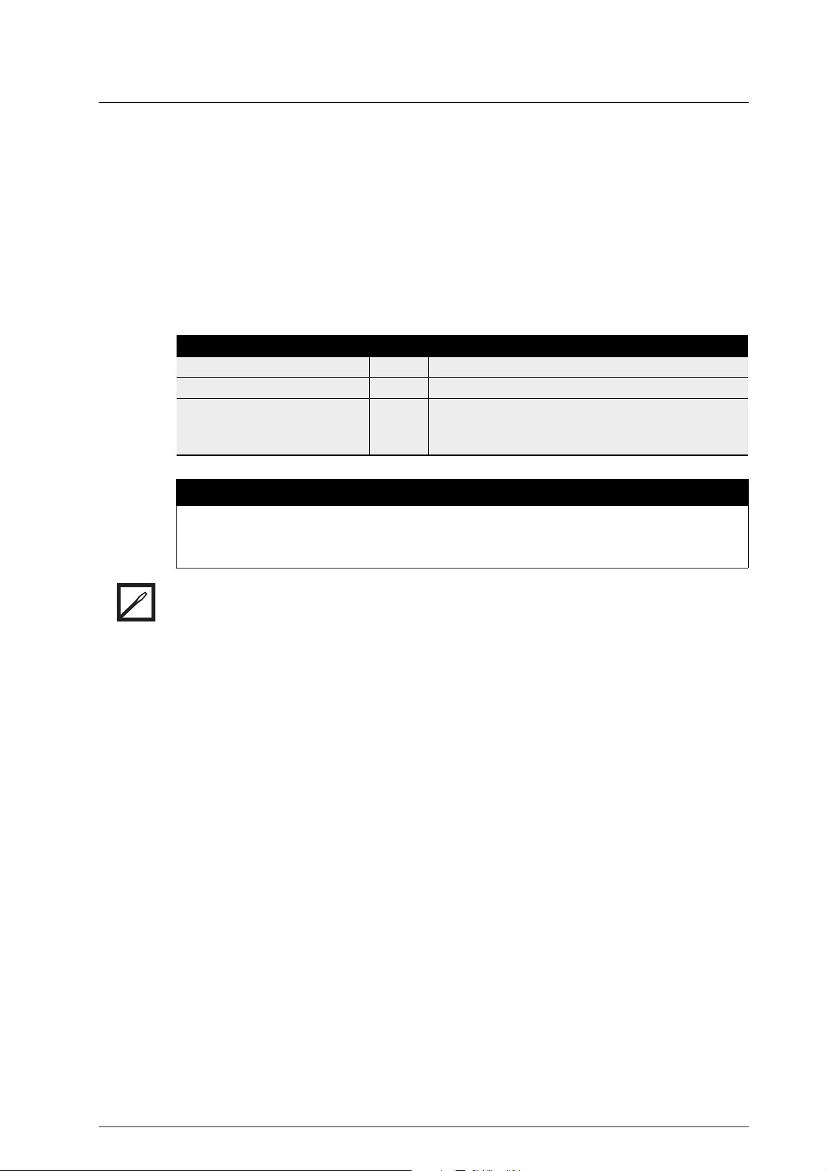
Target groups
Target group Tasks
Operator-owner □ Keep these instructions available at the system site for future
reference.
□ Ensure that employees read and observe these instructions and the
associated documents, in particular the safety instructions and
warnings.
□ Observe additional system-specific directives and regulations.
Specialist personnel, fitters □ Read, observe and follow these instructions and the associated
documents, in particular the safety instructions and warnings.
Symbols
Symbol Meaning
Warning personal injury
About this document
Notice
Procedures mechanical installation
Procedures electrical installation
Check or fault table
Request for action
Operating Instructions OIO 23en Edition 10/2017 3

Danger levels
Danger levels
Warning Danger level Consequences of non-observances
Danger Immediate threat of danger Serious personal injury, death
Warning Possible threat of danger Serious personal injury, invalidity
Caution Potentially dangerous situation Slight personal injury
About this document
Caution Potentially dangerous situation Material damage
Associated documents
Calibration certificate
Declaration of conformity according to EU Directive 2006/42/EC
Declaration of conformity according to EU Directive 2014/34/EU
ATEX supplementary instructions for operation in potentially explosive areas
Manufacturer's declaration according to EU Directive 2014/68/EU
Corresponding operating instructions for pick up
Corresponding operating instructions for electronic equipment
4 OIO 23en Edition 10/2017 Operating Instructions

Proper use
Safety
Proper use
□ Use flowmeters of the OMP series solely for flow measurement of lubricating liquids that are
chemically neutral and do not contain any gas or solids content.
Safety
□ Flowmeters require the operation with clean liquids. If coarse soiling, solid particles in the liquid or
abrasive fine particles occur during operation, the flowmeter has to be protected additionally by a
correspondingly dimensioned operating filter in the pipe system, see "Cleaning the pipe system",
page 27.
□ Only use flowmeters within the operational limits specified on the rating plate and in the "Technical
data" section. Deviating operating data can result in damage to the flowmeter. In the case of
operating data that does not agree with the specifications on the rating plate, please contact the
manufacturer.
□ Strong changes to the flow rate (e.g. rapid shutdown, pulsations ...) cause marked pressure
differences on the flowmeter and can damage the measuring unit.
▪ The pressure loss of the flowmeter must not exceed the values given in the chapter "Technical
data", see "Load-bearing capacity", page 14.
Safety information
The following safety instructions must be observed:
□ No liability is accepted for damage arising through non-observance of the operating
instructions.
▪ Read the operating instructions carefully and observe them.
▪ The operator-owner is responsible for the observance of the operating instructions.
▪ Installation, removal and installation work may only be carried out by specialist personnel.
□ Flowmeters wear to different degrees depending on the respective operating conditions
(pulsations, temperature, …).
▪ Do not continue to use flowmeters that are operated contrary to specifications or after damage.
▪ Check the flowmeters regularly.
▪ Shut down damaged flowmeters and replace worn flowmeters immediately.
□ In order for the warranty to remain valid, corrective maintenance carried out during the
warranty period requires the express permission of the manufacturer.
□ Observe the general regulations for the prevention of accidents as well as the local safety
and operating instructions.
□ Observe the valid national and international standards and specifications of the installation
location.
□ In case of systems with an increased potential of danger to humans and/or machines the
failure of a flowmeter may not lead to injuries or damage to property.
▪ Always equip systems with an increased potential of danger with alarm equipment and/or
bypass.
▪ Maintain and check the protective/alarm equipment regularly.
□ The pumped liquids can be dangerous (e.g. hot, dangerous to health, poisonous,
combustible). Observe the safety conditions for handling dangerous materials.
□ Pumped liquids can be subject to pressure and can cause damage and/or personal injury
should leaks occur.
Operating Instructions OIO 23en Edition 10/2017 5

Type code
OMP-020.FDBAAD.0001
Identification
Type code
Identification
Fig. 1 Type code
Item Designation Description
1 Series OMP: Universal
2 Size Corresponds to the diameter of the measuring screw large in [mm]
3 Sensor technology F: BEG 47
4 Function of sensor
5 Material of bearing B: Hybrid
6 Material of seal A: FPM (FKM)
7 Mechanical
8 Electrical
9 Version index For internal administration
1
technology
connection
connection
1 Series
68
2
4
3
5
I: BEG 56
K: BEG 64
X: Special design
A: Without flow direction detection
B: With flow direction detection
C: Without flow direction detection, with temperature compensation
D: With flow direction detection, with temperature compensation
X: Special design
B: FFPM
C: Low temperature FPM
D: EPDM
X: Special design
A: Pipe thread connection BSPP
B: Flange connection DIN
C: Pipe thread connection NPT
D: Flange connection ANSI
E: Flange connection JIS
X: Special design
A: Loose cable head
B: Cable gland junction box
D: Mounting kit for electronic unit
X: Special design
7
9
2 Size
3 Sensor technology
4 Function of sensor technology
5 Material of bearing
6 Material of seal
7 Mechanical connection
8 Electrical connection
9 Version index
6 OIO 23en Edition 10/2017 Operating Instructions

Rating plate
R
1
2
3
4
5
6
7
Rating plate
Fig. 2 Rating plate
1 Serial number
2 Year of construction
3 K-factor
4 Preferred flow direction
5 Maximum temperature
6 Type
7 Maximum pressure
Identification
Operating Instructions OIO 23en Edition 10/2017 7
Operating limits
10 3020 40 t [ms]
30
10
20
0
p
[bar]
Technical data
Operating limits
The values specified on the rating plate and the calibration certificate apply. The permissible operational
limits of individual values influence each other so that every application is checked individually by the
manufacturer when selecting the flowmeter.
If no operating data are provided by the orderer, standardized substitute operating data are used.
Technical data
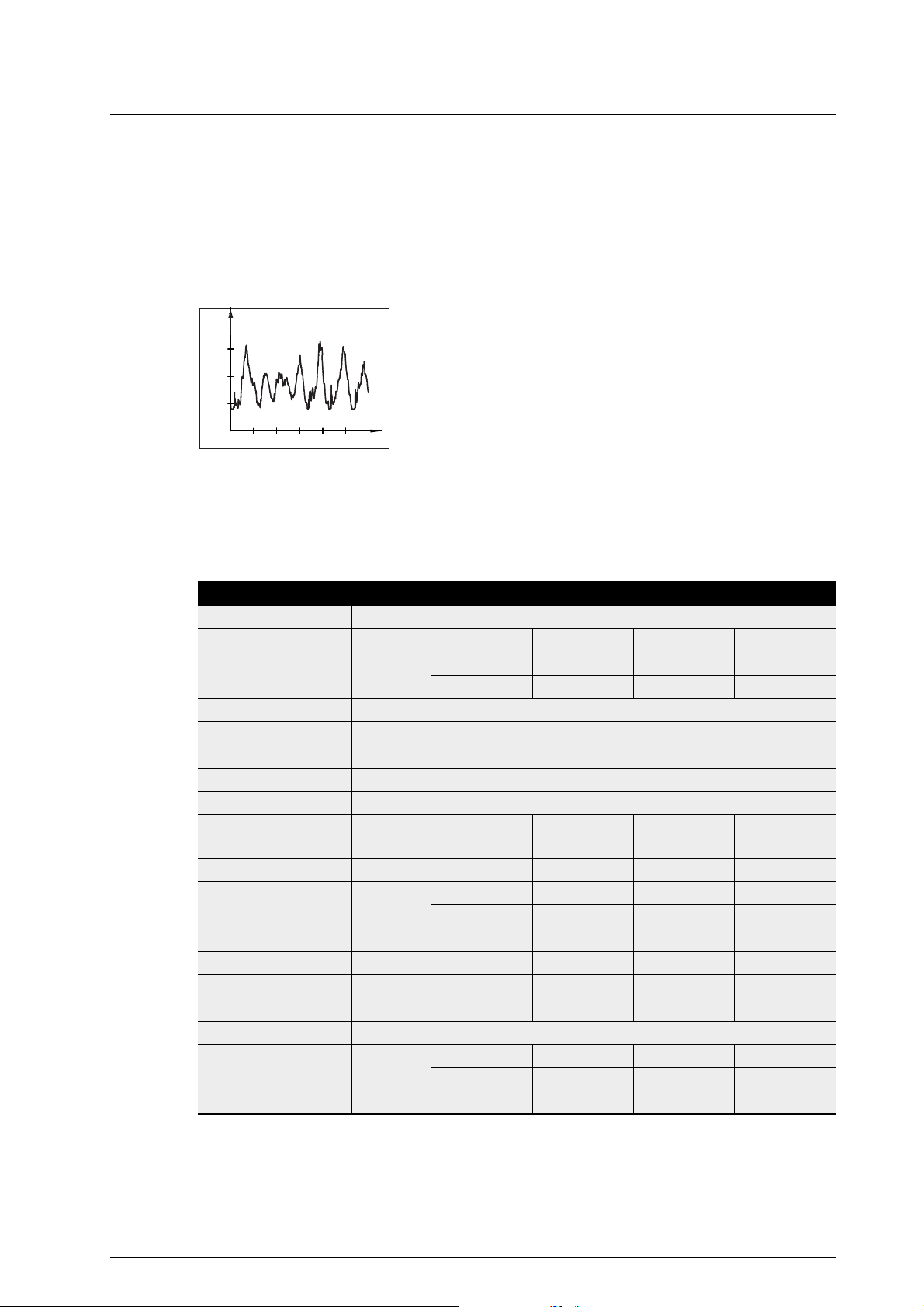
Load due to pressure pulsation
Fig. 1 Pressure pulses
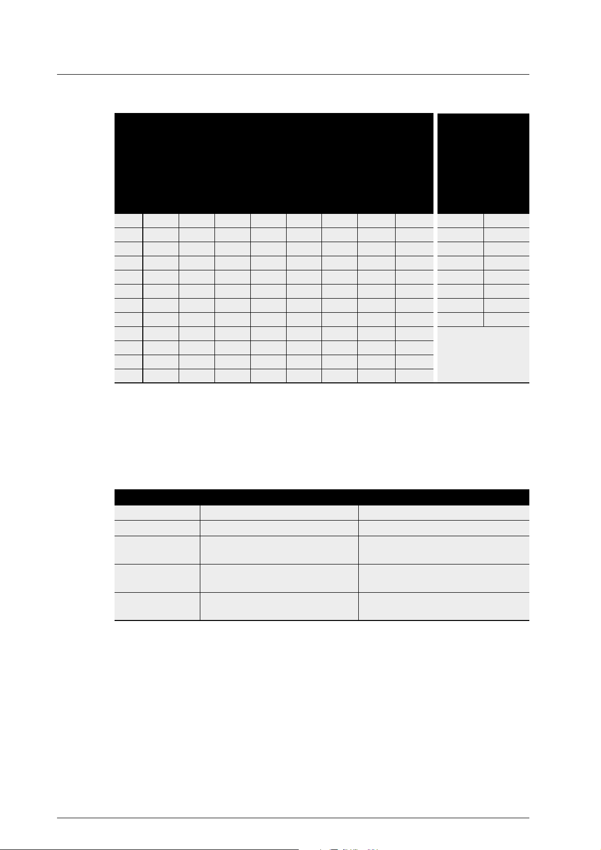
Maximum values
The following table shows the respective maximum values that, however, may not occur simultaneously.
In addition, the operational limits of the corresponding completion, of the sealing material and of the pick
up are to be observed.
Strong pressure pulses in the system can reduce the lifetime of
the flowmeter.
Unit OMP 13 OMP 20 OMP 32 OMP 52
Flow rate
Q
max
Q
nom
Q
min
[l/min] 15 45 150 525
10 30 100 350
0,1 0.3 1.0 3.5
Max. pressure [bar] 40
Temperature
min. – max. [°C] -20...+200
Viscosity
min. – max. [mm2/s] 1 – 1 000000
Measuring chamber
volume
[ml/U] 1,65 6.25 25.6 112.7
Rotation speed
n (Q
n (Q
n (Q
) [min-1] 9120 7200 5850 4658
max
) 6060 4 800 3900 3105
nom
) 61 48 39 31
min
Pole number 2 2 2 2
K-factor [P/l] 1214 321.0 78.0 17.73
Milliliters/pulse [ml/P] 0,824 3.12 12.8 56.4
Pulse frequency
f1 (Q
f1 (Q
f1 (Q
) [Hz] 304 242 195 155
max
) 202 161 130 104
nom
) 2,0 1.6 1.3 1.0
min
Tab. 1 Maximum values
8 OIO 23en Edition 10/2017 Operating Instructions

Sound pressure level
5
1
2
1
4
3
6
7
X
Substitute operating data
The following table shows standardized values for the flow rate, temperature and viscosity. These
values can be used at the same time as maximum values without impairing the service life of the
flowmeter. In addition, the operational limits of the corresponding completion, of the sealing material of
the pick up and of the temperature sensor are to be observed.
Unit OMP 13 OMP 20 OMP 32 OMP 52
Flow rate
Q
max
Q
nom
Q
min
Max. pressure [bar] 40
Temperature
min. – max. [°C] -20...+125
Viscosity
min. – max. [mm2/s] 1–200
Tab. 2 Substitute operating data
[l/min] 10 30 100 350
10 30 100 350
0,2 0.6 2.0 7.0
Sound pressure level
The sound pressure level of the flowmeter amounts to less than 70 dB(A).
Heating system
A heating system is not installed at the factory. The customer can optionally fit OMP-series KRAL
flowmeters with a trace heating system. The manufacturer recommends heating systems for highviscosity liquids that do not flow sufficiently if not heated, because bearing damage and destruction of
the device may otherwise result.
Technical data
Trace heating system
Contact the manufacturer before installing a trace heating system.
4
Fig. 2 Flowmeter with trace heating system
Operating Instructions OIO 23en Edition 10/2017 9
1 Heat insulation
2 Trace heating
3 Pick up with
connecting cable
4 Piping
5 Temperature sensor
with connecting cable
6 Junction box
7 Flowmeter
X Area stringently without
heat insulation
Dimensions and weights
G
T T
G1/4"
M16x1 /
M18x1
L2 L3
L1
L4
D
CAUTION
Defective pick up, temperature sensor or cabling due to exceeding of the maximum temperature.
► Do not heat the pick up, temperature sensor, junction box and corresponding cables above the
temperature specified in the associated operating instructions.
Technical data
► Ensure that pick up 3, temperature sensor 5, junction box 6 and corresponding cables are not heat
insulated. The area X has to be free of heat insulation, see Fig. 2, page 9.
Dimensions and weights
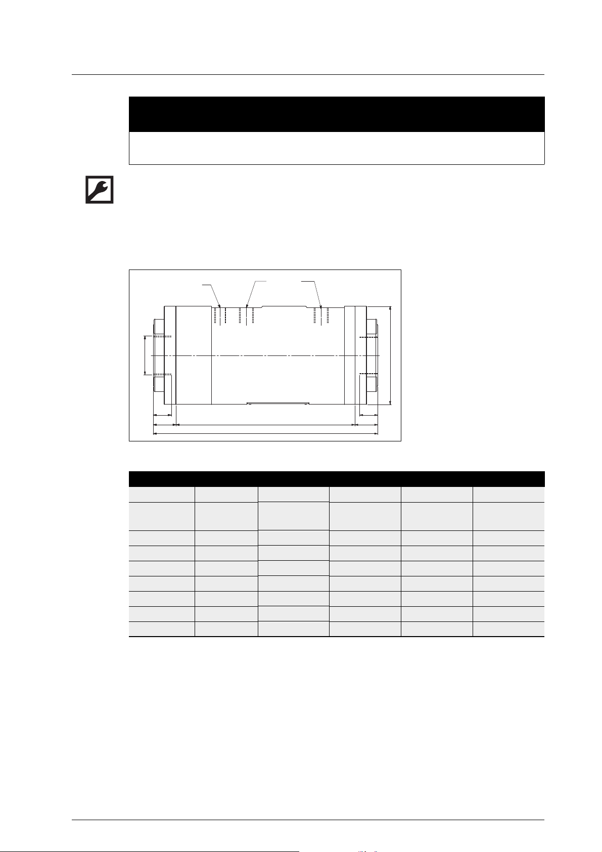
OMP with pipe thread (BSPP thread)
Fig. 3 Dimensional drawing OMP with pipe thread
G
M16x1/
M18x1
G1/4"
D
L1
L2
L3, L4
T
Pipe thread
Pick up hole/
Mounting connection
element
Temperature sensor
hole
Outer diameter
Total length
Flowmeter length
without connections
Flange thickness
Max. screw-in depth
Unit OMP 13 OMP 20 OMP 32 OMP 52
G [inch] 1/2 3/4 1 1 1/2
Pressure
stage
D [mm] 90 74 104 118
L1 [mm] 115 145 215 270
L2 [mm] 64 85 140 215
L3 [mm] 25,5 38.0 47.0 27.5
L4 [mm] 25,5 22.0 28.0 27.5
T [mm] 15 16 18 22
Weight [kg] 3,4 3.5 11.0 18.0
Tab. 3 Dimensions and weights – Pipe thread connection
[bar] 40 40 40 40
10 OIO 23en Edition 10/2017 Operating Instructions
Dimensions and weights
DN
G1/4"
M16x1 /
M18x1
L2
L4
L1
Tk
L3
D
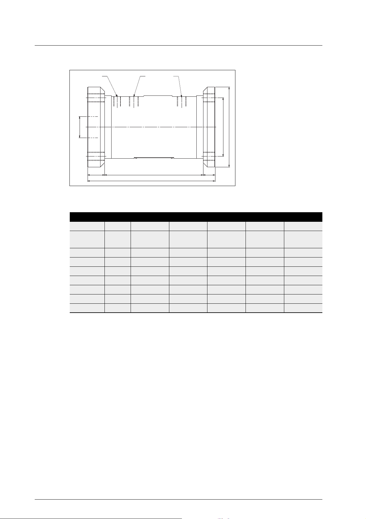
OMP with DIN flange
DN
M16x1/
M18x1
G1/4"
D
L1
L2
L3, L4
TK
Fig. 4 Dimensional drawing OMP with DIN flange
Unit OMP 13 OMP 20 OMP 32 OMP 32 OMP 52
DN 15 20 25 32 40
Pressure
stage
D [mm] 95 105 115 140 150
L1 [mm] 115 125 180 190 240
L2 [mm] 64 85.0 140.0 140.0 185.5
L3 [mm] 25,5 20 20 25 32
L4 [mm] 25,5 20.0 20.0 25.0 22.5
TK [mm] 65 75 85 100 110
Weight [kg] 3,7 5.0 11.2 13,5 19.2
[bar] 40 40 40 40 40
Nominal diameter
flange
Pick up hole/
Mounting connection
element
Temperature sensor
hole
Outer diameter
Total length
Flowmeter length
without connections
Flange thickness
Pitch circle
Technical data
Tab. 4 Dimensions and weights – DIN flange connection
Operating Instructions OIO 23en Edition 10/2017 11
Dimensions and weights
DN
G1/4"
M16x1 /
M18x1
L4
L1
L3
TK
DN
L2
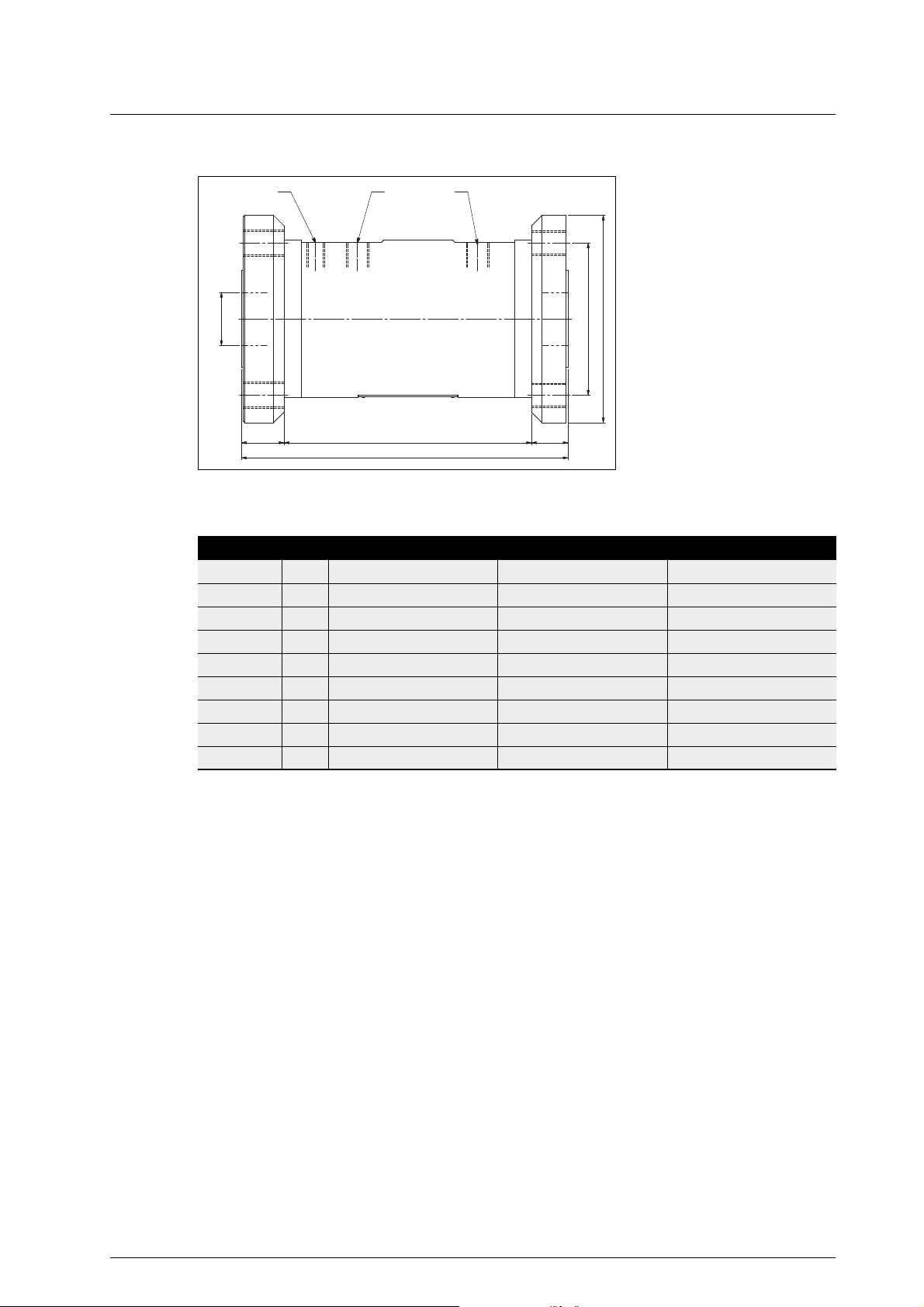
OMP with ANSI flange
Technical data
Fig. 5 Dimensional drawing OMP with ANSI flange
DN [inch] 3/4 1 1 1/2
Class 300 300 300
D [mm] 117.5 123.8 155.6
L1 [mm] 134 195 245
L2 [mm] 85.0 140.0 185.5
L3 [mm] 24.5 27.5 32.0
L4 [mm] 24.5 27.5 27.5
TK [mm] 82.5 88.9 114.3
Weight [kg] 6.0 12.5 19.6
DN
M16x1/
M18x1
G1/4"
D
L1
L2
L3, L4
TK
Unit OMP 20 OMP 32 OMP 52
Nominal diameter
flange
Pick up hole/
Mounting connection
element
Temperature sensor
hole
Outer diameter
Total length
Flowmeter length
without connections
Flange thickness
Pitch circle
Tab. 5 Dimensions and weights – ANSI flange connection
12 OIO 23en Edition 10/2017 Operating Instructions

Dimensions and weights
DN
G1/4"
M16x1 /
M18x1
L2 L4
TK
D
L3
L1
OMP with JIS flange
DN
M16x1/
M18x1
G1/4"
D
L1
L2
L3, L4
TK
Fig. 6 Dimensional drawing OMP with JIS flange
Unit OMP 20 OMP 32 OMP 52
DN 20 25 40
Pressure
stage
D [mm] 100 125 140
L1 [mm] 125 190 260
L2 [mm] 85 140 215
L3 [mm] 20.0 25.0 22.5
L4 [mm] 20.0 25.0 22.5
TK [mm] 75 90 105
Weight [kg] 4.5 12.2 19.0
16K 16K 16K
Nominal diameter
flange
Pick up hole/
Mounting connection
element
Temperature sensor
hole
Outer diameter
Total length
Flowmeter length
without connections
Flange thickness
Pitch circle
Technical data
Tab. 6 Dimensions and weights – JIS flange connection
Operating Instructions OIO 23en Edition 10/2017 13

Load-bearing capacity
20
18
16
14
12
2
4
6
8
10
0
A
B
1000 h
30000 h
10000 h
5000 h
100000
5
10
50
200
500
1000
2000
5000
10000
50000
100
[mm
2
/s]
C
[bar]
[bar]
C
2
3
0
1
100000
5000
10000
50000
5
10
50
200
500
1000
2000
100
[mm
2
/s]
2
34
109
8
7
65
0,1
1
15
14
13
12
11
E
D
[l/min]
100 50
150
D
[l/min]
50
45
40
30
25
20
1510
51
35
3,5 2,5
1,50,5
0,1
4,5
5
1 2 3
4
[%]
[%]
1
Load-bearing capacity
Load-bearing capacity OMP 13
Technical data
A Short-time operation
14 OIO 23en Edition 10/2017 Operating Instructions
B Continuous operation
C Pressure loss
D Flow rate
E Q
nom
The values apply for lubricating liquids at temperatures of up to 120 °C. Abrasive and aggressive liquids
reduce the durability.

Load-bearing capacity
20
18
16
14
12
2
4
6
8
10
0
A
B
1000 h
30000 h
10000 h
5000 h
100000
5
10
50
200
500
1000
2000
5000
10000
50000
100
[mm
2
/s]
C
[bar]
[bar]
C
2
3
0
1
100000
5000
10000
50000
5
10
50
200
500
1000
2000
100
[mm
2
/s]
6
912
3027
24
21
1815
0,3
3
45
42
39
36
33
E
D
[l/min]
100 50
150
D
[l/min]
50
45
40
30
25
20
1510
51
35
10,5 7,5
4,51,5
0,3
13,5
15
3 6 9
12
[%]
[%]
1
Load-bearing capacity OMP 20
Technical data
A Short-time operation
B Continuous operation
C Pressure loss
D Flow rate
E Q
nom
The values apply for lubricating liquids at temperatures of up to 120 °C. Abrasive and aggressive liquids
reduce the durability.
Operating Instructions OIO 23en Edition 10/2017 15

Load-bearing capacity
Load-bearing capacity OMP 32
Technical data
C
[bar]
D
20
18
16
14
12
10
8
6
4
2
0
[l/min]
[%]
100000
50000
1
1
2
/s]
1000 h
5000 h
10000 h
30000 h
140
150
150
[mm
1000
500
200
100
50
10
5
20
5000
30 40
6050
10000
B
10
2000
A
E
70
80
10090
100 50
110
120
130
100000
50000
10000
5000
3
2
C
1
[bar]
0
D
[l/min]
[%]
1
51
2000
10 20 30
155
1510
20
25
1000
40
35 25
30
35
45
40
45
2
[mm
/s]
500
200
100
50
10
5
50
50
A Short-time operation
B Continuous operation
C Pressure loss
D Flow rate
E Q
nom
The values apply for lubricating liquids at temperatures of up to 120 °C. Abrasive and aggressive liquids
reduce the durability.
16 OIO 23en Edition 10/2017 Operating Instructions

Load-bearing capacity
20
18
16
14
12
2
4
6
8
10
0
A
B
1000 h
30000 h
10000 h
5000 h
100000
5
10
50
200
500
1000
2000
5000
10000
50000
100
[mm
2
/s]
C
[bar]
[bar]
C
2
3
0
1
100000
5000
10000
50000
5
10
50
200
500
1000
2000
100
[mm
2
/s]
70
105 140
350315
280
245
210175
3,5
35
525
490
455
420
385
E
D
[l/min]
100 50
150
D
[l/min]
50
45
40
30
25
20
1510
51
35
122,5 87,5
52,517,5
3,5
157,5
175
35 70 105
140
[%]
[%]
1
Load-bearing capacity OMP 52
Technical data
A Short-time operation
B Continuous operation
C Pressure loss
D Flow rate
E Q
nom
The values apply for lubricating liquids at temperatures of up to 120 °C. Abrasive and aggressive liquids
reduce the durability.
Operating Instructions OIO 23en Edition 10/2017 17

Description
41 6 4 1
89
7
2*
2*3
5
Function description
Description
Function description
Fig. 1 Structure, flowmeter OMP series
1 Connection
2* Bearing cover
3 Temperature sensor hole
4 Pick up hole
5 Measuring housing
* only for OMP 52
As screw meters flowmeters belong to the group of rotating displacement meters. The fluid current
makes the measuring unit rotate. The displacement effect results from the continuous filling, axial
displacement and discharge of the volumes that are formed by the measuring housing and measuring
unit. The measured liquid flows around and lubricates all the rotating parts. Thanks to the displacement
principle, the flowmeter does not require inlet and smoothing sections in its supply and discharge.
Depending on the customer requirements, the flowmeters can be equipped with suitable end
connections for connection to various flanges.
6 Measuring screw small
7 Ball bearing, floating bearing end
8 Measuring screw large
9 Ball bearing, fixed bearing end
Rolling bearings
The measuring unit is maintained without contact and with a low degree of friction in the housing of the
flowmeter by means of precision rolling bearings. Depending on the respective size, the following
bearings are used:
□ Single-row deep-groove ball bearings
□ Paired angular-contact ball bearings
18 OIO 23en Edition 10/2017 Operating Instructions

Signal generation
Signal generation
A pick up samples the measuring pulses directly on the screw. The pick up generates a specific number
of pulses per flow volume unit – depending on the size and working point. This device-specific
characteristic is called the K-factor (unit: Pulse/Liter) and can be found on the rating plate and the
enclosed calibration certificate. Possible formats of the signals are:
□ PNP
□ NAMUR
The mounting method of the pick-up allows mounting without contact to the fluid to be measured. Two
different pick ups are employed, depending on the application (standard, or for use in areas where there
is an explosion hazard):
□ Pick up based on the Hall effect
□ Inductive pick up
Linearization
The calibration certificate contains a mean K-factor that has been determined for the flow range 10:1
and that can therefore be used across a wide flow range. However, the K-factor shows slightly different
values at different flow rates. These are also documented in the enclosed calibration certificate. If
highest measuring precision is required, it is therefore advisable, especially at strongly varying flow
rates, to take these different values into consideration by means of a "Linearization". The K-factors are
therefore fed into a suitable electronics unit across several interpolation values of the flow rate. The Kfactor relevant for the flow rate being measured is then determined by means of linear interpolation
between the two nearest interpolation values.
The viscosity dependence of the K-factors must also be taken into account. These are determined
during calibration at a viscosity of approximately 4.2 mm²/s. The influence of the flow rate on the K-factor
decreases at higher viscosities so that the mean K-factor can then also be used in a considerably larger
flow range without noteworthy errors.
Function description
Temperature compensation
If the flowmeter is additionally equipped with a temperature sensor, the current density of the flowing
liquid can be calculated from this measured value by means of a density table stored in the flow
management unit. A normalized volume measurement is then possible at which the displayed values
are converted to a reference temperature that can be selected freely. This ensures that measuring
errors caused by changes in the density due to temperature variations are avoided.
Flow direction detection
Systems with a changing flow direction as well as systems with pressure pulsations - that can also
cause a reversal of the flow direction - require the use of a second pick up. This additional signal (90°
phase-offset) and the incremental encoding inputs available in the KRAL electronic unit can be used to
determine the direction of flow and to take it into consideration when calculating the total values.
Junction box
The manufacturer offers a junction box that facilitates the electrical connection of the various sensors for
the flowmeters of the OMP series. For further information see "Accessories", page 42.
Operating Instructions OIO 23en Edition 10/2017 19

Unpacking and checking the state of delivery
Transportation, storage and dispos al
Unpacking and checking the state of delivery
1. Upon delivery unpack the flowmeter and check for transport damage.
2. Report damage during transportation immediately to the manufacturer.
3. Store the supplied pick up and temperature sensor for the installation.
4. Dispose of packing material in accordance with the locally applicable regulations.
Lifting the flowmeter
WARNING
Risk of injury and/or damage to equipment should the flowmeter fall.
► Use intact and correctly dimensioned hoisting equipment in accordance with the total weight to be
transported.
► Select the attachment points for the hoisting equipment in accordance with the center of gravity
and the weight distribution.
► Use at least two load ropes.
► Do not stand under raised loads.
Storage
As a result of the calibration, the internal components of the flowmeter are wetted with calibration liquid
Transportation, storage and disposal
that has a preservative effect. In addition, a special anticorrosive agent is sprayed onto the interior of the
flowmeters before being dispatched. The connections of the flowmeter are fitted with protective caps.
Unless otherwise specified, the external components of the flowmeter are preserved with a single-coat
PU-based two-component paint. The preservation applied at the factory will protect the flowmeter for up
to six weeks, if it is stored in a dry and clean location. The manufacturer offers a long-term preservation
for storage times of up to 60 months. The flowmeter is additionally packed in hermetically sealing anticorrosion paper.
CAUTION
Damage to device through corrosion if stored improperly and during longer standstills.
► Protect the flowmeters against corrosion during long standstills.
► Observe the chapters "Storage" and "Preservation".
Preservation
Preservation has to be carried out additionally under the following conditions:
Type of delivery Condition
Standard delivery
□ Storage time exceeding six weeks
□ Unfavorable storage conditions such as high
humidity, salty air, etc.
Delivery with long-term preservation
Tab. 1 Check table for preservation
Preserving the flowmeter
1. Close a connection of the flowmeter with a blind flange.
2. Position the flowmeter vertically.
3. Fill non-corrosive and resin-free oil up to approx. 1 cm under the connection at the top, while turning
the measuring unit slowly, so that the measuring unit also comes into contact with it.
4. Close the upper connection with a blind flange.
5. Apply non-corrosive and resin-free oil to all the plain and unpainted parts of the outer housing.
□ Opened or damaged packaging
20 OIO 23en Edition 10/2017 Operating Instructions

Disposal
After about six months storage check the oil level in the flowmeter and if necessary top up oil. Check the
preservation of the outer housing and if necessary apply oil to the parts again.
Notice:
Store the preserved flowmeter cool and dry and protect it against direct sunlight.
Notice:
After a longer storage time the manufacturer recommends that you have the flowmeter recalibrated, see
"Re-calibration of the flowmeters", page 29.
Removing the preservation
Aids:
□ Solvents suitable for the preservative oil
□ Vessel to collect the preservative oil
WARNING
Risk of injury through emitted preservative oil.
► Wear protective clothing during all the work.
► Open the blind flange carefully in order to reduce any pressure that may exist in the flowmeter.
► Collect the emitted preservative oil safely and dispose of it in an environmentally compatible
manner.
Transportation, storage and disposal
1. Remove one of the blind flanges.
2. Drain the flowmeter, collecting the preservative oil in a suitable vessel.
3. Remove the second blind flange.
4. Use a solvent to remove the residual oil.
- or -
► Rinse the flowmeter with pumped liquid.
Disposal
Aids:
□ Solvents or industrial cleaners suitable for the pumped liquid
WARNING
Danger of poisoning and environmental damage from the pumped liquid.
► Wear protective clothing during all the work.
► Before disposing of the flowmeter collect the discharging pumped liquid and dispose of in
accordance with the locally applicable regulations.
► Before disposing of the flowmeter neutralize the residues of the pumped liquid in the flowmeter.
1. Disassemble the flowmeter.
2. Clean residues of the pumped liquid from the individual parts.
3. Separate sealing elements made of elastomer from the flowmeter and dispose of them in the
residual waste.
4. Recycle cast-iron and steel parts.
Operating Instructions OIO 23en Edition 10/2017 21

Safety instructions for installation and removal
1
2
3
4
Installation, removal and connection
Safety instructions for installation and removal
The following safety instructions must be observed:
□ Flowmeters are precision measuring devices.
► Ensure cleanliness and take care during installation and removal.
► Do not take apart the flowmeter.
► Do not remove the protective caps from the dry sleeves during installation. Put the protective
caps on the dry sleeves during removal.
► During installation only remove the screw plugs in order to insert the temperature sensor. Screw
in the screw plugs again after the temperature sensor has been removed.
► If installing a trace heating system, pick up, temperature sensor, junction box and corresponding
cables have to be free of heat insulation, see "Trace heating system", page 9.
Installing the flowmeter
Flowmeters of the OMP series can be operated in any mounting position.
Notice:
Both directions of flow are possible. The preferred flow direction is indicated on the rating plate by
means of a bright arrow, see Fig. 2, page 7.
Installation, removal and connection
Installation types
Fig. 1 OMP installation types
The arrow with dashed line identifies the preferred flow direction when an operating filter is used.
Installation type Properties
1 □ Without bypass
□ With or without operating filter
2 □ Manual bypass
□ With or without operating filter
3 □ Bypass with 3 stop valves for flange
connection
□ Small space requirements
□ Dismantling of the flowmeter only with
interruption of operation
□ Bypass is opened manually
□ Dismantling of the flowmeter only with
interruption of operation
□ Dismantling of the flowmeter without
interruption of operation
□ With or without operating filter
4 □ Bypass with 3 stop valves for pipe thread
connection
□ With or without operating filter
Tab. 1 OMP installation types
22 OIO 23en Edition 10/2017 Operating Instructions
□ Dismantling of the flowmeter without
interruption of operation
□ Minimally higher pressure loss

Installing the flowmeter
9
X
X
X
X
Preferred installation variant
Recommendations for alternative installation variants
Flow vertically from bottom to top
► Preferred installation variant.
Flow vertically from top to bottom
► Ensure that the liquid does not flow freely out
of the flowmeter, for example by routing the
piping upwards.
9
Horizontal flow
► Ensure that the liquid does not flow freely out
of the flowmeter, for example by routing the
piping upwards.
Installation, removal and connection
No vertical installation with open outlet
► Measuring error through free flowing of the
liquid out of the flowmeter.
X
No horizontal installation at the highest
point in the pipe system
► Avoid measuring error through formation of
an air pocket in the flowmeter.
No air bubbles in the pipe system
► Measuring error through air bubbles in the
pipe system. Vent the complete pipe system
thoroughly during commissioning.
Operating Instructions OIO 23en Edition 10/2017 23

Installing the flowmeter
CAUTION
Measuring error through air in the pipe system and/or incorrect installation of the flowmeter.
► In the case of horizontal installation of the flowmeter at the highest point of the pipe system an air
pocket can arise that results in measuring errors.
► Vent the pipe system thoroughly before commissioning.
► At a vertical installation of the flowmeter and the flow direction from top to bottom ensure that the
liquid does not flow freely out of the flowmeter, for example by routing the pipe upwards or by
reducing the pipe diameter with a reducer.
► During the installation of the flowmeter observe the recommendations for the installation variants
and avoid error sources, see "Installing the flowmeter", page 22.
Protect the flowmeter against soiling
Notice:
In order to protect the flowmeter against soiling the manufacturer generally recommends the installation
of an operating filter, mesh width see Tab. 1, page 27.
CAUTION
Installation, removal and connection
Damage to equipment through impurities in the pipe system.
► During welding work attach protective covers in front of the connecting flanges.
► Ensure when welding that welding beads and abrasive dust cannot get into the pipe system and
the flowmeter.
► After the connecting work clean the pipe system thoroughly, see "Cleaning the pipe system",
page 27.
Connecting the flowmeter to the pipe system
The connection of the flowmeter to the pipe system must be stress-free.
Fig. 2 Flange connections
CAUTION
Damage to equipment or impaired functionality through mechanical stresses.
► Ensure that the flowmeter mounting on the pipe system is free of mechanical stress.
CAUTION
Damage to device when the pipe threading is screwed in too far.
► Observe the thread length of the flowmeter.
► Use a standard cutting ring screwed connection.
24 OIO 23en Edition 10/2017 Operating Instructions

Electrical installation
1. Remove the protective covers and store them.
2. Install the flowmeter stress-free in the pipe system while taking the preferred direction of flow into
account and ensure that the connections of the pick up remain accessible.
3. The screw-in length of the piping may not exceed the threaded length of the flowmeter, since the
flow cross-section is narrowed and internal components can be damaged.
Electrical installation
Safety instructions for electrical installation
Observe the following safety instructions during the electrical installation:
□ The following qualifications are required for the electrical installation:
▪ Practical electrotechnical training
▪ Knowledge of the safety guidelines at the workplace
▪ Knowledge of the electrotechnical safety guidelines
► The connecting line of the connections for pick ups and temperature sensor are to be
shielded and laid separately from the supply lines.
► Ensure that the supply voltage is correct.
► Observe the operating instructions for pick up, temperature sensor and electronic equipment.
Installation, removal and connection
Connection for the pick ups
The flowmeter can be equipped with two pick ups for flow direction detection. The first signal measures
the flow rate, the second signal determines the direction of flow. The pick ups have to be connected
correctly in order to obtain the correct values. The connections are marked on the flowmeter housing
and "2". This marking depends on the preferred direction of flow in accordance with the arrow on
with "1"
the rating plate, see Fig. 2, page 7. In the case of a direction of flow contrary to the preferred direction of
flow the connections have to be swapped in order to obtain a correct signal.
CAUTION
Measuring error through incorrectly mounted pick ups.
► Ensure that the pick ups are mounted at the correct position.
► Observe the corresponding operating instructions for pick ups.
Removing the flowmeter
Prerequisite:
□ System switched off
Aids:
□ Vessel to collect pumped liquid
DANGER
Risk of death resulting from electric shock while the heating is being removed.
► Ensure that the supply voltage is de-energized.
► The flowmeter may only be separated from the power supply by an authorized electrician.
Operating Instructions OIO 23en Edition 10/2017 25
Removing the flowmeter
WARNING
Risk of injury through emitted hot, poisonous or corrosive pumped liquid when removing the
flowmeter.
► Observe the safety regulations for handling dangerous liquids.
► Ensure that the flowmeter is not under pressure.
► Collect the emitted pumped liquid safely and dispose of it in an environmentally compatible
manner.
1. In case of operation at higher temperatures wait until the device has cooled down to the ambient
temperature.
2. Drain the pipe system or divert the fuel via the bypass.
3. Dismantle the flowmeter.
4. Apply the protective cover.
5. Observe the chapters "Storage" and "Preservation" on the subject of storing the flowmeter.
Installation, removal and connection
26 OIO 23en Edition 10/2017 Operating Instructions

Commissioning
Operation
Commissioning
Cleaning the pipe system
To protect the flowmeter against soiling carefully clean the complete pipe system before commissioning.
Possibilities:
□ Rinsing via bypass
□ Rinsing with flowmeter
CAUTION
Damage to equipment through usage of an incorrect rinsing liquid.
► Under no circumstances may water or superheated steam be used to rinse the pipe system.
► Rinsing via bypass: Close the shut-off devices before and after the flowmeter.
- or ► Rinsing with flowmeter: An operating filter has to be installed before the flowmeter. Take the mesh
width of the filter into account, see Tab. 1, page 27.
The mesh width of the operating filter is relevant to the size of the flowmeter.
Flowmeter size Unit Max. mesh width
OMP 13, 20 [mm] 0.1
OMP 32, 52 [mm] 0.34
Operation
Tab. 1 Mesh width of the operating filter
Checking the function
Test Procedure
Installation ► Check the direction of flow of the flowmeter.
► Check the installation and mounting position of
the pick ups and of the temperature sensor.
► Check the pipe threading/flange and the
temperature sensors for leaks under operating
pressure.
Electrical installation ► Observe the operating instructions for pick ups,
temperature sensor and electronic equipment.
Power supply ► Observe the operating instructions for pick ups,
temperature sensor and electronic equipment.
Tab. 2 Function check table
Commissioning the flowmeter
Prerequisite:
□ Ambient conditions correspond to the operating data, see "Technical data", page 8
□ Flowmeter correctly installed into the pipe system, see "Installing the flowmeter", page 22
□ Flowmeter connection to the pipe system is free of mechanical stress
□ Pipe system is free of contamination
□ Pipe system vented
□ Shut-off devices in the supply and discharge lines opened
Operating Instructions OIO 23en Edition 10/2017 27
Switching off the flowmeter
Operation
CAUTION
Measuring error through gas inclusion in the pipe system.
► Before commissioning, make sure that the flowmeter is filled.
► Vent the pipe system.
CAUTION
Increased wear and/or blocking of the flowmeter due to solid particles or abrasive fine particles in the
liquid.
► Protect the flowmeter by a correspondingly dimensioned operating filter in the pipe system.
► Switch on the system.
The flowmeter measures when the pick up generates a signal.
Switching off the flowmeter
Safety instruction for switching off the flowmeter
Pay attention to the following when switching off the flowmeter:
□ Strong changes to the flow rate (e.g. rapid shutdown, pulsations ...) cause marked pressure
differences on the flowmeter and can damage the measuring unit.
▪ The pressure loss of the flowmeter must not exceed the values given in the chapter "Technical
data", see "Load-bearing capacity", page 14.
Switching off the flowmeter
When the flow through the flowmeter is stopped, the generation of the signal stops automatically. No
further measures are required to switch off.
Recommissioning the flowmeter
Prerequisite:
□ Requirements for commissioning are met, see "Commissioning", page 27
CAUTION
Damage to device through hard, gummy or crystallized liquid in the flowmeter.
► Before commissioning, ensure that there is no hard, gummy or crystallized liquid in the flowmeter.
1. Disassemble and clean the flowmeter before recommissioning.
2. Switch on the system.
Under the requirements mentioned above, the flowmeter is ready for operation at any time.
28 OIO 23en Edition 10/2017 Operating Instructions
Safety instructions on repairs
Maintenance
Safety instructions on repairs
The following safety instructions must be observed during all the repair work:
► All the work may only be carried out by authorized qualified personnel.
► Wear protective clothing during all the work.
► The replacement of the measuring unit consisting of screw set and rolling bearing may only be
carried out in the factory.
► The flowmeter has to be recalibrated after measuring unit or rolling bearing has been replaced.
► Observe the pick up operating instructions when replacing the pick up insert.
► Observe the corresponding operating instructions when replacing the temperature sensor
insert.
Required maintenance
Flowmeters are fundamentally maintenance-free. Under observance of the operating limits, see
"Technical data", page 8, no significant change in the characteristics could be established, even after
years of use in many cases. Conditions lying clearly above the nominal flow rate can, however, result
in excessive wear. In the case of liquids with higher abrasiveness (e.g. heavy oil with catalyst
residues, plastic components with fillers, etc.) strongly accelerated wear can occur in the flowmeter.
Notice:
In cases of doubt the manufacturer recommends already carrying out the first inspection of the
flowmeter after twelve weeks operation time.
Maintenance
Signs of progressive wear of individual flowmeter elements:
Finding Cause Elimination
Increased running noises Incipient damage to bearing Replace the bearing.
Leakage Damage to sealing Replace the seals or dry sleeve.
Measured values not
realistic
Tab. 1 Check table for required maintenance
1. Check the flowmeter visually and acoustically every four weeks.
2. Check for signs of wear as listed in the table above and eliminate the cause.
see "Troubleshooting", page 37 see "Troubleshooting", page 37
Re-calibration of the flowmeters
In order to maintain the high measuring precision of the flowmeter, the manufacturer recommends
carrying out the first re-calibration after about one year of operation. The results reveal any wear starting
on the measuring unit. The interval at which recalibration is actually required depends strongly on the
operating conditions of the device.
The manufacturer provides the factory calibration as standard. If higher requirements are placed on the
measuring instrument, an accredited calibration according to EN ISO/IEC 17025 is also possible.
Operating Instructions OIO 23en Edition 10/2017 29
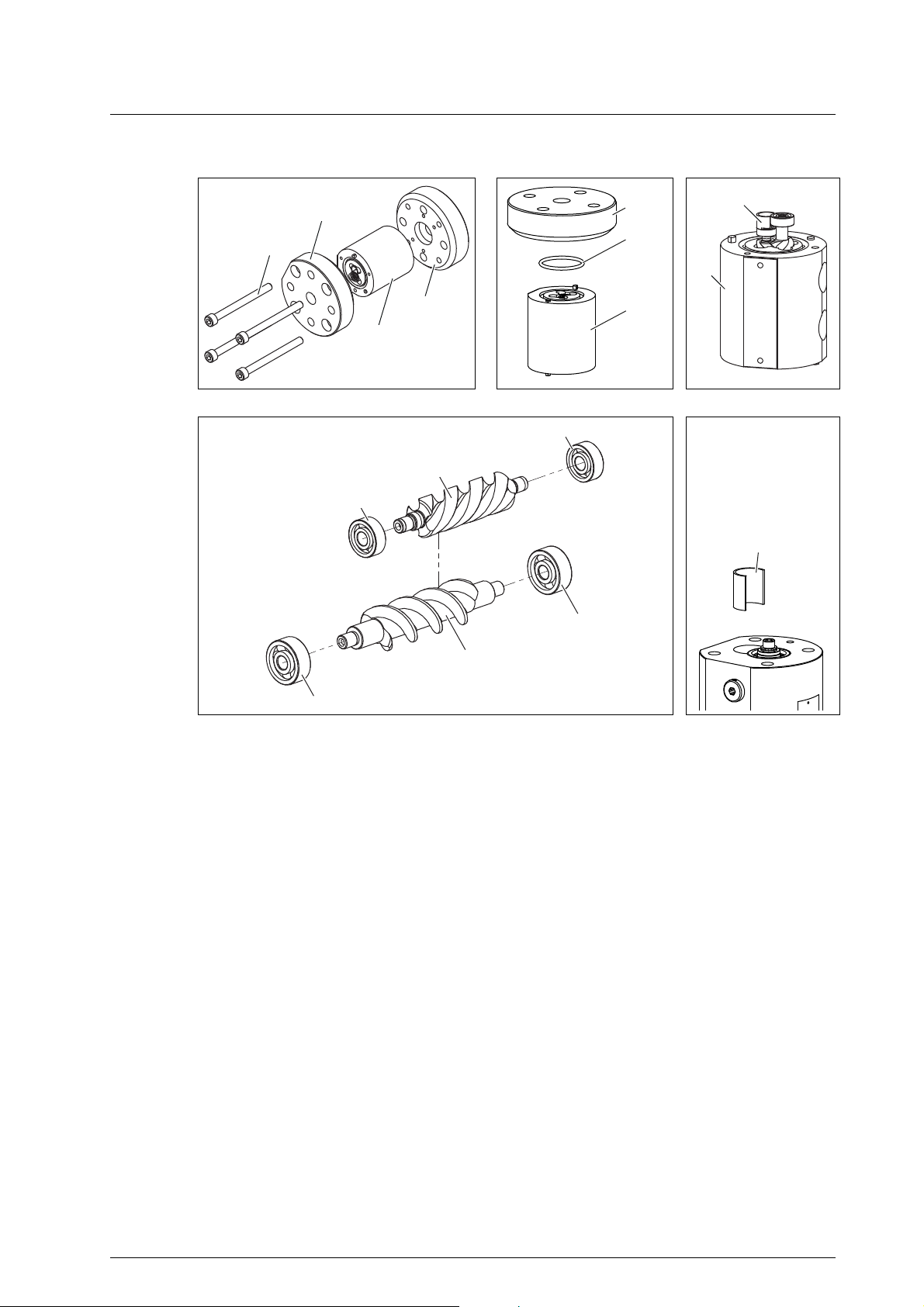
Mounting instructions OMP 13
915.5
115.1
128
115.2
128
817.3
817.4
672.2
817.1
672.1
817.2
039
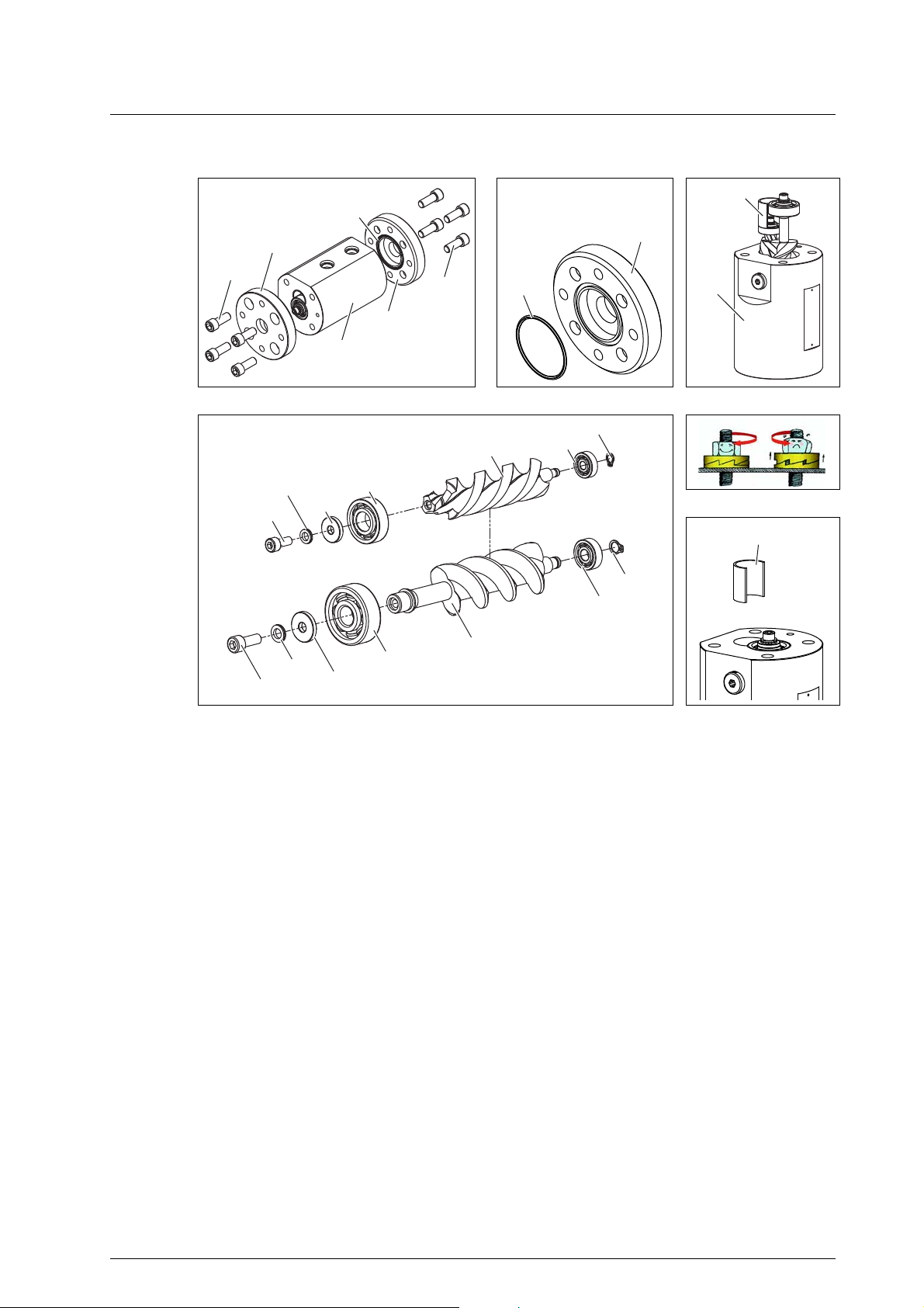
Mounting instructions OMP 13
Maintenance
Fig. 1 Fig. 2
115.1
739.1
039
128
Fig. 3
Fig. 4
039 Distance sleeve
115.1 Flange
115.2 Flange
128 Measuring housing
672.1 Measuring screw large
672.1 Measuring screw small
739.1 O-ring
739.2 O-ring
817.1 Deep-groove ball bearing
817.2 Deep-groove ball bearing
817.3 Deep-groove ball bearing
817.4 Deep-groove ball bearing
Fig. 5
915.5 Socket screw
30 OIO 23en Edition 10/2017 Operating Instructions

Mounting instructions OMP 13
Removing seals and bearings
Prerequisites:
□ Flowmeter removed from system
□ Pick up insert removed
1. Remove the socket screws 915.5 and the flanges 115.1 and 115.2, see Fig. 1, page 30.
2. Remove the O-rings 739.1 and 739.2, see Fig. 2, page 30.
3. Pull the distance sleeve 039 together with the set of screws out of the measuring housing 128, see
Fig. 3, page 30.
4. Pull the ball bearings 817.1, 817.2, 817.3 and 817.4 from the screws using the pulling-off device.
Installing seals and bearings
Prerequisites:
□ Replacement parts available
1. Place the O-rings 739.1 and 739.2 onto both sides of the measuring housing 128.
2. Press the ball bearings 817.1 and 817.2 onto the measuring screw large 672.1 and the ball bearings
817.3 and 817.4 onto the measuring screw small 672.2.
Notice: Press the ball bearings on only over the inner ring.
3. Place the flange 115.2 onto the measuring housing 128.
4. Slide the set of screws in the measuring housing 128. Slide the distance sleeve 039 into the hole of
the measuring screw small 672.2, see Fig. 5, page 30.
5. Place the flange 115.1 onto the measuring housing 128.
6. Pretension the oiled socket screws 915.5 crosswise and tighten with torque, see Tab. 6, page 47.
Maintenance
Operating Instructions OIO 23en Edition 10/2017 31
Mounting instructions OMP 20/32
915.1
115.1
128
115.2
915.2
739.2
739.1
128
915.7
904.2
064.2
817.3
869.4
817.4
672.2
915.6
064.1
904.1
817.1
672.1
817.2
869.2
039
Mounting instructions OMP 20/32
Maintenance
039
115.1
Fig. 6 Fig. 7
Fig. 10
039 Distance sleeve
064.1 Supporting ring
064.2 Supporting ring
115.1 Flange
115.2 Flange
128 Measuring housing
672.1 Measuring screw large
672.1 Measuring screw small
739.1 O-ring
739.2 O-ring
817.1 Deep-groove ball bearing
817.2 Deep-groove ball bearing
817.3 Deep-groove ball bearing
817.4 Deep-groove ball bearing
869.2 Circlip
869.4 Circlip
Fig. 8
Fig. 9
Fig. 11
904.1 Wedge lock washer
904.2 Wedge lock washer
915.1 Socket screw
915.2 Socket screw
915.6 Socket screw
915.7 Socket screw
32 OIO 23en Edition 10/2017 Operating Instructions

Mounting instructions OMP 20/32
Removing seals and bearings
Prerequisites:
□ Flowmeter removed from system
□ Pick up insert removed
1. Remove the socket screws 915.1 and 915.2, flanges 115.1 and 115.2, see Fig. 6, page 32.
2. Remove the O-rings 739.1 and 739.2, see Fig. 7, page 32.
3. Pull the distance sleeve 039 together with the set of screws out of the measuring housing 128, see
Fig. 8, page 32.
4. Remove the circlips 869.2 and 869.4 from the measuring screw large and measuring screw small.
Overview see Fig. 10, page 32.
5. Screw out the socket screws 915.6 and 915.7 and remove the wedge lock washers 904.1, 904.2 and
support rings 064.1, 064.2.
6. Pull the ball bearings 817.1, 817.2, 817.3 and 817.4 from the screws using the pulling-off device.
Installing seals and bearings
Prerequisites:
□ Replacement parts available
□ Loctite 242
1. Insert the O-rings 739.1 and 739.2 into the flange 115.1 and 115.2.
2. Press the ball bearings 817.1 and 817.2 onto the measuring screw large 672.1 and the ball bearings
817.3 and 817.4 onto the measuring screw small 672.2.
Notice: Press the ball bearings on only over the inner ring.
3. Pull the wedge lock washers 904.1 and 904.2 and support rings 064.1 and 064.2 onto the sockets
screws 915.6 and 915.7. Overview see Fig. 10, page 32.
Notice: Ensure that the wedge lock washers are positioned correctly (wedge surface to wedge
surface), see Fig. 9, page 32.
4. Mount the socket screws 915.6 and 915.7, with Loctite 242 applied, with mounted washer and ring
onto the measuring screw large and measuring screw small and tighten with torque, see Tab. 6,
page 47.
5. Mount the circlips 869.2 and 869.4 on the floating bearing end.
6. Place the flange 115.2 onto the measuring housing 128.
7. Pretension the oiled socket screws 915.2 crosswise and tighten with torque, see Tab. 6, page 47.
8. Slide the set of screws in the measuring housing 128. Slide the distance sleeve 039 into the hole of
the measuring screw small 672.2, see Fig. 11, page 32.
9. Place the flange 115.1 onto the measuring housing 128.
10. Pretension the oiled socket screws 915.1 crosswise and tighten with torque, see Tab. 6, page 47.
Maintenance
Operating Instructions OIO 23en Edition 10/2017 33

Mounting instructions OMP 52
115.1
115.2
915.1
915.2
739.1
739.2
080.1
915.3
739.3
128
739.4
080.2
915.4
739.3
080.1
128
915.6
904.1
064.1
915.7
904.2
064.2
080.1
057.2
057.1
080.1
904.2
915.7
064.2
818.2
868.4
817.2
057.2
672.2
869.4
672.1
817.1
868.2
869.2
904.1
064.1
915.6
818.1
057.1
054
Mounting instructions OMP 52
Maintenance
Fig. 12 Fig. 13
Fig. 14 Fig. 15 Fig. 16
Fig. 17
34 OIO 23en Edition 10/2017 Operating Instructions

Mounting instructions OMP 52
Fig. 18 Fig. 19
Maintenance
054
57.1
057.2
064.1
064.2
080.1
080.2
115.1
115.2
128
672.1
672.2
Removing seals and bearings
Prerequisites
Spacer
Threaded ring
Threaded ring
Supporting ring
Supporting ring
Bearing cover
Bearing cover (inlet)
Flange
Flange
Measuring housing
Measuring screw large
Measuring screw small
739.1
739.2
739.3
739.4
817.1
817.2
818.1
818.2
O-ring
O-ring (inlet)
O-ring
O-ring (inlet)
Deep-groove ball
bearing
Deep-groove ball
bearing
Angular-contact ball
bearing
Angular-contact ball
bearing
868.2
868.4
869.2
869.4
904.1
904.2
915.1
915.2
915.3
915.4
915.6
915.7
Support ring
Support ring
Circlip
Circlip
Wedge lock washers
Wedge lock washers
Socket screw
Socket screw
Socket screw
Socket screw
Socket screw
Socket screw
□ Flowmeter removed from the system
□ Completion consisting of socket screws 915.1/915.2, flanges 115.1/115.2 and seals 739.1/739.2
removed, overview see Fig. 12, page 34
□ Pick up inserts removed
1. Remove the socket screws 915.3 and 915.4, take off the bearing cover 080.2. Remove the O-ring
739.4, overview see Fig. 12, page 34.
2. Use light blows of a plastic tip hammer to drive the screw set together with the bearing cover 080.1
out of the measuring housing 128 and pull out, see Fig. 13, page 34.
3. Screw out the socket screw 915.6 with wedge lock washer 904.1 and supporting ring 064.1 from the
measuring screw large 672.1, see Fig. 14, page 34.
4. Screw out the socket screw 915.7 with wedge lock washer 904.2 and supporting ring 064.2 from the
measuring screw small 672.2, see Fig. 14, page 34.
5. Remove the screw set from the bearing cover 080.1 using an extractor.
6. Screw out the threaded rings 057.1 and 057.2 of the bearing cover, see Fig. 16, page 34. For allen
key widths, see Tab. 2, page 36.
7. Take the spacer 054 out, and pull the bearings 818.1 and 818.2 out of the bearing cover using an
extractor.
8. Remove the O-ring 739.3.
9. Remove the circlips 869.2 and 869.4 and support rings 868.2 and 868.4 from the measuring screws,
see Fig. 17, page 34.
10. Pull the bearings 817.1 and 817.2 from the measuring screws using an extractor.
Operating Instructions OIO 23en Edition 10/2017 35
Mounting instructions OMP 52
Installing seals and bearings
Prerequisites:
□ Replacement parts available
□ Loctite 242
Maintenance
1. Insert the O-ring 739.3 and 739.4 into the bearing cover 080.1 and 080.2.
2. Press the ball bearings 818.1 and 818.2 into the bearing cover 080.1.
3. Put spacer 054 on ball bearing 817.1.
4. Press the ball bearing 817.1 onto the measuring screw large 672.1 and the ball bearing 817.2 onto
5. First screw the threaded ring 057.2, then the threaded ring 057.1 into the bearing cover using the
6. Press the measuring screws into the bearings in the bearing cover.
7. Pull the wedge lock washer 904.2 and supporting ring 064.2 onto the socket screw 915.7.
8. Mount the socket screw 915.7, with Loctite 242 applied, with mounted washer and ring onto the
9. Pull the wedge lock washer 904.1 and supporting ring 064.1 onto the socket screw 915.6.
10. Mount the socket screw 915.6, with Loctite 242 applied, with mounted washer and ring onto the
11. Mount the support rings 868.2 and
12. Place the bearing cover 080.2 onto the measuring housing 128 and tighten with torque the socket
13. Slide the bearing cover 080.1 with pre-mounted measuring unit, consisting of screw set, into the
14. Mount the flange cover while pretensioning the oiled screws crosswise. Tightening torque see
Notice: Press the angular-contact ball bearings on in face-to-face arrangement, see Fig. 19, page
35. To avoid damages press the ball bearings on only over the outer ring.
measuring screw small 672.2.
Notice: Press the ball bearings on only over the inner ring.
allen key. Allen key widths and tightening torques, see Tab. 2, page 36.
Notice: To avoid damages support the inner rings of the ball bearings.
Notice: Ensure that the wedge lock washers are positioned correctly (wedge surface to wedge
surface), see Fig. 18, page 35.
measuring screw small 672.2 and tighten with torque, see Tab. 6, page 47.
measuring screw large 672.1 and tighten with torque, see Tab. 6, page 47.
868.4 and circlips 869.2 and 869.4 on the floating bearing end.
screws 915.4.
measuring housing, tighten with torque the socket screws 915.3.
Tab. 6, page 47.
Size Measuring screw Pos. no. Allen key width [mm] Tightening torque [Nm]
52 large 057.1 22 90
small 057.2 19 90
Tab. 2 Allen key width and tightening torque for threaded ring
36 OIO 23en Edition 10/2017 Operating Instructions

Possible faults
Troubleshooting
Faults can have different causes. The following tables list the symptoms of a fault, the possible causes
and measures for troubleshooting.
Possible faults
Fault Cause/Remedy
□ Flowmeter leaks 1, 2, 6
□ No flow rate 3, 7, 8, 20, 22, 23
□ Flowmeter does not generate a pulse 3, 4, 5, 6, 8, 11, 18, 20, 22, 23
□ Pressure loss too high 9, 12, 20, 21
□ Measured values not realistic 3, 4, 5, 7, 10, 13, 14, 15, 16, 17, 18, 19, 20, 21
Troubleshooting
No. Cause Remedy
1 Seal preload too low ► Preload the screws.
2 Seal damaged ► Replace the seal.
► Check the chemical resistance of the seal.
3 Foreign bodies in the liquid and/or
flowmeter
4 Pick up not connected correctly ► Check the supply voltage for the pick up, while
5 Pick up defective ► Check the function of the pick up, while observing
6 Dry sleeve destroyed ► Replace the dry sleeve, contact the manufacturer for
7 Liquid lubricates too little ► Use the OMK series.
8 Feed pressure too low ► Increase the feed pressure.
9 Viscosity of the liquid too high ► Increase the temperature, while observing the
10 Viscosity of the liquid too low ► Use the OMK series.
11 Flow rate too low ► Increase the flow rate.
12 Flow rate too high ► Reduce the flow rate.
13 Airlocks ► Deaerate the system and check for leaks.
14 Outgassing ► Increase the system pressure.
15 Pulsations too high ► Use another feed pump.
16 Back pressure too low ► Increase the back pressure.
► Dismantle the flowmeter and clean it.
► Use the commissioning filter.
observing the pick up operating instructions.
the pick up operating instructions.
information.
permissible temperature range.
- or ► Use a suitable flowmeter size.
- or ► Use linearization, while observing the
electronic operating instructions.
- or ► Use a suitable flowmeter size.
► Reduce the temperature.
► Carry out changes to the system.
Troubleshooting
Operating Instructions OIO 23en Edition 10/2017 37

Troubleshooting
No. Cause Remedy
17 Flow rate fluctuations too high ► Ensure a continuous flow rate by taking suitable
Troubleshooting
18 Filling amount too low ► Use a suitable flowmeter size.
19 Strongly deviating operating data ► Use a suitable flowmeter type.
20 Wear at the measuring unit and
bearing
21 Sluggishness through deposits ► Disassemble the flowmeter and clean it carefully.
22 Flow impaired at the system end ► Check whether the fluid flows in the system (pump in
23 Flowmeter switched to bypass ► Switch the flowmeter to through-flow.
measures (use of a different pump. valve, damper,
etc.).
- or ► Smoothen the indication, while
observing the electronic operating instructions.
► Use a suitable flowmeter type.
► Adapt the operating data to the flowmeter.
► Renew the measuring unit.
► Replace the bearing.
► Filter out the abrasive materials.
operation, slide valve opened, etc.).
► Check whether shut-off devices before and after the
flowmeter are opened.
Tab. 1 Fault table
38 OIO 23en Edition 10/2017 Operating Instructions

Spare parts
739.2
739.1
869.4
817.4
817.2
869.2
817.3
739.5
597.1
Appendix
Spare parts
Maintenance kits
Appendix
Notice: The maintenance kits contain only the numbered parts and are only supplied complete.
817.1
Fig. 1 Maintenance kit OMP 13
Qty. Item No. Part Qty. Item No. Part
1 739.1 O-ring 1 817.2 Deep-groove ball bearing
1 739.2 O-ring 1 817.3 Deep-groove ball bearing
2 739.5 O-ring 1 817.4 Deep-groove ball bearing
1 817.1 Deep-groove ball bearing
Tab. 1 Maintenance kit OMP 13
Operating Instructions OIO 23en Edition 10/2017 39

Spare parts
739.2
739.1
869.4
817.4
817.2
869.2
817.3
817.1
739.5
597.1
739.2
739.1
869.4
817.4
817.2
869.2
817.3
739.5
597.1
Appendix
Fig. 2 Maintenance kit OMP 20/32
817.1
Fig. 3 Maintenance kit OMP 20/32 – high temperature
Qty. Item No. Part Qty. Item No. Part
1 597.1 Screw plup 1 817.2 Deep-groove ball bearing
40 OIO 23en Edition 10/2017 Operating Instructions
1 739.1 O-ring 1 817.3 Deep-groove ball bearing
1 739.2 O-ring 1 817.4 Deep-groove ball bearing
2 739.5 O-ring 1 869.2 Circlip
1 817.1 Deep-groove ball bearing 1 869.4 Circlip
Tab. 2 Maintenance kit OMP 20/32

Spare parts
739.1
739.2
739.3
739.4
817.1
869.2
869.4
817.2
818.2
818.1
739.5
597.1
739.1
739.2
739.3
739.4
817.1
869.2
869.4
817.2
818.2
739.5
597.1
Appendix
Fig. 4 Maintenance kit OMP 52
818.1
Fig. 5 Maintenance kit OMP 52 – high temperature
Operating Instructions OIO 23en Edition 10/2017 41
Accessories
2
1
BEG 1 BEG 2 EET
BEM
1
0 V Q
1
24 V Q
298
Com. t
34 675
26345 7
Sig.2 Q
Sig. t
Com. t
24 V Q
Sig.1 Q
0 V Q
Sig. t
24 V Q
Com. t
Com. t
Sig.1 Q
Sig.2 Q
0 V Q
Appendix
Qty. Item No. Part Qty. Item No. Part
1 597.1 Screw plug 1 817.2 Deep-groove ball bearing
1 739.1 O-ring 2 818.1 Angular-contact ball bearings
1 739.2 O-ring 2 818.2 Angular-contact ball bearings
1 739.3 O-ring 1 869.2 Circlip
1 739.4 O-ring 1 869.4 Circlip
2 739.5 O-ring 1 870.1 Circlip
1 817.1 Deep-groove ball bearing 1 870.2 Circlip
Tab. 3 Maintenance kit OMP 52
Accessories
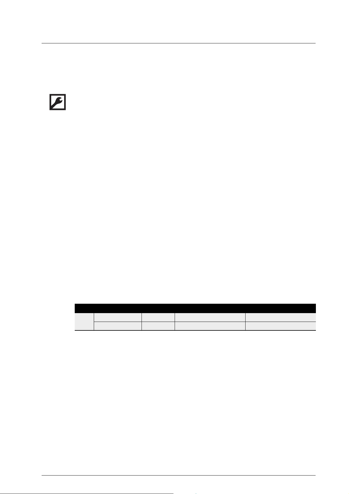
Junction box
Fig. 6 Junction box Fig. 7 Connection circuit diagram junction box
Fig. 8 OMP 32 with installed
1 Output
2 Sensor inputs
junction box standard
Fig. 9 OMP 32 with installed
junction box high temperature
42 OIO 23en Edition 10/2017 Operating Instructions

Accessories
As an option the manufacturer offers a junction box that facilitates the electrical connection of the
various sensors for the flowmeters of the OMP series. Up to three sensors can be connected. The
sensor cables are combined to form a multi-strand connecting cable which can be supplied as well
optionally if required. The detailed assignment plan can be found on the inside of the junction box lid.
The junction boxes are offered in two variants:
Appendix
Junction box
Unit
standard
□ Article no. UZA 56, UZA 57, UZA 59,
UZA 60, UZA 83, UZA 84
UZA103, UZA104
Junction box
high temperature
UZA 92
□ Housing material Aluminium Steel/Aluminium
□ Connection thread M6 M6
□ Fastening type With base plate With fastening angle
□ Used pick up BEG 56A BEG 64
□ Temperature max. [°C] 125 200
Tab. 4 Junction box – variants
Junction box standard / junction box high temperature
Use for size OMP 13 OMP 20 OMP 32 OMP 52
Electrical specification
□ 2 sensor inputs UZA103 UZA 56 UZA 59 UZA 84
□ 3 sensor inputs UZA104 /
UZA 92
UZA 57 / UZA 92UZA 60 / UZA 92UZA 83 / UZA
92
□ Outputs 1
Tab. 5 Junction box – usage and electrical specification
Operating Instructions OIO 23en Edition 10/2017 43

Accessories
2
1
6
3
4
5
1
Appendix
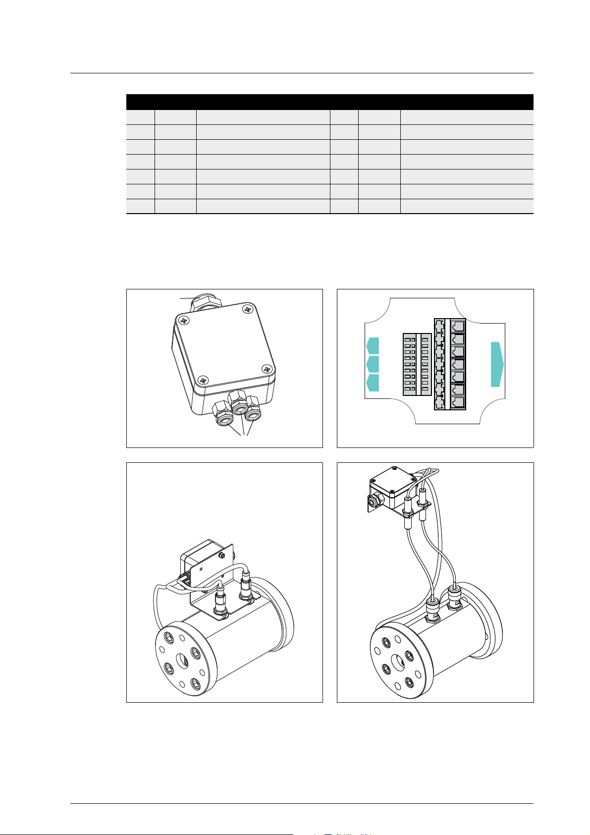
Mounting the junction box
Mounting the junction box on OMP 13 - 52
1 Cable pick up and temperature sensor
2 Connector pick up
3 Hexagon pick up
4 Washer junction box
5 Pick up inserts
6 Base plate junction box
Fig. 10 Example OMP 32
1. Disconnect the cables 1 of the pick up and the temperature sensor. Ensure that the cable length is
sufficient.
2. Unplug the connectors 2 of the pick ups.
3. Turn out the hexagon 3 of the pick ups.
4. Place the washers 4 of the junction box over the pick up inserts 5.
5. Slide the base plate 6 of the junction box under the washers 4, screw the hexagon 3 back in.
6. Plug the connectors 2 of the pick ups back in.
44 OIO 23en Edition 10/2017 Operating Instructions
Accessories
3
2
5
1
4
1
2
3
Mounting the junction box for OMP 13 - 52 high temperature
Appendix
1 Fastening angle
2 Hexagon nut amplifier
3 Amplifier
4 Cable temperature sensor and pick up
5 Pick up insert
Fig. 11 Example OMP 32
1. Disconnect the cables 4 of the pick ups with amplifier and the temperature sensor. Ensure that the
cable length is sufficient.
2. Loosen the hexagon nuts 2 of the amplifier 3.
3. Slide the amplifier 3 in the cut-out of the fastening angle 1. Ensure that the hexagon nuts lie above
and below the fastening angle.
4. Tighten the hexagon nuts.
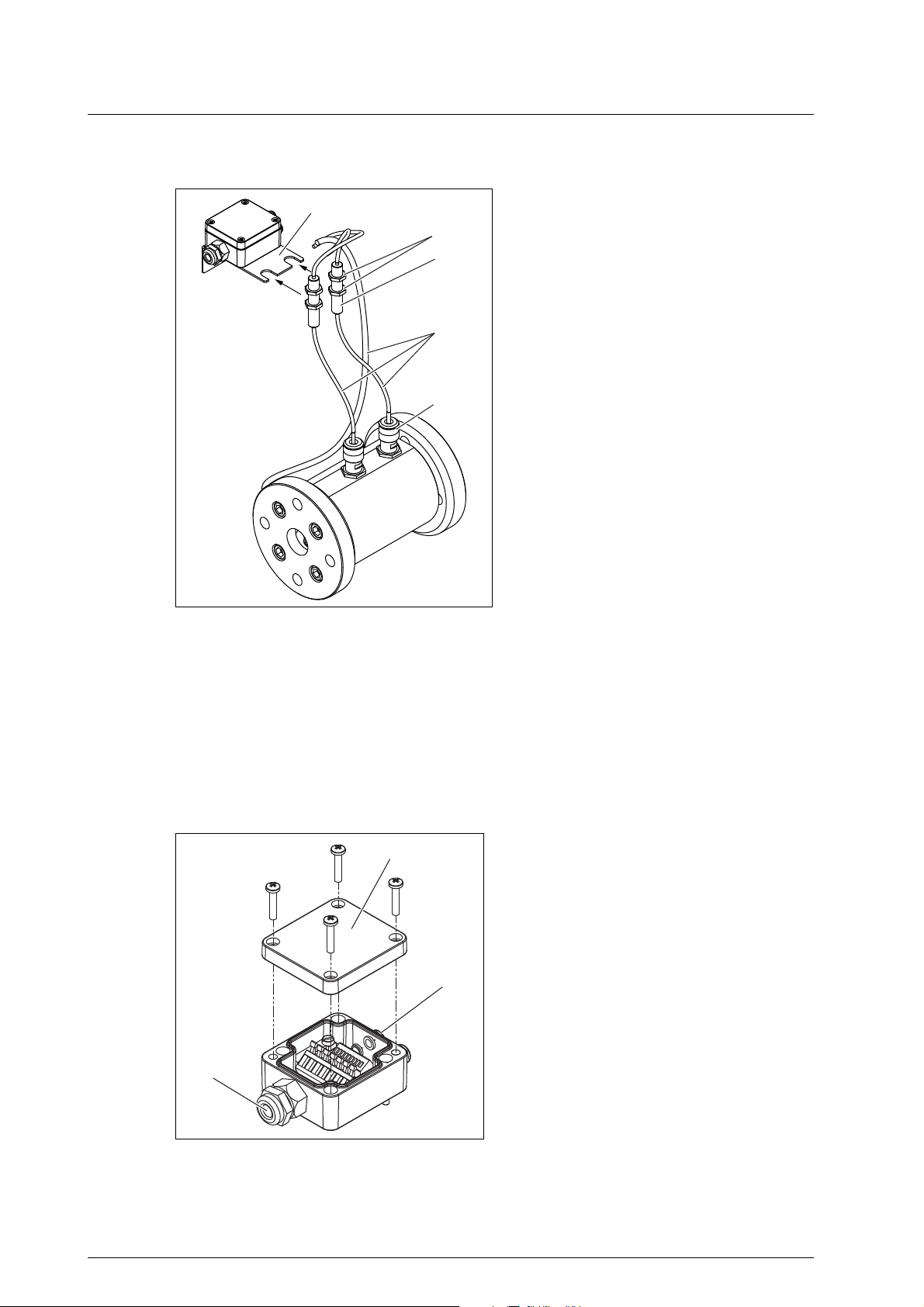
Connecting the junction box
Operating Instructions OIO 23en Edition 10/2017 45
1 Junction box lid
2 Cable glands
3 Box outlet
Accessories
Appendix
1. Dismantle the junction box lid 1.
2. Carry out the cabling of the pick up and of the temperature sensor through the cable glands 2 in the
junction box. Observe the connection circuit diagram, see Fig. 7, page 42.
3. Connect the connecting cable at the box outlet 3.
4. Screw tight the box lid 1.
Connecting the extension cable
Normally the line length does not influence the functional efficiency of the sensors. However, the
manufacturer recommends not extending the connection cable of the junction box beyond a maximum
length of 100 m. Extension cable as well as cable plug and cable box are available as accessories from
the manufacturer.
Extension cable Unit
□ Length max. [m] 100
□ Cable diameter max. [mm
2
] 9.5
□ Wire cross section
min. – max.
[mm2]
[mm2]
0.25 – 2.5 with solid wire
0.25 – 1.5 with fine wire
Pay attention to the following when connecting the extension cable:
► Use only a shielded cable.
► Lay the cable separately from the supply and measuring lines, see "Safety instructions for
electrical installation", page 25.
1. Solder cable plug to the sensor cable.
2. Solder cable box to the extension cable.
3. Connect sensor cable and extension cable.
4. Connect extension cable in accordance with the connection circuit diagram.
46 OIO 23en Edition 10/2017 Operating Instructions
Tightening torques
Tightening torques
Tightening torque [Nm] for screws with metric threads + head contact surfaces With thread measured
5.6
Thread
M 3 0.6 1.5 – 1.2 1.5 1.1 – – G 1/8" 13
M 4 1.4 2.9 4.1 2.3 3 2 – – G 1/4" 30
M 5 2.7 6.0 8.0 4.8 6.0 3.9 3.5 4.7 G 3/8" 60
M 6 4.7 9.5 14 7.6 10.3 6.9 6 8 G 1/2" 80
M 8 11.3 23.1 34 18.4 25 17 16 22 G 3/4" 120
M 10 23 46 68 36.8 47 33 32 43 G 1" 200
M 12 39 80 117 64 84 56 56 75 G 1 1/4" 400
M 14 62 127 186 101 133 89 – – G 1 1/2" 450
M 16 96 194 285 155 204 136 135 180
M 18 133 280 390 224 284 191 – –
M 20 187 392 558 313 399 267 280 370
M 24 322 675 960 540 687 460 455 605
8.8 10.9
8.8 +
Alu*
+ wedge lock
washers
Rustproof
8.8
A4-70
Stainless steel
screws A2 and A4
Property
class 70
Property
class 80
in inches
Screw plugs with
elastomer seal
Thread
* Reduced tightening
torque when screwing
into aluminum
Galvanized + stainless
Appendix
steel
Tab. 6 Tightening torques
Contents of the EC Declaration of Conformity
The flowmeters described in these operating instructions are machinery in the sense of the Directive
2006/42/EC. The original of the EC Declaration of Conformity is enclosed with the machinery at delivery.
The machinery fulfills all the relevant provisions of the following directives:
Number Name Remark
2006/42/EC Machinery Directive –
2014/68/EU Pressure Equipment Directive –
2014/30/EU Directive on Electromagnetic
Compatibility
2014/35/EU Low Voltage Directive Only for machinery with electrical
2014/34/EU Directive on Use in Potentially
Explosive Areas (ATEX)
Tab. 7 Directives observed
Only for machinery with electrical
components
components
Only for machinery in ATEX version
Operating Instructions OIO 23en Edition 10/2017 47

KRAL AG, Bildgasse 40, Industrie Nord, 6890 Lustenau, Austria,Tel.: +43/5577/86644-0
www.kral.at
KRAL AG, 6890 Lustenau, Austria, Tel.: +43 / 55 77 / 8 66 44 - 0, E-Mail: kral@kral.at
Fax: +43 / 55 77 / 8 84 33, www.kral.at, E-Mail: kral@kral.at
 Loading...