

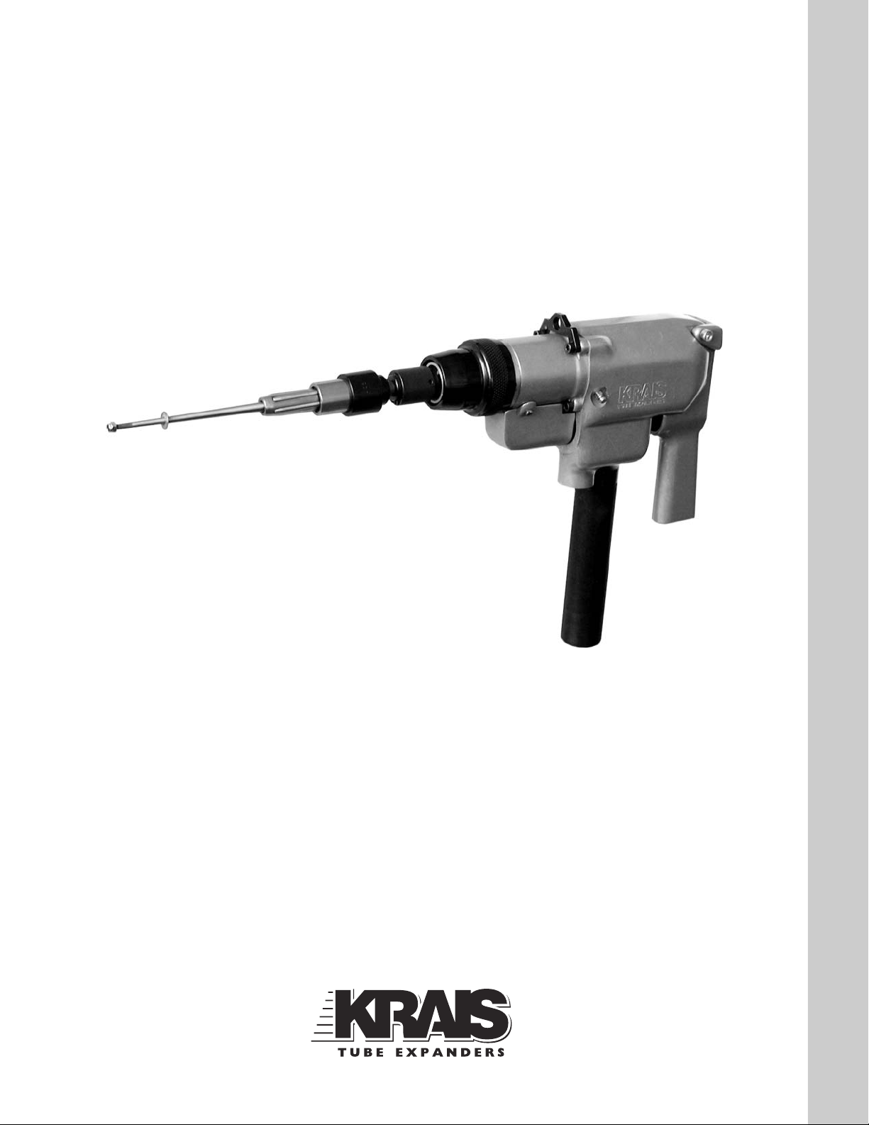
MANUAL INSTRUCTION
Model P&P K50-400, P&P K50-600,
P&P K50-1250
READ SAFETY RECOMMENDATIONS BEFORE USE , THIS TOOL
PAGE 2
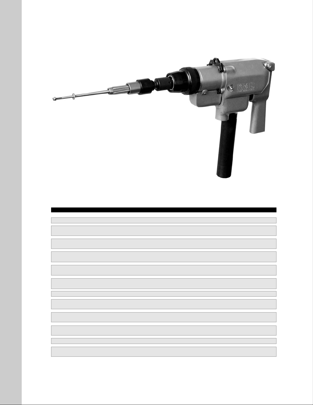
Model P&P K50-1250 P&P K50-600 P&P K50-400
Free speed 1250 rpm 600 rpm 400 rpm
Minimum torque
1,58 Nm 2,49 Nm 5,00 Nm
14 in.Lbs 22 in.Lbs 44,15 in.Lbs
Maximum torque
12,2 Nm 21,81 Nm 36,00 Nm
108 in.Lbs 193 in.Lbs 318 in.Lbs
Sound Pressure Level Lpa 83 dBa 83 dBa 83 dBa
Sound Power Level Lwa 94 dBa 94 dBa 94 dBa
Weight
4,76 kg 4,76 kg 4,76 kg
10,5 Lbs 10,5 Lbs 10,5 Lbs
Length
311 mm 311 mm 311 mm
12 1/4” 12 1/4” 12 1/4”
Side To Center Distance 1 7/16” (36.5mm) 1 7/16” (36.5mm) 1 7/16” (36.5mm)
Minimum Recommended Hose Diameter
3/8” (9.5 mm) 3/8” (9.5 mm) 3/8” (9.5 mm)
(maximum 25 Foot Length)
Air consumption
1700 l/min 1700 l/min 1700 l/min
60 cfm 60 cfm 60 cfm
Tube capacity
3/4” 1” 1 1/4”
19 mm 25,4 mm 31,7 mm
Square size 3/8” 3/8” 3/8”
Chucks
3/8” 3/8” 3/8”
opt. 1/2” opt. 1/2” opt. 1/2”
Tool Specifications
PAGE 3
For your safety and the safety of others, read and
understand the safety recommendations and
operating instructions before operating this tool.
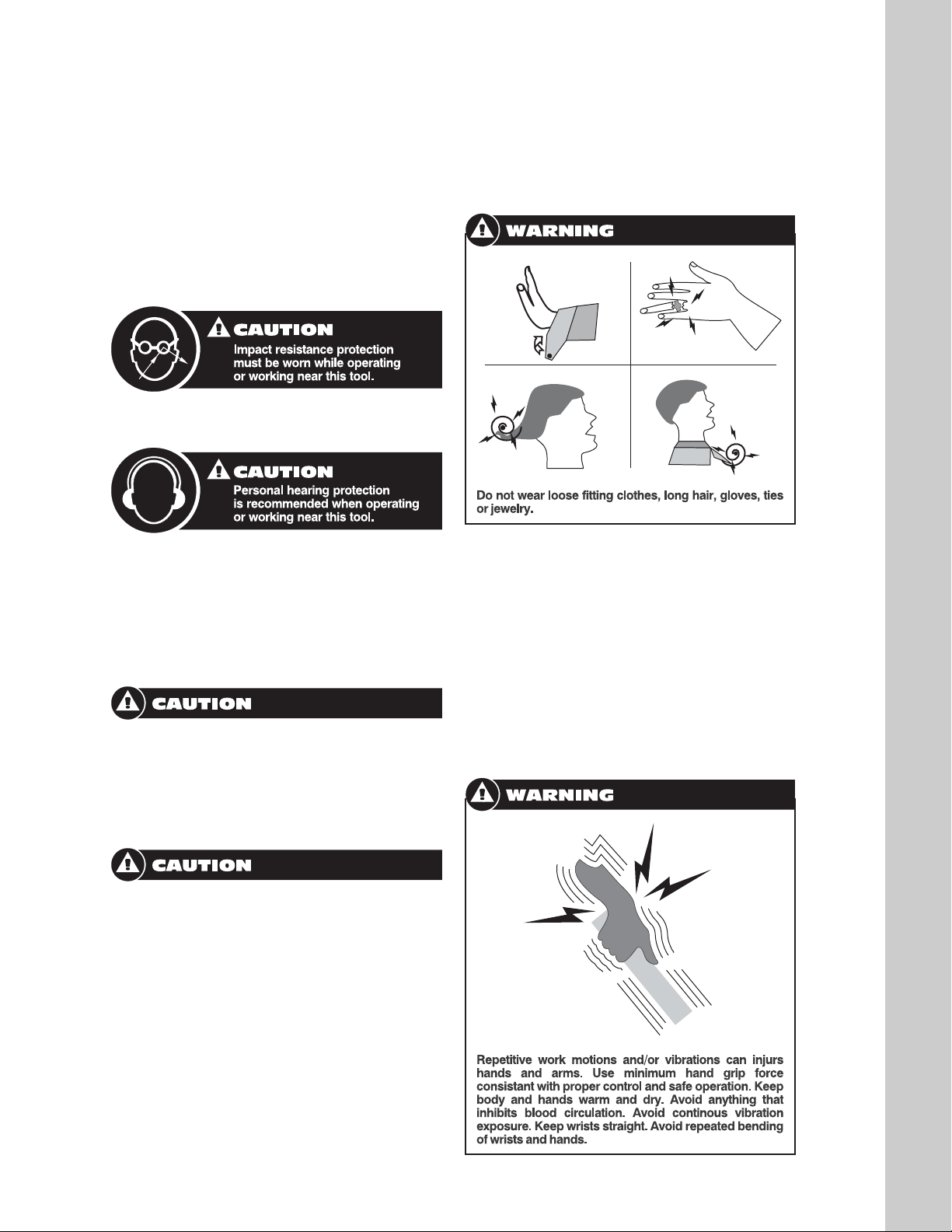
ALWAYS WEARPROTECTIVE EQUIPMENT
EYE AND FACE PROTECTION
HEARING PROTECTION
Hearing protectors are required in high noise
areas, 85 dBa or greater. The operation of other
tools and equipment the area, reflective surfaces, process noises and resonate structures,
can substantially contribute to and increase the
noise level in the area.
Moving components can entangle and enwrap.
And can result in serious injuries. Never wear
loose fitting clothes, gloves, ties or jewelry when
working with or near any power tool with an
exposed rotating shaft or spindle.
Tools with clutches can stall rather than shut-off
if adjusted over the maximum power output of
the tool, or if there is a drop in air pressure.
Operator must then resist the stall torque until
the throttle is released.
Higher torque pneumatic tools, inline and right
angle, are supplied with a torque reaction bar
designed to work with the torque of the tool it is
specified for. These bars can be braced against
the work or other suitable points to absorb and
relieve the operator of the torque reaction transmitted by the tool. Tool balance arms are also
available to absorb the torque reaction of the
tool while balancing the weight of the tool for
improved ergonomic applications.
Some individuals are susceptible to disorders of
the hands and arms when exposed to tasks, which
involve highly repetitive motions and/or vibrations.
Those individuals predisposed to vasculatory or circulatory problems may be particularly susceptible.
Cumulative trauma disorders such as carpal tunnel
syndrome and tendentious can be caused or
aggravated by repetitious, forceful exertions of the
hands and arms. These disorders develop gradually over periods of weeks, months, and years.
Safety Recommendations
TASKS SHOULD BE PERFORMED IN SUCH A
MANNER THAT THE WRISTS ARE MAINTAINED IN A NEUTRAL POSITION WHICH IS
NOT FLEXED, HYPEREXTENDED, OR TURNED
SIDE TO SIDE.
STRESSFUL POSTURES SHOULD BE AVOIDED AND CAN BE CONTROLLED THROUGH
TOOL SELECTION AND WORK LOCATION.
Any user suffering from prolonged symptoms of
tingling, numbness, blanching of the fingers, clumsiness or weakened grip, nocturnal pain in the
hand, or any other disorder of the shoulders, arms,
wrists, or fingers is advised to consult with a physician. If it is determined that the symptoms are job
related or aggravated by movements and postures dictated by the job design, it may be necessary for the employer to take steps to prevent further occurrences. These steps might include, but
are not limited to, repositioning the work piece or
redesigning the workstation, reassigning workers
to other jobs, rotating jobs, altering awork pace,
and/or changing the type of tool used so as to minimize stress on the operator. Some tasks may
require more than one type of tool to obtain the
optimum operator/tool/task relationship.
The following recommendations will help reduce or
moderate the effects of repetitive work motions:
uses a minimum handgrip force consistent with
proper control and safe operation;
keep wrists as straight as possible;
keep body and hands warm and dry.
Avoid anything that inhibits blood circulation
smoking tobacco;
cold temperatures;
certain drugs.
PAGE 4
Safety Recommendations - cont.
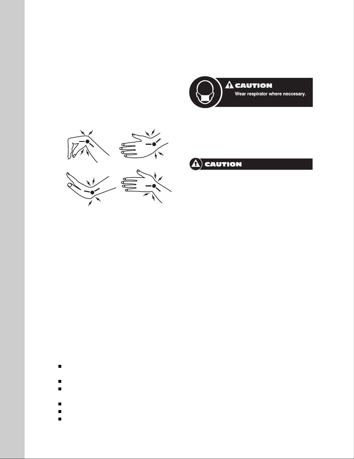
Avoid highly repetitive movements of the hands
and wrists, and continuous vibration exposure.
Use of this tool may produce hazardous fumes,
particles, and/or dust. To avoid adverse health
effects utilize adequate ventilation and/or a respirator. Read the material safety data sheet of any
materials involved in the tube expansion process.
This KRAIS product is designed to operate on minimum 90 psig (6.2 bar), maximum 125 psig (8.6)
air pressure. If the tool is properly sized and
applied, higher air pressure is unnecessary.
Excessive air pressure increases the loads and
stresses on the tool parts, mandrels, rolls and
cages and may result in premature wear and or
breakage. Installation of a filter-regulator-lubricator
in the air supply line ahead of the tool is required.
Before the tool is connected to the air supply,
check the throttle for proper operation (i.e., the
throttle moves freely and returns to the closed
"OFF" position when released). Clear the air hose of
accumulated dust and moisture. Be careful not to
endanger adjacent personnel. Before removing a
tool from service or changing sockets, make sure
the airline is shut off and drained of air. This will prevent the tool from operating if the throttle is accidentally engaged.
It is essential for safe operation that any operator of
OUR TOOLS uses good balance, sure footing, and
proper posture in anticipation of a torque reaction.
Ensure that the operator's hands will not be
wedged or pinched between the work and the tool
when operating.
NOTE: ANY USE OF THIS TOOL OTHER
THAN IT'S INTENDED PURPOSE COULD
CAUSE MAJOR DAMAGE TO THE TOOL AS
WELL AS POSE A RISK TO THE OPERATOR.

PAGE 5
Our tools are designed to operate at a minimum of 90 psi (6.2 bar) and a maximum of 125
psi (8.6 bar).
NOTE- using over 100 psi (6.8 bar) will cause
faster tool operation but will also lead to premature wear and or tool breakage of the expander
rolls and mandrel.
Fluctuation in air pressure has no effect on the
torque Control Unit, as this section is independent of the motor. A low air pressure situation
will result the tool operating slower, resulting in
longer rolling cycles.
LUBRICATIONS YOUR P&P K50 ALL
MODELS
We recommend that our Models P&P K50 are
Lubricator be used within our 15 ft supply line.
A quality grade S.A.E#10 or equivalent lubricating oil is recommended. With the P&P K50
motors running, set the lubricator to 5-10 drops
of oil per minute.
The gear section of your P&P K50 series' motor
is fitted with a pressure type grease fitting.
Approximately once four (4) weeks, pump two
(2) shots of grease into the unit using a hand
type grease gun.
CAUTION: DO NOT OVER LUBRICATE (see
above).
If excessive amount of grease are forced into
the gear section, the grease will ultimately work
its way into the motor section and will result in
sluggish tool operation.
Operating Instructions
To maintain efficient operation for continuous
use, these tools should be adjusted and serviced periodically. If accurate torque cannot be
maintained, check the shut-off trip as follows:
Remove two screws (80) holding valve cover
(79) in place. Remove cover to expose trip.
(During forward rotation the trip abuts valve (5A).
See page 10 for trip adjustment illustration.)
WARNING - REMOVE AIR SUPPLY FROM
TOOL PRIOR ANY DISASSEMBLY
Remove entire torque section as follows:
Remove 4 socket head cap screws (78). Using
tru-arc pliers, remove lock ring (162). Carefully
remove driving cam (61) and operating cam
(55). Care should be taken to prevent loss of the
balls contained in the units. Clean drive spindle
(52) and inspect for wear in the ball spline grooves. If spline is worn or dimpled, it should be
replaced. If spline and front bearing (47) show
no sign of wear, further disassembly of this unit
is unnecessary. Check follower (64) for excessive wear.
In reassembly, carefully position regulating
spring (54) on spring guide (46). Place operating
cam (55) on spindle, aligning grooves of the
spindle and grooves in the cam, Check condition of guide springs (58), place a spring in each
groove. Install five 5/32" (3.96mm) balls in each
groove. (Note: as these are extra precision
balls, no substitution should be made)
Place a small amount of grease on each angled
face of the operating cam, install inner ball retainer (57) and ball retainer (56). On each angled
face of the cam, place two of the larger balls
(60). Install driving cam (61). Do not dislodge the
balls from the helical faces. Install large lock
ring (62). The unit can then be handled in a normal manner.
To disassemble the motor package, hold the
end of the drive spider of the motor and pull
Service Instructions

PAGE 6
gear section from machine. Slide the motor
package from the unit. Disassemble the motor
package to check for wear in the cylinder liner
and to examine the motor blades. Install new
blades if the old blades show excessive wear.
Install cylinder on the end plate; check blades
(20) for proper placement; install the front bearing
support (22). Slide the motor package in place,
carefully dropping the dowel pin # 8010126
(assembled in the rear end of the cylinder) into
the locating hole at the bottom of the case. The
gear case of the 600 RPM tool is a standard twostage planetary system and disassembly and
reassemble of the unit is very simple.
Slide the gears from the gear case, clean,
inspect, re-grease and reinstall in the gear
case. Slide the gear case into the housing and
install dowel pin (39).
Reinstall the torque unit on the motor case.
(When installing the cam section on the motor
housing, be sure to depress the trip so the fol-
lower will not jam on the top side of the operating cam while aligning front case with the
motor.) Once the torque case is aligned in the
motor housing and the screws are installed, the
trip can be released. Before reinstalling the
valve cover, push forward on the operating lever
(11), and manually depress the trip. In depressing the trip with the finger. the valve (SA) will
slide forward. Simulating the operation of the
tool at shut-off. By pulling back on the lever (11).
the outer valve that surrounds the valve (SA),
should slide into the rearward position before
valve (SA) moves within. If the outer valve is tight
to the degree of sticking in the bushing (1) the
motor would run forward rather than in reverse,
causing over-rolling of joints. It is therefore
essential that the outer valve be free in the
bushing.
After the above checks have been made, reinstall the valve cover. Ensure adequate lubrication of al parts during reassembly.
Service Instructions - cont.
MODEL K50-600 K50-1250 K50-400
ITEM DESCRIPTION PART NUMBER QTY PART NUMBER QTY PART NUMBER QTY
1 BUSHING K-850-27 1 K-850-27 1 K-850-27 1
2 LOCK NUT K-850-19 1 K-850-19 1 K-850-19 1
3 CASE K-850-1-RE 1 K-850-1-RE 1 K-850-1-RE 1
*4 SPRING K-850-22 1 K-850-22 1 K-850-22 1
*4A SHAFT SEAL K-850-70 1 K-850-70 1 K-850-70 1
*4B "O" RING K-500-31 1 K-500-31 1 K-500-31 1
*4C "O" RING K-RTV-65 1 K-RTV-65 1 K-RTV-65 1
5 CAM CASE K-900-2-A 1 K-900-2-A 1 K-900-2-A 1
*5A VALVE K-850-21-A 1 K-850-21-A 1 K-850-21-A 1
*5B "O" RING K-200-16 1 K-200-16 1 K-200-16 1
*5C "O" RING K-2-011 1 K-2-011 1 K-2-011 1
6 LOCK RING K-402-S-24 1 K-402-S-24 1 K-402-S-24 1
7 CAP K-850-26 1 K-850-26 1 K-850-26 1
8 PIN K-850-34 1 K-850-34 1 K-850-34 1
9 BUSHING K-850-1-B 2 K-850-1-B 2 K-850-1-B 2
10 TRIP GAUGE K- 1 K- 1 K- 1
10A DIRECTION VALVE K-850-28-A 1 K-850-28-A 1 K-850-28-A 1
10B "O" RING K-2-020 2 K-2-020 2 K-2-020 2
11 LEVER K-850-1-L 1 K-850-1-L 1 K-850-1-L 1
12 LEVER PIN K-850-35 1 K-850-35 1 K-850-35 1
13 SELF LOCK NUT K-1/4"-28 or (M-6) 1 K-1/4"-28 or (M-6) 1 K-1/4"-28 or (M-6) 1
14 TRU-ARC RING K-402-23 1 K-402-23 1 K-402-23 1
15
16 BEARING K-300-G-29 1 K-300-G-29 1 K-300-G-29 1
17 REAR THRUST K-1000-74 1 K-1000-74 1 K-1000-74 1
18 ROTOR K-1000-73-700-S 1 K-1000-73-S 1 K-1000-73-700-S 1
19 TRU-ARC RING K-500-24 1 K-500-24 1 K-500-24 1
20 BLADES K-1000-72-S 4 K-1000-72-S 4 K-1000-72-S 4
21 CYLINDER K-1000-71-S 1 K-1000-71-S 1 K-1000-71-S 1
22 FRONT THRUST K-900-7-45 1 K-900-7 1 K-900-7-45 1
23 BEARING K-400-13 1 K-300-G-29 1 K-400-13 1

MODEL K50-600 K50-1250 K50-400
ITEM DESCRIPTION PART NUMBER QTY PART NUMBER QTY PART NUMBER QTY
24
25 BEARING K-400-16 4 K-400-16 4 K-400-16 4
26 PLANET GEAR K-500-12-30 2 K-900-12 2 K-500-12-400 2
27 PLANET PIN K-500-18 2 K-900-18 2 K-500-18 2
28 SPIDER K-900-25-45-1 1 K-900-25 1 K-900-25-400-1 1
29 BEARING K-1000-88 1 K-900-3 1 K-1000-88 1
30 BEARING K-400-16 6 N/A K-400-16 6
31 PLANET GEAR K-500-12-40 3 N/A K-500-12-400 3
32 PLANET PIN K-500-18 3 N/A K-500-18 3
33 GEAR SPIDER K-900-25-45 1 N/A K-900-25-400 1
34 GEAR HAUSING K-900-20-45 1 K-900-20 1 K-900-20-400 1
35 BEARING SUPPORT K-900-58-45 1 K-900-58 1 K-900-58-45 1
36 REAR BEARING K-700-9 1 K-700-7 1 K-700-9 1
37 TRU-ARC RING K-900-15 1 K-900-15 1 K-900-15 1
38
39 PIN K-900-19 1 K-900-19 1 K-900-19 1
40 CAM KEY K-900-53 1 K-900-53 1 K-900-53 1
41 BEARING K-500-13 1 K-500-13 1 K-500-13 1
42 TRU-ARC RING K-900-6 1 K-900-6 1 K-900-6 1
43 PRESSURE PIN K-900-10 3 K-900-10 3 K-900-10 3
44 PRESSURE PAD K-900-11 1 K-900-11 1 K-900-11 1
45 BEARING K-1000-64 1 K-1000-64 1 K-1000-64 1
46 SPRING GUIDE K-900-13 1 K-900-13 1 K-900-13 1
47 FRONT BEARING K-900-14 1 K-900-14 1 K-900-14 1
48
49 TRU-ARC RING K-900-15 1 K-900-15 1 K-900-15 1
50 LOCK RING K-900-45 1 K-900-45 1 K-900-45 1
51 SOC SET SCREW K-8-32X1/8" 1 K-8-32X1/8" 1 K-8-32X1/8" 1
52 SPINDEL K-900-4 K-900-4 K-900-4
53 TRU-ARC RING K-900-5 1 K-900-5 1 K-900-5 1
54 SPRING K-850-44 1 K-850-44 1 K-850-44 1
55 OPERS TING CAM K-900-49 1 K-900-49 1 K-900-49 1
56 RETAINER K-1000-52 1 K-1000-52 1 K-1000-52 1
57 BALL RETAINER K-900-52 1 K-900-52 1 K-900-52 1
58 GUIDE SPRING K-900-47 3 K-900-47 3 K-900-47 3
59 STEEL BALL K-900-48 15 K-900-48 15 K-900-48 15
60 STEEL BALL K-1000-48 6 K-1000-48 6 K-1000-48 6
61 CAM K-900-54 1 K-900-54 1 K-900-54 1
62 TRU-ARC RING K-900-24 1 K-900-24 1 K-900-24 1
63 TRIP K-850-18 1 K-850-18 1 K-850-18 1
64 FOLLOWER K-900-17 1 K-900-17 1 K-900-17 1
65 SPRING K-1000-16 1 K-1000-16 1 K-1000-16 1
66
67 PIN K-1000-37 1 K-1000-37 1 K-1000-37 1
68 HEX NUT K-6-32 1 K-6-32 1 K-6-32 1
69 SOC SET SCREW K-6-32X1/2" 1 K-6-32X1/2" 1 K-6-32X1/2" 1
70 QUICK CHANGE CHUCK K-850-375 1 K-850-375 1 K-850-375 1
71 SPLIT PIN K-1/8"X7/8" 1 K-1/8"X7/8" 1 K-1/8"X7/8" 1
72 ADJUSTING NUT K-900-43 1 K-900-43 1 K-900-43 1
73 NYLON TIP SET SCREW K-8-32X3/16 1 K-8-32X3/16 1 K-8-32X3/16 1
74 "O" RING K-2-033 1 K-2-033 1 K-2-033 1
75
76
77 BRACKET K-900-56 1 K-900-56 1 K-900-56 1
78 BUTTON HD CAP SCREW K-M-6X22 2 K-M-6X22 2 K-M-6X22 2
78 BUTTON HD CAP SCREW K-M-6X16 2 K-M-6X16 2 K-M-6X16 2
78A MED. LOCK WASHER K-10 4 K-10 4 K-10 4
79 COVER K-850-1-C 1 K-850-1-C 1 K-850-1-C 1
80 BUTTON HD CAP SCREW K-6-32X3/8" 2 K-6-32X3/8" 2 K-6-32X3/8" 2
80 EX TYPE LOCK WASHER K-6 2 K-6 2 K-6 2
81 QC NIPPLE K-HOF 1 K-HOF 1 K-HOF 1
82 CLOSE NIPPLE K-1/2" 1 K-1/2" 1 K-1/2" 1
83 MUFFLER COMPLETE K-A-850-61-MF 1 K-A-850-61-MF 1 K-A-850-61-MF 1
84 PLUG K-1000-42 1 K-1000-42 1 K-1000-42 1
85 ZERK K-1/4"-28 1 K-1/4"-28 1 K-1/4"-28 1
86 QC COUPLER K-EZ-308F-8L 1 K-EZ-308F-8L 1 K-EZ-308F-8L 1
100 REACTION BAR K-50-400 1
PAGE 7

PAGE 8
Push&Pull K50-1250

PAGE 9
Push&Pull K50-600

PAGE 10
Push&Pull K50-400

PAGE 11
The Trip Mechanism on our Model P&P K50600, P&P K50-400 and P&P K50-1250, has an
overall confined travel of 0,118" (3mm). For proper operation, the trip mechanism should be set
to a maximum engagement of 0,062" (1,57mm)
with the abutting valve plunger. (See Diagram)
The above adjustment allows the valve to shut
off at the mid-point of the total trip movement of
the tool.
Model K50-... Trip Adjustment
We recommend that this adjustment be made
with the tool running in the clockwise direction,
with the Torque Adjustment Nut on digit 5 and
no load being placed on the tool.
Our Adjustment Gauge is recommended to
ensure the correct set up of the trip mechanism
(See drawing)

PAGE 12
The following suggestions are offered to aid in
the setting up process for rolling tubes into a
heat exchanger, condenser or boiler. A good
start insures good result.
A) Pick 3 to 5 tubes in the unit to be rolled and
complete the worksheet on the back of this
page. It is important that the measurements
used in the set-up are actual. Never use average dimensions.
B) After the worksheet is finished, start setting
up the torque control motor by test rolling the
first of the tubes. The first test roll must be done
with the rolling motor set for low torque to avoid
over rolling.
C) Measure the tube I.D. after rolling if more
expansion is needed increase the torque setting
on the control and roll the second tube. Check
the finished I.D. This step may have to me repeated on tube #3 by this time, the torque setting
should be corrected.
D) Roll tubes 4 and 5 to double check the setup. These tubes should measure as calculated
within the allowable tolerance.
- Condenser tubes 10 to 17 ga
(3.4mm to 1.5mm ± 0.001" / 0.025mm)
- Condenser tubes 18 to 24 ga
(1.25mm to 0.5mm ± 0.0005" / 0.012mm)
- Boiler tubes 4 to 10 ga
(6.5mm to 3.4mm ± 0.002" / 0.05mm)
- Boiler tubes 12 to 18 ga
(2.8 mm to 1.25 mm ± 0.001" / 0.025mm)
IMPORTANT: REROLL ALL THE TEST
TUBES THAT WERE UNDER SIZE.
E) The rolling control is now set and ready to roll
the rest of the tubes in the unit. The use of the
torque control system will ensure the uniform
tightness of all tubes.
IMPORTANT NOTE:
TO ENSURE THE BEST TOOL LIFE AND THE
HIGHEST QUALITY TUBE TO TUBE SHEET
CONTACT, PERIODIC CLEANING OF THE
EXPANDER IS NECESSERY. PROPER
LUBRICATION OF THE ROLL MANDREL
AND THRUST BEARING IS A MUST!
LUBRICATION OF THE TUBE EXPANDERS
A quality lubrication oil, SAE#10 grade is popular
for Tube expansion in normal tube size. For sever
rolling of heavy gauge tubes or alloy materials a
Viscous heavy oil of approximately SAE#60 is
recommended. We can also supply water-soluble lubricant, our part number KAT-128.
Tube Rolling Procedure

PAGE 13
CONDENSER TUBES ......5% REDUCTION
BOILER TUBES..............10% REDUCTION
TESTS PROVE THAT SATISFACTORY JOINTS
ARE PRODUCED USING THE ABOVE LISTED
PERCENTAGE OF TUBE WALL REDUCTION.
Tube sheet hole (measure)............................ h
Tube O.D. (measure) .................................... b
CClleeaarraannccee ........................................................................................
c = h-b
Tube ID (measure) ........................................ d
WWaallll tthhiicckknneessss ........................................................................
w = b-d
55%% wwaallll rreedduuccttiioonn ............................................
f = (0.05 x w)
FFiinniisshheedd II..DD ........................................................
g = (c + d + f)
STEP TUBE # Example 1 2 3 4 S
1 Tube Sheet Hole .760" (19,3 mm)
2 - Tube O.D. .750" (19,05 mm)
3 = Clearance .010" (2,54 mm)
4 + Tube I.D. .620" (15,74 mm)
5 Wall Thickness (TOT) .130" (3,3 mm)
6 + 5% Wall Reduction .006 (0,152 mm)
7 = Finished I.D. .636 (16,15 mm)

PAGE 14
STEP TUBE # Example 1 2 3 4 S
1 Tube Sheet Hole .760" (19,3 mm)
2 - Tube O.D. .750" (19,05 mm)
3 = Clearance .010" (2,54 mm)
4 + Tube I.D. .620" (15,74 mm)
5 Wall Thickness (TOT) .130" (3,3 mm)
6 + 5% Wall Reduction .006 (0,152 mm)
7 = Finished I.D. .636 (16,15 mm)
STEP TUBE # Example 1 2 3 4 S
1 Tube Sheet Hole .760" (19,3 mm)
2 - Tube O.D. .750" (19,05 mm)
3 = Clearance .010" (2,54 mm)
4 + Tube I.D. .620" (15,74 mm)
5 Wall Thickness (TOT) .130" (3,3 mm)
6 + 5% Wall Reduction .006 (0,152 mm)
7 = Finished I.D. .636 (16,15 mm)
STEP TUBE # Example 1 2 3 4 S
1 Tube Sheet Hole .760" (19,3 mm)
2 - Tube O.D. .750" (19,05 mm)
3 = Clearance .010" (2,54 mm)
4 + Tube I.D. .620" (15,74 mm)
5 Wall Thickness (TOT) .130" (3,3 mm)
6 + 5% Wall Reduction .006 (0,152 mm)
7 = Finished I.D. .636 (16,15 mm)

PAGE 15
Warrants the pneumatic rolling motors
model P&P K50-600, P&P K50-400 and P&P
K50-1250 for one (1) year from the shipping
date, against defects in material and workmanship. For warranty evaluation, contact
your local supplier. Tools returned for warranty evaluation have to be shipped prepaid
to your nearest distributor or our company. If
returned product is found to be covered
under warranty, it will be returned shipped
prepaid in the same way as received.
Warranty

Przedsiębiorstwo Produkcyjno-Remontowe KRAIS
Poland, 55-106 Zawonia, Czachowo 15
tel. +48 71 312 05 96, fax +48 71 387 03 32
http://www.krais.pl, email: expanders@krais.pl
 Loading...