

Page 1

MODULAR IRRIGATION CONTROLLER
INSTALLATION, PROGRAMMING
AND OPERATION MANUAL
Page 2

www.krain.com
This unit has been designed to provide
protection against harmful interference in
a residential install. This equipment uses,
generates and can radiate radio frequency
energy and, if not installed and used in
accordance with the instructions, may cause
harmful interference to radio communications.
There is no guarantee that interference will
not occur in any particular install.
If the equipment does cause harmful
interference to radio or television reception,
which can be determined by turning the
equipment off and back on again, the
user is encouraged to try to correct the
interference by:
(1) reorient or relocate the receiving antenna;
(2) increase the separation between the
equipment and receiver;
(3) connect the equipment into an outlet on
a different circuit from the receiver;
(4) consult the dealer or an experienced
radio / TV technician for help.
Changes or modifications to this equipment
could void the user’s authority to use the
equipment as well as the warranty.
INTRODUCTION
The Pro-LC Controller is available as indoor
or outdoor models. The unit consists of a
master valve/pump start, common, sensor
terminals and station modules which will
operate up to 12 electric valves.
DECLARATION OF CONFORMITY
01
Page 3

Controls and Push Button 03
Setting the Controller to Off 04
Set Controller to Run Automatically 04
Program Select Button 04
Rain Sensor Button 05
Programming 05
Set Current Time/Date 06
Set Program Start Times 07
Set Watering Days 07
Set Custom Operation 08
(any day of the week)
Set Odd/Even Operation 08
(calendar day)
Set Station Run Times 09
Manual Program Operation 09
Running a Single Station Manually 10
Valve Locator 10
Test All Stations 11
Special Features 12
Seasonal Adjust 12
Station Delay/Overlap 12
Pump On/Off 13
Sensor 13
Clear 14
Save 14
Restore 15
Permanent Day Off 16
Program Display 16
Installation 17
Door Removal 17
Mounting the Controller 18
Field Wire Entrances 18
Connecting Valve Wires 19
Pump Start/Master Valve Wiring 20
Rain Sensor Installation 20
Powering the Controller 21
Specifications 22
Operating Specifications 22
Electrical Specifications 22
Dimensions 22
Troubleshooting 23
Spare Watering Planner 25
Warranty back cover
02
CONTENTS
Page 4

www.krain.com
CONTROLS AND PUSH BUTTON
03
ERROR/ALARM LED
turns on when one of
the following occurs:
Watering is suspended
by a sensor
The controller senses
a valve short circuit
A programming error
has been made.
PROGRAM DIAL
Used to turn the controller
on and off and to program.
Used to run on Automatic
and to discontinue
watering (OFF)
Used to select desired
controller setting
functions (SET)
Shows total content of
a program (PROGRAM
DISPLAY)
Used to allow setting
controller special
features (SPECIAL
FEATURES)
Used to run single
stations or system
test cycles (RUN)
LCD DISPLAY
Displays the time of day
and day of the week
During programming
shows the results of
entered commands
During watering shows
the valve that is on and
the minutes remaining
in its run time
DOWN / UP BUTTONS
Used to set time / date and to make
program changes.
MANUAL START / NEXT BUTTON
Used to start a selected irrigation
program manually, or to manually
advance watering from one
station valve to the next.
PROGRAM SELECT BUTTON
Used to select watering
program A, B or C.
SENSOR BYPASS SELECT BUTTON
Used to tell the controller to obey
or ignore sensor input.
PROGRAM
SELECT
BUTTON
ERROR /
ALARM LED
SENSOR
BYPASS SELECT
BUTTON
PROGRAM DIAL
MANUAL
START/NEXT
BUTTON
BACK
BUTTON
DOWN
BUTTONUPBUTTON
LCD DISPLAY
1
2
3
1
2
3
4
5
6
1
2
3
Page 5

1. Turn the dial to “OFF”
When the dial is in the “OFF” position no
watering occurs. The display will show “OFF,”
the time of day and day of the week.
NOTE: Pressing any button will momentarily
display the current “REVISION NUMBER,”
“K-RAIN” or full display screen.
SET CONTROLLER TO RUN AUTOMATICALLY
1.Turn the dial to “AUTO”
When the dial is in the “AUTO” position
the controller will run in automatic mode.
The display will show the selected program,
the day of the week and the time of day.
The controller will turn on automatically to
meet ANY programmed water schedules.
The Pro-LC controller has three
separate programs, A, B and C.
Multiple programs allow valves
automatic operation with different
watering days and start times.
You can program any valve to run in
one or more of the three programs.
1. To select a program, press the
PROGRAM select button on the front
panel to select program A, B or C.
2. The display briefly shows the
program selected.
3. The selected program then appears
on the left side of the display.
4. Any programming instructions
entered will apply only to the
selected program.
04
SETTING THE CONTROLLER TO OFF PROGRAM SELECT BUTTON
OFF 9:10
AM
FRI
FRI 9:09
AM
a
pgm
Page 6

www.krain.com
RAIN SENSOR SELECT BUTTON PROGRAMMING
05
The purpose of a rain sensor is to stop automatic
watering when sufficient precipitation has been
reached.
The rain sensor select button allows the user
to bypass the rain sensor. If a rain sensor has
been installed, and BYPASSED has been selected,
then BYPASSED will be displayed in the upper
left corner of the LCD.
NOTE: When the rain sensor select button is
in the ON position a rain sensor or wire jumper
must be installed in order to run a program.
Refer to page 13 for further details.
As the program dial is rotated the display
automatically changes. The flashing value within the
display can be increased or decreased by pressing
the DOWN or UP buttons. To go back or advance to
the next value press the BACK or NEXT buttons.
Because of variations in plant watering needs the
Pro-LC has three separate programming options;
A, B and C. Each program is completely independent
of each other and the controller will automatically
stack programs that overlap. This allows for all
programmed watering to occur because only one
program will run at a time and in alphabetical order.
Only one start time per program (A, B or C) is
required to operate all stations with a run time.
The controller automatically and numerically
advances operation to the next station without
the need for additional start times.
For additional watering, each program can be set with
up to four separate start times. This allows for greater
irrigating efficiency when all watering can’t be done
during a single operation (cycle and soak).
NOTE: A program must contain at least one start
time, watering day(s) and one station with a run
time in order to operate.
WED 10:26
AM
A
PGM
BYPASSED
Page 7

1. Turn the dial to SET TIME / DATE, the LCD will
display the time of day. The word “HRS” will be
flashing in the display.
2. Press DOWN or UP buttons to set current hour.
3. To change minutes, press the NEXT button.
The word “MIN” will be flashing in the display.
4. Press DOWN or UP buttons to set current minutes.
5. To set the current date, press the NEXT button.
The word “DAY” will be flashing in the display.
6. Press DOWN or UP buttons to set current day.
7. To set the current month press the NEXT button.
The word “MONTH” will be flashing in the display.
8. Press DOWN or UP buttons to set current month.
9. To set the current year press the NEXT button.
The word “YEAR” will be flashing in the display.
10. Press DOWN or UP buttons to set current year.
11. Return the dial to AUTO.
NOTE: The
Pro-LC controller can be set for either
12 or 24 hour display. Pressing the BACK and NEXT
buttons SIMULTANEOUSLY will allow user to toggle
between 12 or 24 hour display.
06
SET TIME / DATE
9:10
AM
TIME
HOURS MINUTES
28FEB12
FRI
DAY MONTH YEAR
Page 8

www.krain.com
The Pro-LC controller will allow up to four separate
watering start times for each program.
1. Use the PROGRAM SELECT BUTTON to select
the program (A, B or C) you wish to assign a
start time.
2. Turn the dial to SET PROGRAM START TIMES.
The display will show the first start time currently
set for the selected program.
3. Press DOWN or UP buttons to change start time.
The time setting change is in 15-min. increments.
4. To eliminate a watering start time, press DOWN
or UP buttons until “OFF” appears in the display.
The OFF setting is located between 11:45 p.m. and
12:00 a.m.
5. When additional start times are needed press NEXT
button to display next watering start time. Repeat
steps 4 through 6 for setting additional start times.
6. Return the dial to AUTO.
The Pro-LC controller can be programmed to
operate within four different watering cycles.
CUSTOM waters on the days of the week
you select.
ODD waters only on odd number days of
the month.
EVEN waters on even numbered days of
the month.
SET PROGRAM START TIMES SET WATERING DAYS
07
1ST 8:00
AM
A
PGM
START TIME 1
Page 9

1. Use the PROGRAM SELECT BUTTON
to select the program (A, B or C) you
wish to assign watering days.
2. Turn the dial to SET WATERING
DAYS. “MON ON” should appear in
the display.
3. Press the DOWN or UP buttons to
enable (ON) or disable (OFF) day of
the week operation.
4. Press the NEXT button to advance to
the next day of the week. Repeat steps
3 and 4 until all days of the week have
been set.
5. Return the dial to AUTO.
1. Use the PROGRAM SELECT BUTTON
to select the program (A, B or C) you
wish to assign odd or even watering.
2. Press the BACK and NEXT buttons
SIMULTANEOUSLY until “ODD” or
“EVEN” appears in the display.
3. Return the dial to AUTO.
08
SET CUSTOM OPERATION SET ODD/EVEN OPERATION
ODD
A
PGM
days
even
A
PGM
days
MON ON
A
PGM
DAYS
MON TUE WED THU FRI SAT SUN
Page 10
www.krain.com
Stations 1–12 can be set to run from one second
up to six hours. The first hour settings are in one
minute increments. The remaining five hours can
be set in ten minute increments.
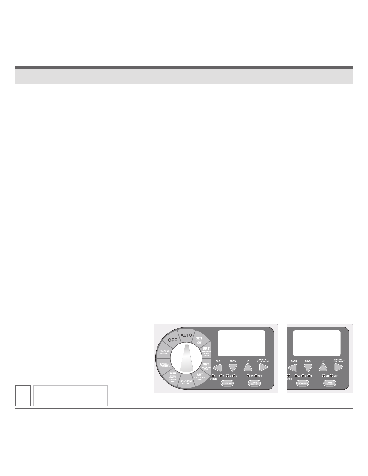
1. Use the PROGRAM SELECT BUTTON to select the
program (A, B or C) you wish to assign a run time.
2. Turn the dial to SET STATION RUN TIMES.
The display will show all available stations
(module must be installed). The first available
station number will be flashing.
3. Press the DOWN or UP buttons to set the number
of seconds/minutes/hours you wish the station to
operate (run time). For stations that don’t require
a run time set to “OFF.”
4. Press the NEXT button to advance to the next
station number in sequence. Repeat steps 3 and
4 until you have set a run time for each desired
station in the selected program.
5. Return the dial to AUTO.
NOTE: Station run times can be set to run in either
hours/minutes or minutes/seconds. Press BACK and
NEXT buttons SIMULTANEOUSLY to toggle
between setting.
When a full program operation is needed the user can
manually start any of the three (A, B or C) programs.
1. Use the PROGRAM SELECT BUTTON to select the
program (A, B or C) you wish to manually operate.
2. Turn the dial to AUTO or RUN PROGRAM.
3. Press MANUAL START / NEXT button to start the
selected program.
4. The display will show “RUN,” the station
currently running and the remaining run time
for that station. As each station completes its
previously programmed run time the next station
in sequence will begin watering.
5. Manual operation can be cancelled anytime
by turning the dial to OFF for 3 seconds.
6. Return the dial to AUTO.
NOTE: Pressing BACK or NEXT buttons will manually
advance to the next or previous station number.
Previously programmed run times can be increased
or decreased during manual operation. Any run time
changes during manual operation WILL NOT
change the station’s stored program run time.
SET STATION RUN TIMES MANUAL PROGRAM OPERATION
09
FRI 9:09
AM
a
pgm
starT
A
PGM
-
-
Page 11
When only a single station operation is needed, the
user can manually start a specific station.
1. Use the PROGRAM SELECT BUTTON to select the
program (A, B or C) that contains the station you
wish to manually operate.
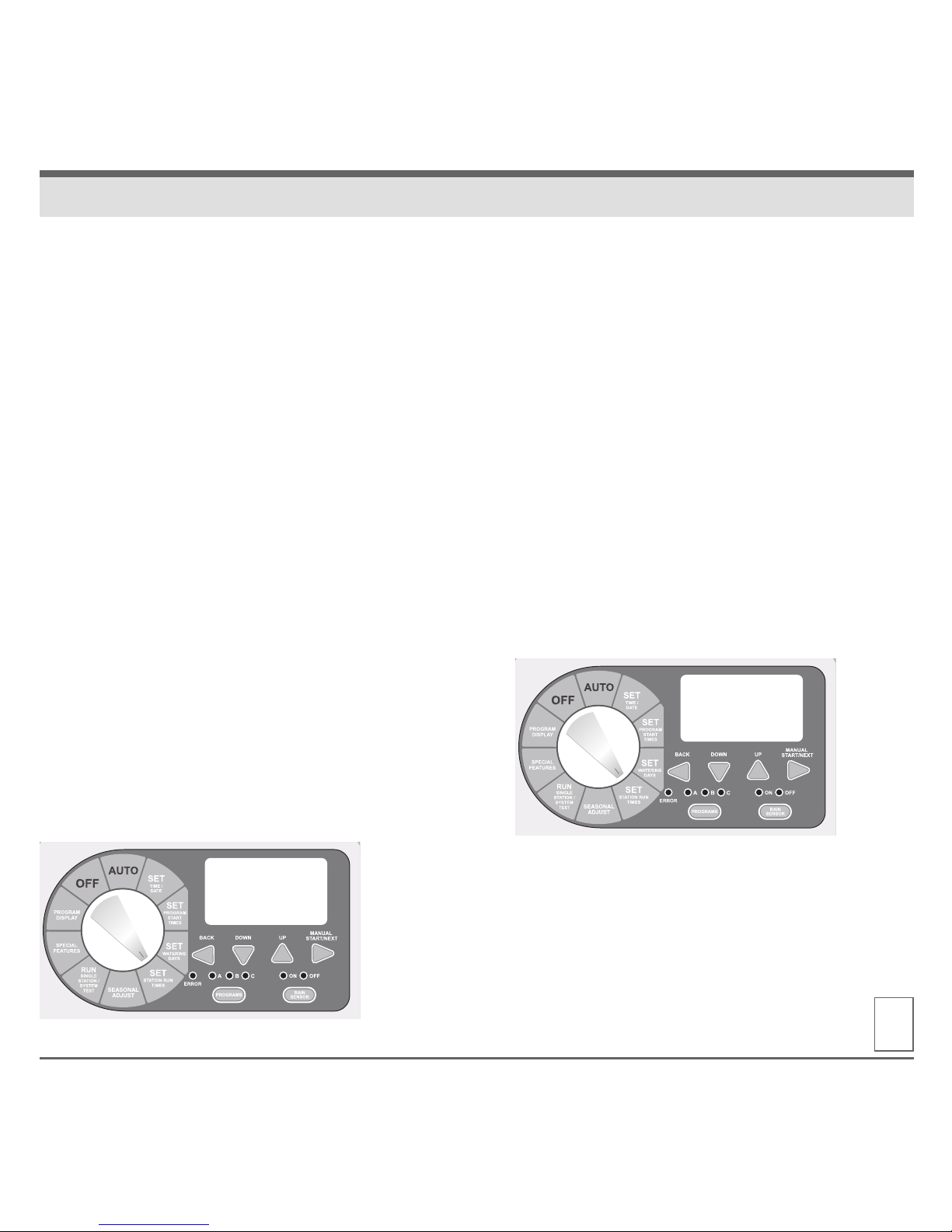
2. Turn the dial to RUN SINGLE STATION. Display
shows selected program and word “SINGLE.”
Press NEXT to enter single station operation.
3. Press UP or DOWN to select desired station.
4. Press MANUAL START to begin station operation.
NOTE: Pressing BACK or NEXT buttons will manually
advance to the next or previous station number.
Previously programmed run times can be increased
or decreased during manual operation. Any run time
changes during manual operation WILL NOT
change the station’s stored program run time.
If station has a zero run time (OFF) use PROGRAM
SELECT BUTTON to select a different program.
Stations with a zero run time (OFF) can not be
manually activated. Only stations with a previously
programmed run time can be manually started.
Locating a valve in an irrigation system may be
needed for maintenance or repair. Without the
correct tools locating the valves can be time
consuming.
The Pro-LC controllers locate feature helps the user
find buried valves by pulsing the valves solenoid.
1. Turn the dial to RUN SINGLE STATION/SYSTEM
TEST. The display will show selected program
and “SINGLE.” Press the UP or DOWN buttons
until display shows “LOCATE.”
2. Press the MANUAL START button to begin the
locate feature. The display will now show the
available station.
3. Press the MANUAL START button to advance
to the next available station.
10
RUNNING A SINGLE STATION MANUALLY VALVE LOCATOR
SINGLE
a
pgm
LOCATE
Page 12
www.krain.com
The Pro-LC controller allows the user a quick and
simple method for checking all available stations by
running a test program. This feature operates each
station individually in numerical order starting with
the lowest available station.
Station operation is preset for a two minute run time
which the user can alter at anytime during the test.
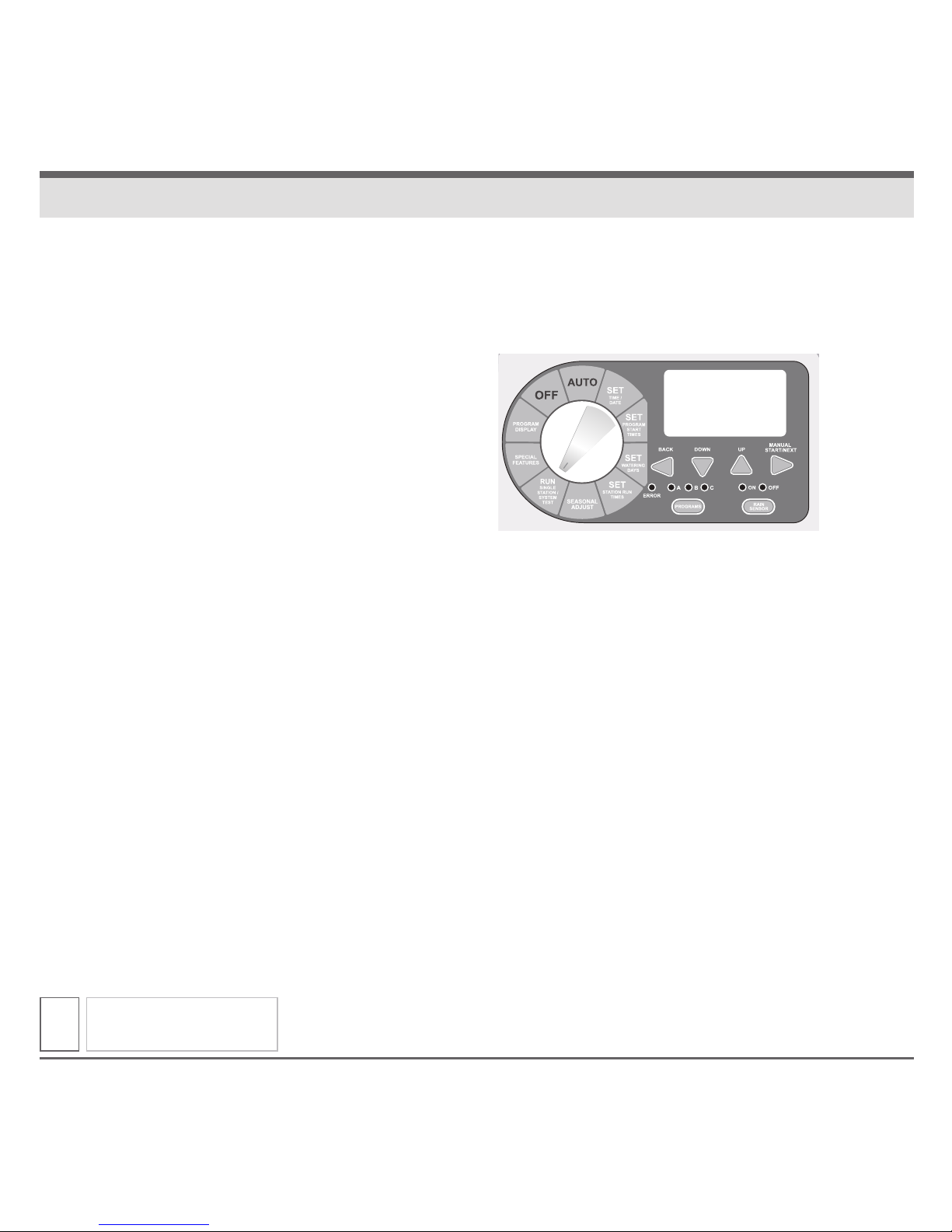
1. Turn the dial to SYSTEM TEST. Display will show
selected program and “SINGLE.” Press UP or
DOWN buttons until display shows “TEST.”
2. Press the MANUAL START button to begin the
test feature. The display will now show “RUN”
along with its remaining run time for the first
available station.
3. To change default test time press UP or DOWN.
While the test program is running the display
shows the station number currently operating,
along with its remaining run time. The controller
will run each station in numerical sequence.
4. Press the NEXT button to manually advance to
the next available station.
NOTE: Changing the test run time can be done
at any time and for any station during the test.
Any change to the test run time becomes the
new default for all stations.
TEST ALL STATIONS
11
TEST
Page 13
SEASONAL ADJUST
The seasonal adjust feature allows the user to
increase or decrease station run times globally,
for all stations, without re-programming each
individual station. Run times can be reduced to
as little as 10% or as high as 200%.
This feature is used to decrease or increase
watering times during seasonal temperature
changes. The seasonal adjust % is calculated
on the programmed run time for each station.
For example: if a station is programmed to run
10 minutes, and the seasonal adjust is adjusted
downward 80%, the station will now run for
8 minutes. Conversely, if you set the adjustment
upwards to 120%, the same station will now run
for 12 minutes.
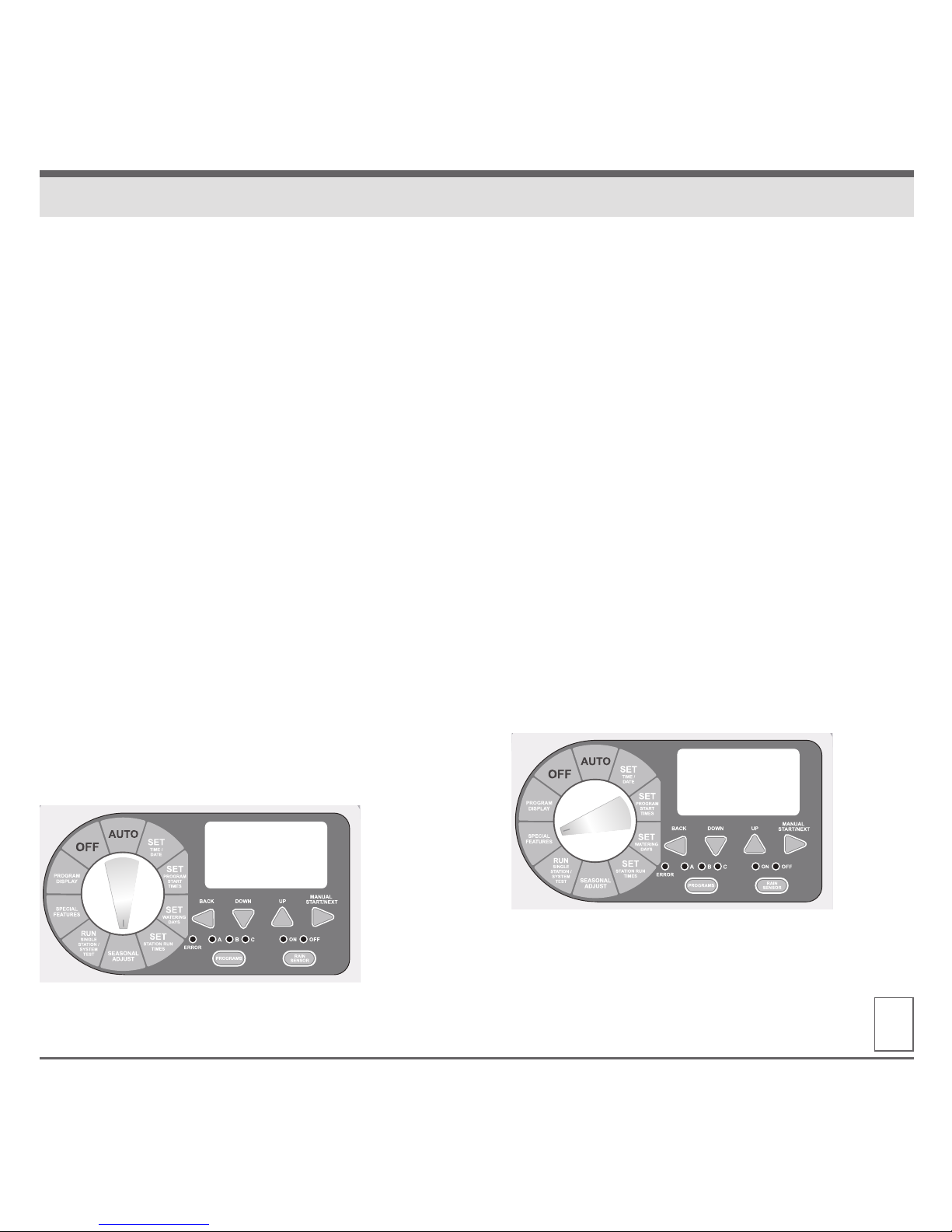
1. Turn the dial to SEASONAL ADJUST. Display
will show “SEASONAL ADJUST % 100.”
2. Press UP or DOWN buttons to set the
percentage in 10 degree increments.
3. Return the dial to AUTO.
STATION DELAY/OVERLAP
The station delay / overlap feature allows the user
to insert a global time delay or overlap between
the end of any station’s watering cycle and the
beginning of the next station’s watering cycle.
Station delay is used in systems that have slow
closing valves or pump systems operating with
a slow recovery time.
Station overlap is used to reduce hydraulic
overload (water hammer).
1. Turn the dial to SPECIAL FEATURES. Display
will show “DELAY 0:00.”
2. Press the UP button to add a delay time. Delay
times can be set from 1 second up to 9 hours.
3. Press DOWN button to add an overlap time.
Overlap times can be set from 1 to 9 seconds.
4. Return the dial to AUTO.
12
SPECIAL FEATURES
100
seasonal adj. %
0:00
MINUTES SECONDS
DELay
Page 14
www.krain.com
PUMP ON / OFF
The PUMP ON/OFF feature allows the user to enable
or disable the MV/PS terminal for each individual
station.
The ON/OFF feature is used in irrigation systems
where it is desirable for a pump to operate or not
operate for a specific station(s).
1. Turn the dial to SPECIAL FEATURES. Display will
show “DELAY 0:00.”
2. Press NEXT button until “PUMP” is displayed.
3. Press the BACK and NEXT buttons simultaneously
to enter the PUMP ON/OFF feature. The display will
show “PUMP ON” and all stations.
4. Press BACK or NEXT to select desired station.
5. Press UP or DOWN buttons to activate (ON) or
deactivate (OFF) the station.
6. Return the dial to AUTO.
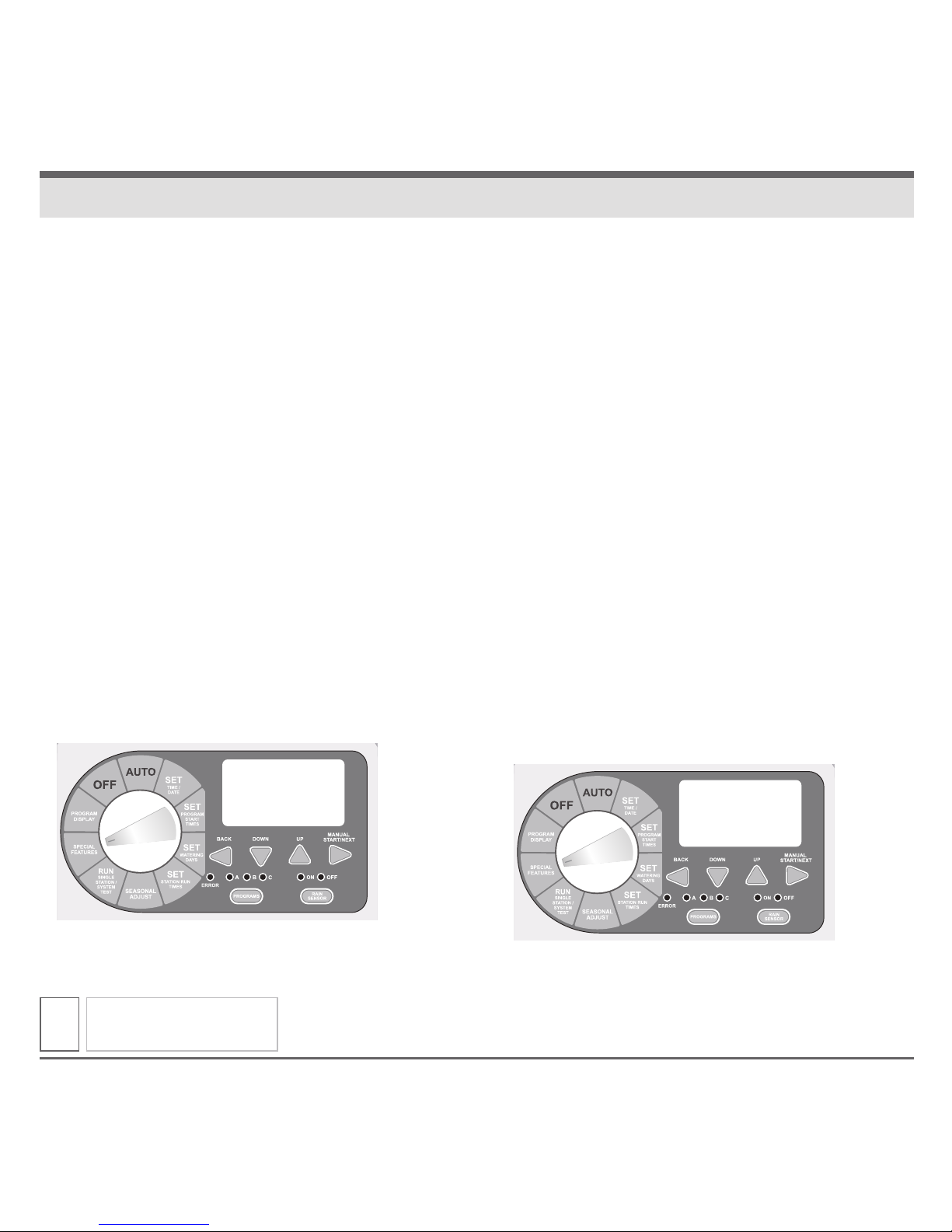
SENSOR
The SENSOR ON/OFF feature allows the user
to enable or disable the SENSOR terminals for
each individual station.
The on/off feature is used in irrigation systems
where it is desirable for a Rain Sensor to operate
or not operate for a specific station(s).
1. Turn the dial to SPECIAL FEATURES. Display
will show “DELAY 0:00.”
2. Press NEXT button until “SENSOR” is displayed.
3. Press the BACK and NEXT button simultaneously
to enter the sensor on / off feature. The display
will show “ACTIVE” and all stations.
4. Press the BACK or NEXT buttons to select
desired station.
5. Press the UP or DOWN buttons to activate
(ON) or bypass (OFF) the station.
6. Return the dial to AUTO.
SPECIAL FEATURES
13
Pump
SENSOR
Page 15
CLEAR
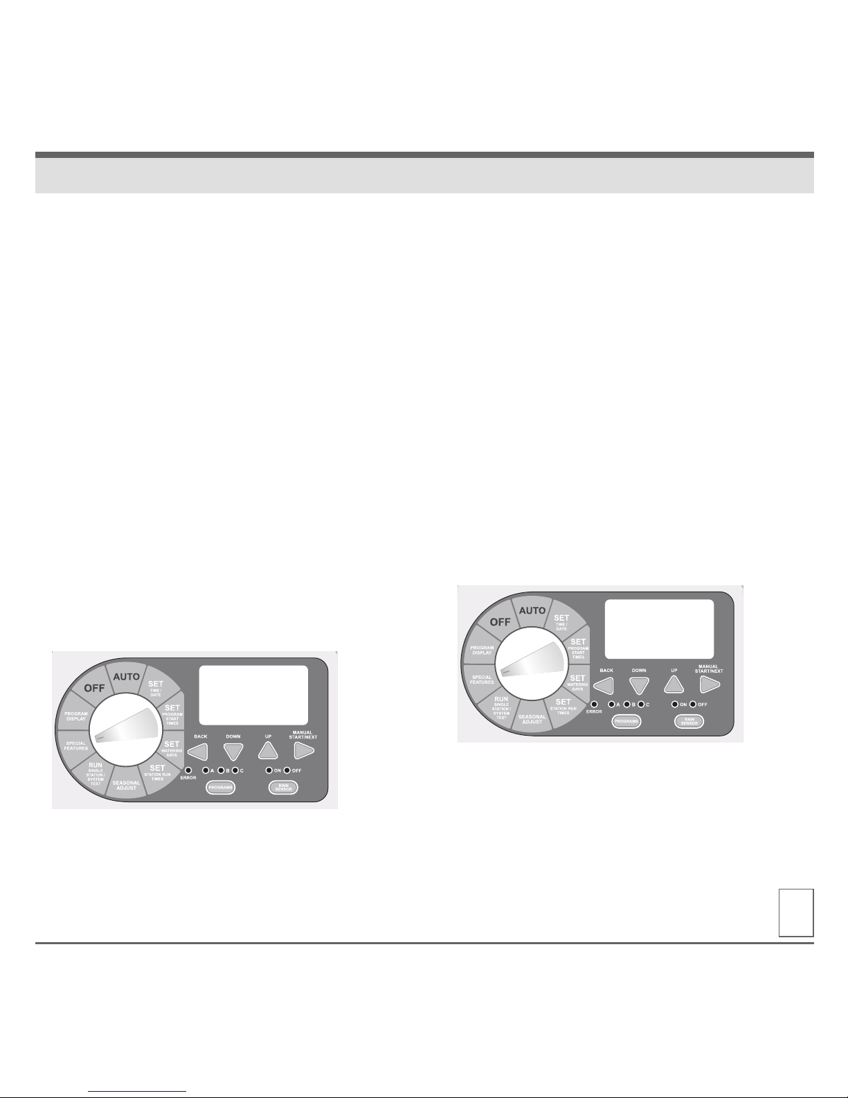
The CLEAR feature allows the user to erase
all current programing and restore the original
factory default program (all available stations,
everyday for ten minutes).
1. Turn the dial to SPECIAL FEATURES.
The display will show “DELAY 0:00.”
2. Press the NEXT button until “CLEAR”
is displayed.
3. To enter the CLEAR feature press the UP
or DOWN button and the display should
now show “CLEAR*.”
4. Press the NEXT button to clear the current
program. The display will briefly show
“CLEARED” before automatically advancing
to the next available feature.
5. Return the dial to AUTO.
SAVE
The SAVE feature allows the user to save all
current programing. This allows the user to quickly
and easily restore any saved program(s) should
they be changed.
1. Turn the dial to SPECIAL FEATURES. Display will
show “DELAY 0:00.”
2. Press the NEXT button until “SAVE” is displayed.
3. To enter the SAVE feature press the UP or DOWN
button and the display should now show “SAVE*.”
4. Press NEXT button to save the current program(s).
Display will briefly show “SAVED” before automatically advancing to the next available feature.
5. Return the dial to AUTO.
14
SPECIAL FEATURES
CLEAR
SAVE
Page 16
www.krain.com
RESTORE
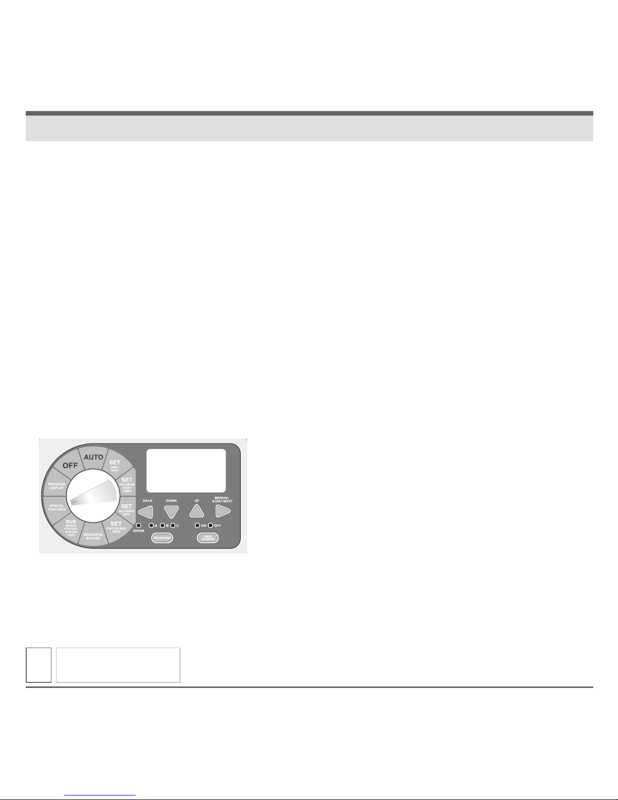
The “RESTORE” feature allows the user to
restore any previously saved programs.
1. Turn the dial to SPECIAL FEATURES.
Display will show “DELAY 0:00.”
2. Press the NEXT button until “RESTORE”
is displayed.
3. To enter the RESTORE feature press the UP
or DOWN button and the display should now
show “RESTORE.”
4. Press the NEXT button to restore any
previously SAVED program(s). Display will
briefly show “RESTORD” before automatically
advancing to the next available feature.
5. Return the dial to AUTO.
SPECIAL FEATURES
15
RESTORE
Page 17
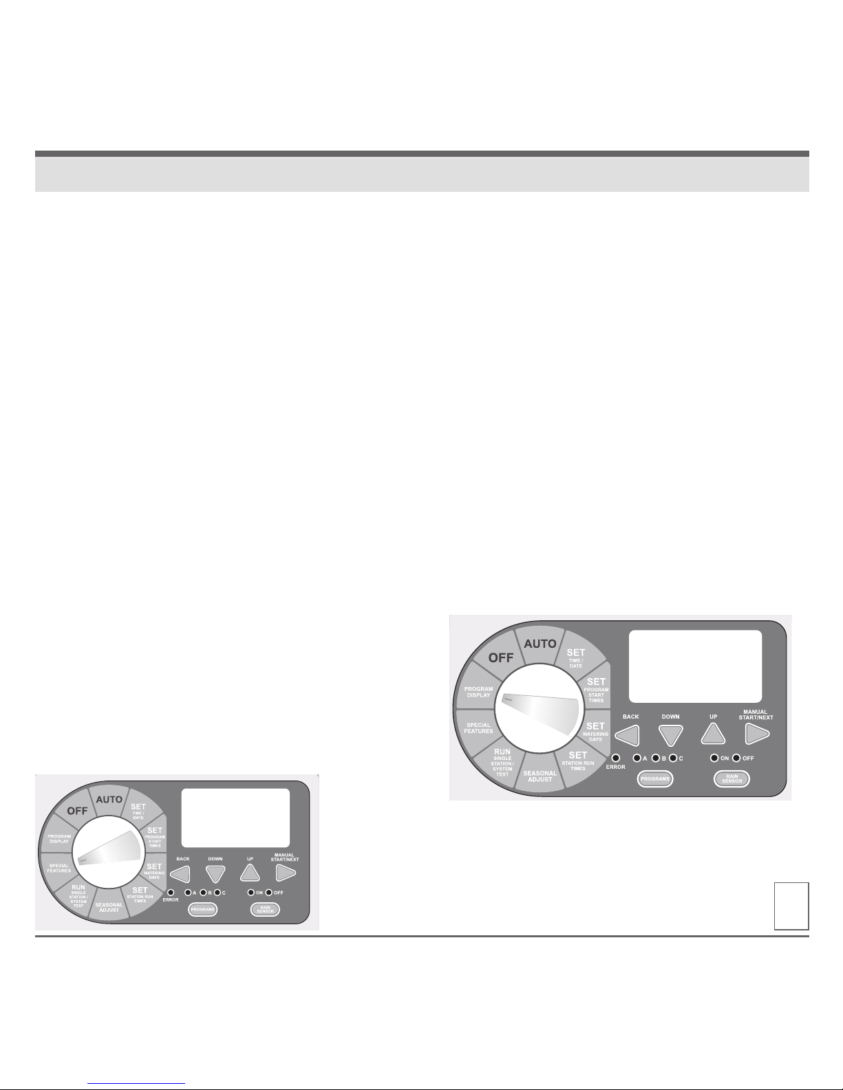
Permanent days off programmed through special
features will not display on program features OR in
the smartphone/tablet interface
Some users or water conservation programs
may desire that a specific day(s) of the week be
prohibited from watering. The DAY OFF feature
allows the user to select a day or days of the week
where the system will not operate regardless of
SET WATERING DAYS program.
1. Turn the dial to SPECIAL FEATURES. Display
will show “DELAY 0:00.”
2. Press the NEXT button until “DAY OFF” is
displayed and a flashing “MON” in the upper
left corner of the LCD.
3. Press the UP or DOWN buttons to enable (turn
on) the day off feature. The display will now
show a solid (non-flashing) “MON.”
4. Press NEXT to advance to next day of the week.
5. Repeat steps 3 and 4 until all non-watering days
have been selected.
6. Return the dial to AUTO.
NOTE: All days visible at the top of the display will
become non-watering days regardless of programming.
The Pro-LC program display feature
provides a complete visual overview of
any program contents.
From this one screen the user can see all
programmed Watering Days, the number
of Watering Start Times and Stations with
a run time per each individual program.
1. Turn the Dial to PROGRAM DISPLAY.
2. Use the Program Switch to select the
program (A, B or C) you wish to review.
3. If more than one start time has been set
(maximum of four), they will appear next
to “START TIME” on the display.
4. Press the NEXT button to view any
additional start times.
5. Return the dial to AUTO.
16
DAY OFF PROGRAM DISPLAY
DAY OFF
mon
1st 8:00
aM
mon tue wed thu fr sat sun
a
pgm
start time 1
station 1 2 3 4
Page 18

www.krain.com
The Pro-LC controller can be installed
either indoors or outdoors and must be done
in compliance with local electrical codes.
For the best viewing and ease of programming
we recommend installation at eye level.
The mounting location should have access
to 115VAC or 220VAC electrical power and allow
enough bottom clearance for the installation of
conduit or a “junction” box if required.
Installation should be done at least 15 feet
away from a pump start relay or any high
draw motors, such as air conditioners and
refrigerators.
For ease of installation the enclosure door
and main panel can be removed. 12 inches
of horizontal clearance to the left is necessary
to fully open the hinged door.
1. Open the enclosure door and swing it to the
left until fully open.
2. Using both hands grasp both the top and
bottom portions of the door at the hinge
location.
3. Gently pull either the top or bottom portion
of the door forward until the door releases.
INSTALLATION DOOR REMOVAL
17
Page 19
18
MOUNTING THE CONTROLLER FIELD WIRE ENTRANCES
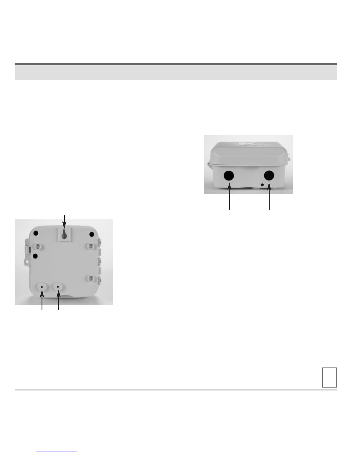
The Pro-LC has a single keyhole slot on the top /
back of the controller. Two circular mounting holes
are located at the bottom / back of the controller.
Use a pencil to mark the eye level position on the
mounting wall. Or, use the template provided for
easy installation.
Drive an appropriate fastening device for the type
of wall material into the mark for the keyhole.
Hang the controller on the keyhole slot making sure
the fastener is secured on the narrow neck area of
the keyhole slot.
Making sure the controller is level, drive an
appropriate fastener(s) in the lower circular hole(s).
The Pro-LC controller has two plugs available
for the routing valve, pump start and sensor wires.
Both are located on the bottom of the cabinet
and sized to 1/2” and 3/4” PVC male adapters.
KEYHOLE SLOT
MOUNTING HOLES
PLUGS
Page 20
www.krain.com19
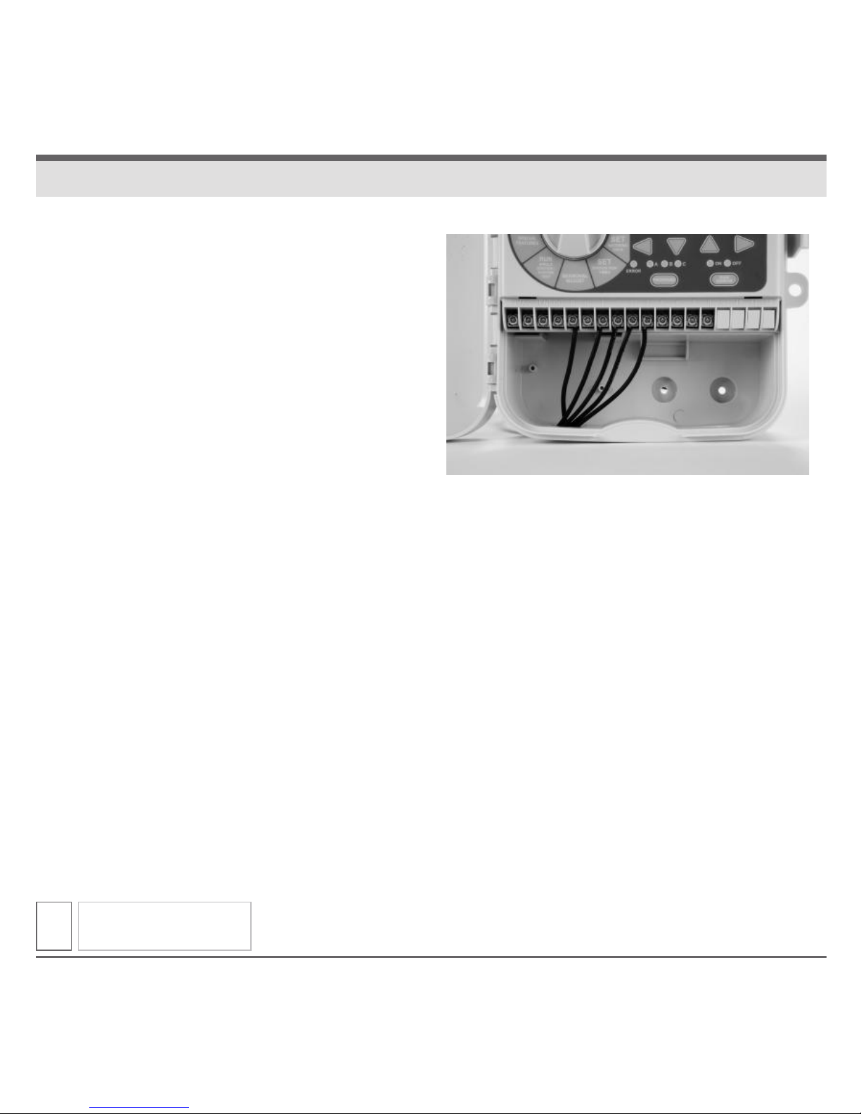
1. Connect each valve with its individual power
wire to one of the numbered screw terminals.
Station numbers are engraved in the mid-box
with the following numbering: 1, 2, 3, 4, 5, 6, 7,
8, 9, 10, 11 and 12.
2. Connect the common field wire from all valves
to the terminal screw located at the left side
between the Sensor and “P” (Pump) terminal
screws.
3. Only use code approved wiring for underground
installation.
CONNECTING VALVE WIRES
Page 21
20
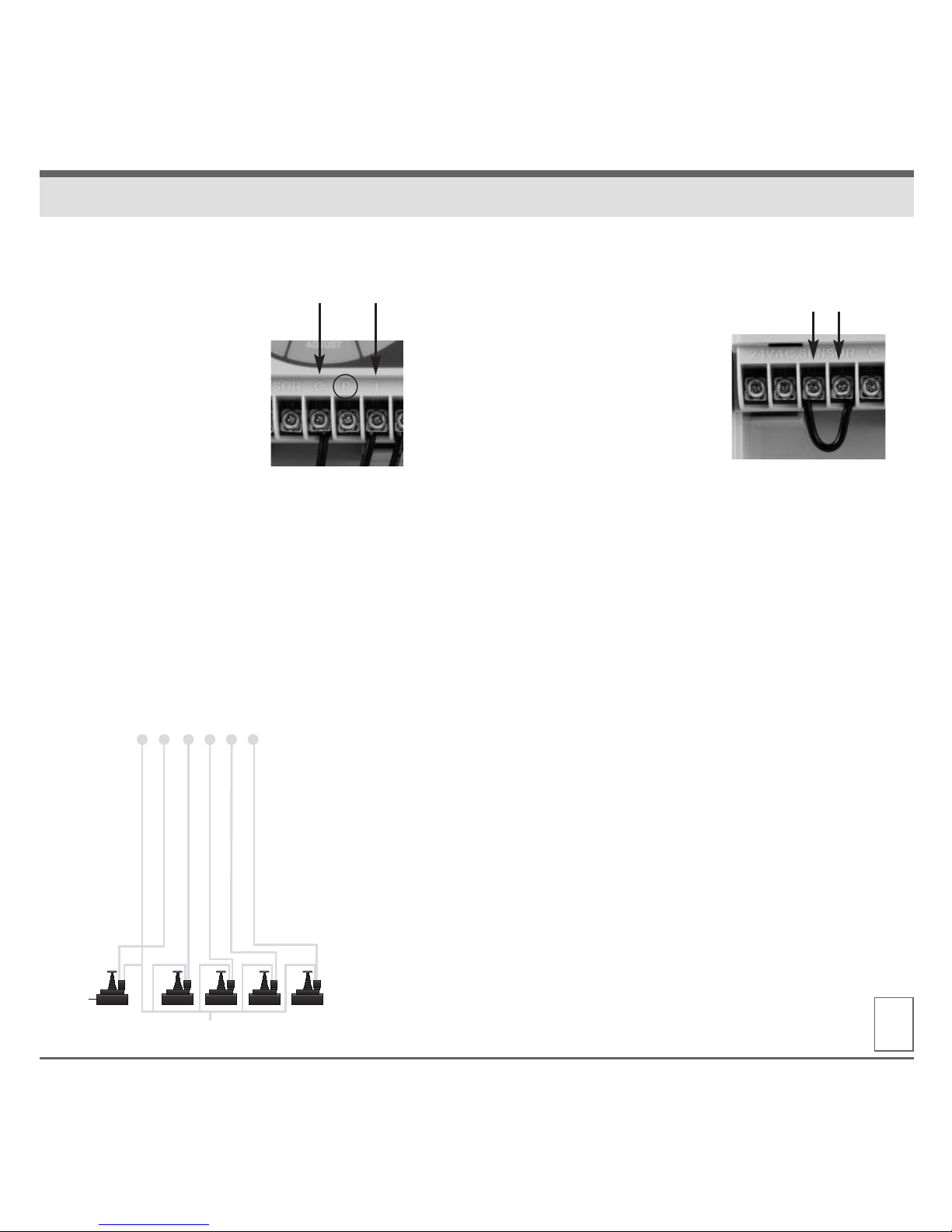
This section is only for systems that require a
pump start relay. The controller does not provide
main power for a pump.
Pump Start Relay
wiring terminal is
located between “C”
and ”1” screw terminals.
NOTE: JUMPERS FOR
UNUSED STATIONS
To prevent pump or system damage when using
a pump start relay, use a jumper to connect all
unused stations to the last station with a run time.
Unused station(s) without a jumper could cause
pump or system damage should the unused
station be turned on. Pump operation with no
flow (dead-head), could cause over-pressurization
of the system or the pump to overheat.
All electrical connections and wiring must
be made according to local building codes.
1. Open the cabinet door.
2. Connect the two
rain sensor wires
to the two terminals
marked SENSOR
located at #3 and
#4 screw terminals.
NOTE:
If a rain sensor has not been installed
in the Pro-LC, the preinstalled jumper wire
must remain installed on the SENSOR terminals.
PUMP START RELAY
RAIN SENSOR INSTALLATION
VALVE COMMON WIRE
MASTER
VALV E
VALV E
WIRES
Page 22
www.krain.com
POWERING THE CONTROLLER
21
It is recommended that a licensed electrician
perform the following power installation.
All electrical connections and wiring must
be made according to local building codes.
Make sure all electrical power is turned off
before any wire connections are attempted.
For ease of installation the enclosure door
can be removed. Please refer to the installation
instructions on page 17 for door removal.
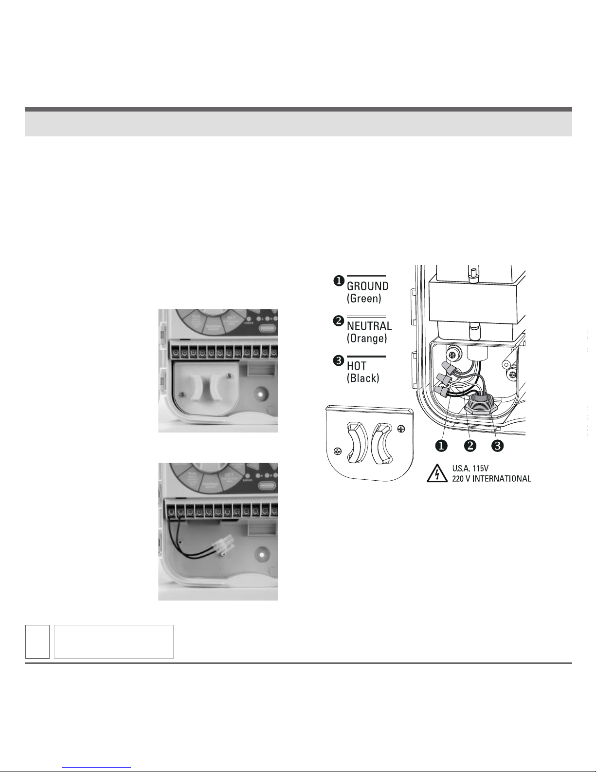
FOR OUTDOOR
CONTROLLER ONLY:
The hole located on
bottom left side of the
cabinet should be
used to bring AC power
wires and conduit into
the power junction box.
FOR INDOOR
CONTROLLER ONLY:
Pro-LC is powered with
either 115VAC or 220VAC
which must be noted
when ordering the unit.
Installation is easy.
Simply plug connector
from the controller with
the connector on the
end of the plug pack.
The Pro-LC controller is powered with either
115VAC or 220VAC which must be noted when
ordering the unit.
Connect the AC wires to the transformer wires
located inside the power junction box with wire
nuts or other locally approved connectors.
s
!
WARNING: Risk of explosion. Potential risk if
battery is replaced with an incorrect type.
The battery must be removed and disposed
of properly.
Page 23

OPERATING SPECIFICATIONS
• Station Run Times:
1 second to 6 hours on
programs A, B and C.
• Start Times: 4 per program
(12 maximum per day).
• Watering Schedule:
7-day calendar (any day of the week),
odd or even calendar day,
interval watering up to 31 days.
• Operating Temperature:
0-140° F (18-60° C)
DIMENSIONS
• Height: 7"
• Width: 7.4”
• Depth: 3.7”
ELECTRICAL SPECIFICATIONS
• Transformer Input:
115VAC, 60Hz or 220 VAC, 50/60Hz
• Transformer Output:
Outdoor Unit: 24VAC, 1 amp
Indoor Unit: 24VAC, 1 amp
• Maximum Output:
Outdoor Unit: 24VAC, 0.75 amp
Indoor Unit: 24VAC, 0.75 amp
(includes Master Valve/Pump Start)
• For PERMANENTLY CONNECTED
EQUIPMENT, a readily accessible
disconnect device shall be
incorporated external to the equipment.
DEFAULT SETTINGS
The Pro-LC controller has a battery
backup used for time and calendar
accuracy during power outages.
22
SPECIFICATIONS
Page 24
www.krain.com
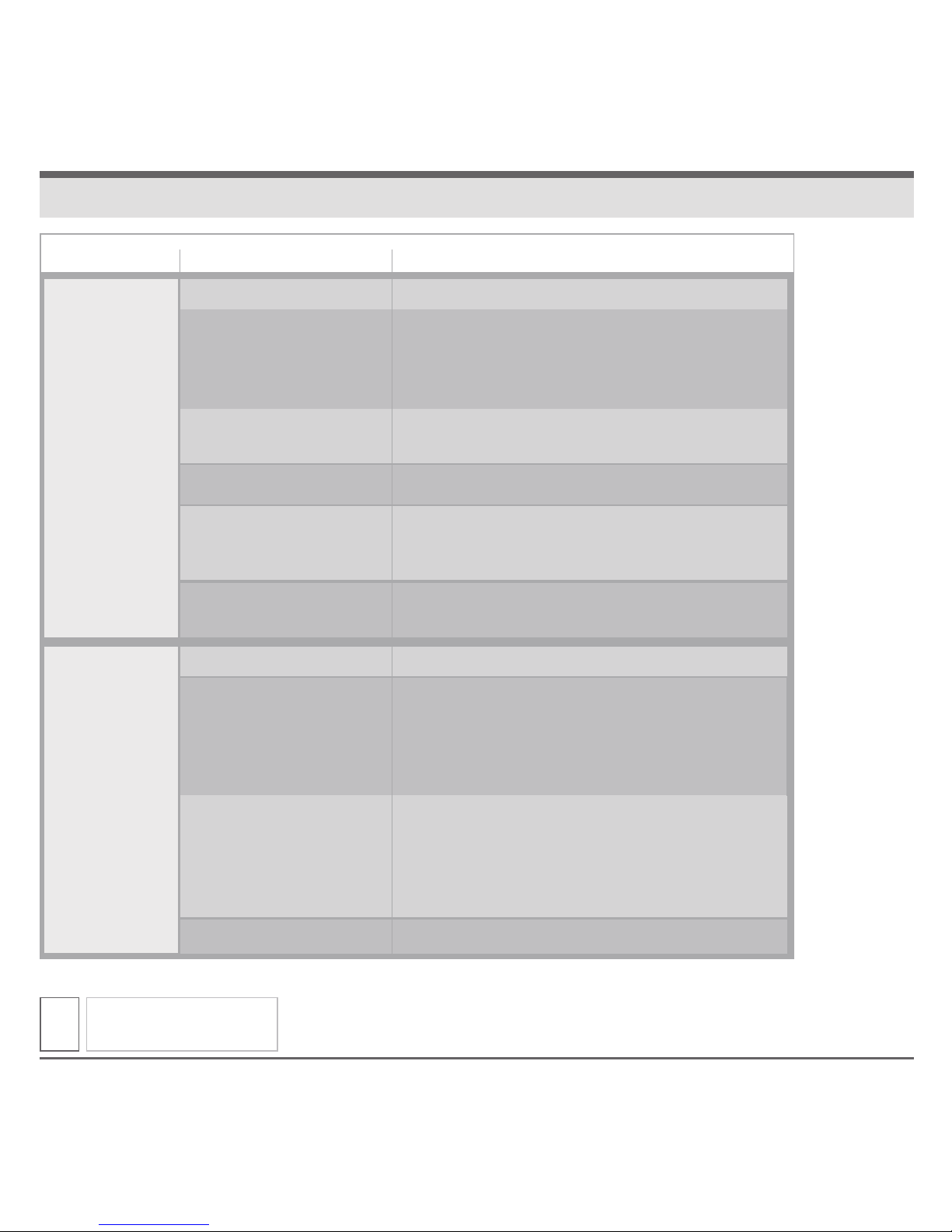
TROUBLESHOOTING
23
PROGRAM
DOES NOT
COME ON
AUTOMATICALLY
DISPLAY SHOWS
A STATION IN
OPERATION BUT
NO WATERING
OCCURS
Dial set to the OFF position
No Start Time
Permanent Day Off
Feature is Active
No Primary AC Power
Today may not be a
Scheduled Watering Day
Active or Faulty Rain Sensor
No Primary AC Power
An Open Circuit in the Valve
Solenoid or Wiring has
disabled the station (Open
Circuit Feature has been
disabled – page 12)
Rain Sensor is Active and
preventing watering
Sensor Jumper is missing
Set dial to AUTO
Turn the dial to PROGRAM DISPLAY check
program for start time(s). If missing turn dial
to SET PROGRAM START TIMES and enter
a start time(s) if needed (page 5).
Change permanent day programming
if needed (page 14).
Restore primary AC power.
Turn the dial to PROGRAM DISPLAY and check program
Watering Day(s). If missing turn the dial to SET WATERING
DAYS and enter watering day(s) if needed (page 6).
Check LCD Display for BYPASSED or SENSOR.
Set Rain Sensor Switch to the Bypassed position.
Restore primary AC power.
Locate and repair.
Turning ON the Open Circuit Feature will prevent
station operation when the valve solenoid or wiring
has disabled the station (page 12).
If a recent rain event has occurred
then no action is required.
Place Rain Sensor Switch in the BY PASSED position
to resume operation. If watering does not resume the
Rain Sensor is not operating properly.
Replace Jumper
SYMPTOM POSSIBLE CAUSE CORRECTION
Page 25
24
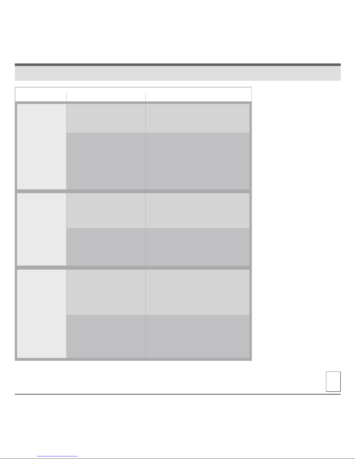
TROUBLESHOOTING
SYMPTOM POSSIBLE CAUSE CORRECTION
STATION(S)
DOES NOT
COME ON
DISPLAY IS
PARTIALLY OR
COMPLETELY
BLANK
STATION(S)
REPEAT
OPERATION
Turn the Dial to SET STATION RUN
TIMES and check program station
for run time.
Locate and repair SHORT/ OPEN circuit.
Error Tone, LED and Display will flash
showing affected station(s). To
temporarily clear the alarm, turn Dial
to OFF position briefly and return Dial
to AUTO. Controller will auto reset after
repair has been performed.
Check for properly installed
electrical installation.
Check for tripped electrical
Breakers or fuses.
Perform a controller RESET. If no
permanent damage occurred the
controller will accept programing
commands and function normally.
Turn the dial to PROGRAM DISPLAY
and check program(s) for additional
start time(s). If unwanted start times
are present turn dial to SET PROGRAM
START TIMES and remove (page 5).
Programs stack when another
program start time occurs while
another program is still running.
Check all programs (A, B and C)
and start times (4 per each program).
No Station Run Time has
been set
A SHORT or OPEN circuit has
disabled station operation
Loss of primary AC power
An electrical surge or strike
has damaged the electronics
More than one (1) start time
has been programmed
The programs could
be stacked
Page 26
www.krain.com
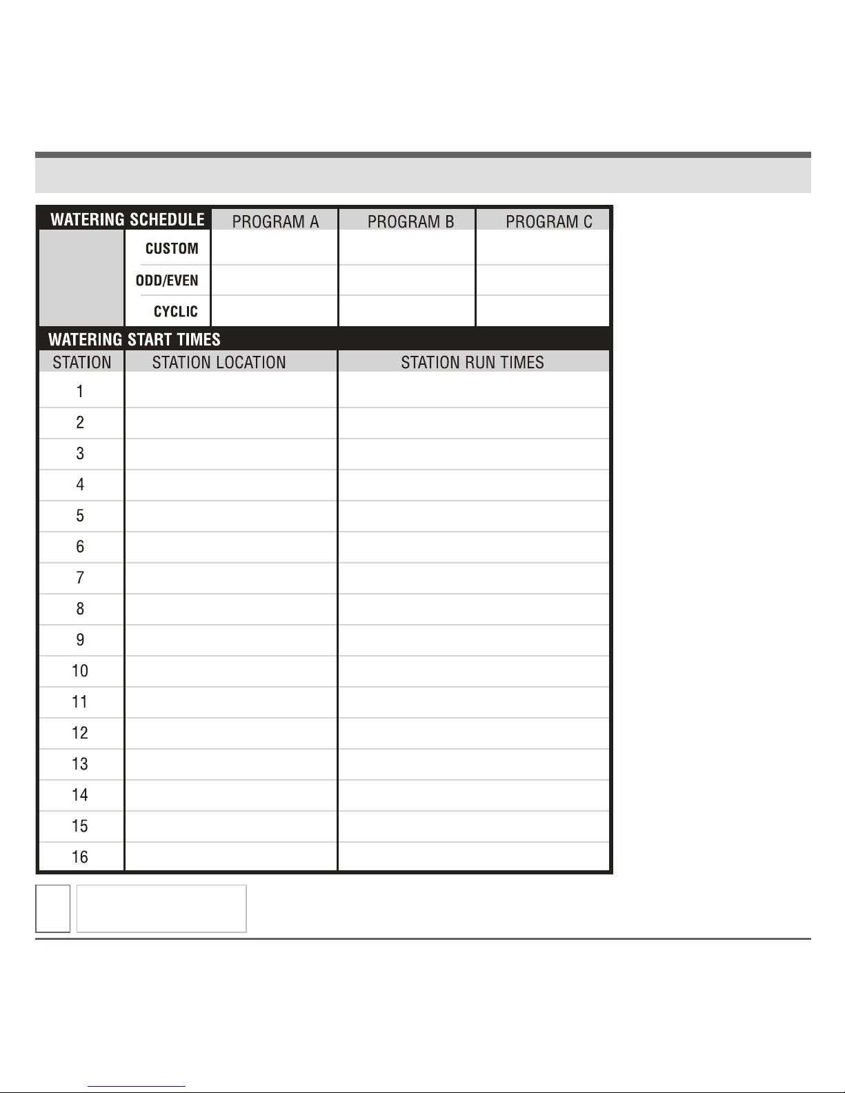
SPARE WATERING PLANNER
25
Page 27
26
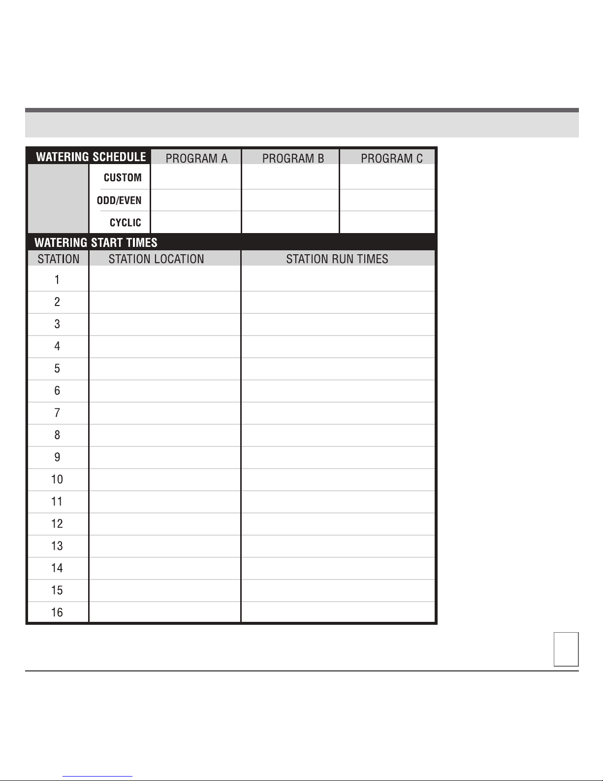
SPARE WATERING PLANNER
Page 28

The manufacturer guarantees to the original purchaser
that any product supplied by the manufacturer will be free
from defects in material and workmanship for a period of
two years from the date of purchase. Any product found
to have defects in material or workmanship within the
warranty period shall be repaired or replaced by the
manufacturer.
The manufacturer does not guarantee the use for a
particular purpose of its products and does not make any
guarantee, expressed or implied, other than the warranty
contained herein. The manufacturer shall not be liable
for any loss from use of the product or incidental or
consequential damages to other parts of any installation
of which this product is part.
The warranty shall not apply to any equipment which is
found to have been improperly installed, set up or used in
any way not in accordance with the instructions supplied
with this equipment, or to have been modified, repaired
or altered in any way without the expressed consent of
the manufacturer. This warranty shall not apply to any
batteries or accessories used in the equipment covered
under this warranty or to any damage which may be
caused by such batteries.
If the controller develops a fault, the product or main
panel must be returned in adequate packing with:
1. a copy of your original invoice;
2. a description of any fault; and
3. contact name and information.
It is the purchasers responsibility to return the controller
to the manufacture or their agent by prepaid freight.
WARRANTY
K-Rain Manufacturing Corp.
ATTN: WARRANTY
1640 Australian Avenue
Riviera Beach, FL 33404
(561) 844-1002
(561) 842-9493 FAX
(800) 735-7246 / www.krain.com
© K-Rain Manufacturing Corp.
AN ISO 9001 CERTIFIED COMPANY 26007201
Manufacturing Corporation
Modular Irrigation Sprinkler Controller
Hereby, K-Rain Manufacturing Corporation declares that this
irrigation controller Pro LC is in compliance with the essential
requirements and other provisions of Directive 1999/5/EC.
IP 24 Certified
Certificate of Conformity
to European Directives
 Loading...