

Page 1
ProSport™ Gear Driven Sprinkler Setting Instructions
NOTE: The ProSport is factory preset with a 180° arc setting, and includes a pre-installed #10 nozzle.
CHANGING A NOZZLE
s
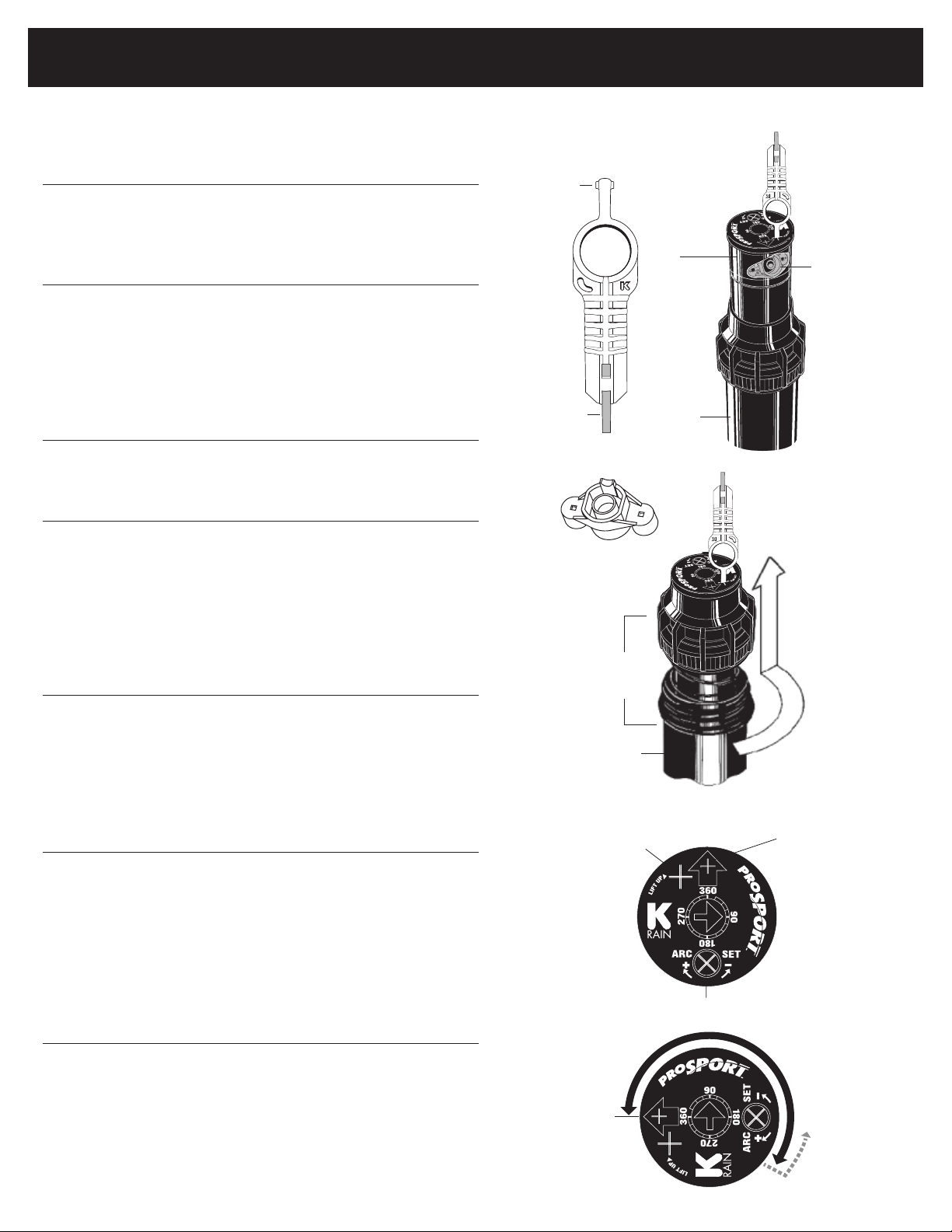
REMOVING THE NOZZLE RETENTION SCREW
1
Use the (B) end of the key to remove the nozzle retention
screw (L) by turning counter-clockwise to remove and
clockwise to re-install.
s
PULL UP THE RISER
2
Insert the (A) end of the key in the keyhole (J) on the top
of the nozzle turret (D) and turn the key 1/4 turn to insure
that the key does not slip out of the keyhole when you
pull it up. Firmly pull up the entire spring-loaded riser to
access the nozzle socket (E). Hold the riser assembly up
with one hand.
s
REMOVING THE NOZZLE
3
Using a pair of needle-nose pliers, grasp the nozzle
on the side of the outer ring and pull the nozzle out.
s
4
INSTALLING A NOZZLE
Press desired nozzle into the nozzle socket. Make sure
the nozzle number is visible and the nozzle “prongs”
are up. Then, re-install the nozzle retention screw.
NOTE: The nozzle retention screw is also a break-up
screw and used to adjust the distance of the spray.
A
B
G Nozzle
Key
C Key in Keyhole
D
Nozzle
Turret
F
Can
E Nozzle
Socket
H Key in Keyhole
SETTING THE ARC ADJUSTMENT
s
FINDING THE LEFT START POSITION
1
Place your ngers on the top center of the nozzle turret.
Rotate the turret to the right until it stops and then back
to the left until it stops. Notice the position of the nozzle
arrow. This is the “Left Start” position. The sprinkler will
begin spraying from this position and rotate clockwise
until it reaches the right Adjustable Stop-Return Point.
s
ORIENTING THE LEFT START POSITION
2
Insert the (A) end of the key in the keyhole (J) on the top
of the nozzle turret (D) and turn the key 1/4 turn to insure
that the key does not slip out of the keyhole when you pull
it up. Being careful not to allow the nozzle turret to turn,
rmly pull up the entire spring-loaded riser. Hold the lower
riser assembly up with one hand. Now turn only the lower
riser clockwise or counter-clockwise until the nozzle arrow
is pointing where you want the sprinkler to begin spraying.
s
CHANGING THE ARC
3
Insert end of the key (B) into Arc Set Adjustment slot (M).
Turn clockwise to increase the arc or counter-clockwise
to decrease the arc. NOTE: The arc set arrow in the center
of the nozzle turret rotates to show the current setting.
WHEN SET AT 360°, THE PROSPORT WILL ROTATE
CONTINUOUSLY IN A CLOCKWISE DIRECTION.
I Sprinkler
Assembly
J Keyhole
Left
Start
F
Can
K Nozzle Turret
M Arc Set Adjustment
L Nozzle
Retention
Screw
Adjustable
stop-return point
Page 2
ProSport™ Gear Driven Sprinkler Setting Instructions
SPRINKLER INSTALLATION
s
INSTALL AND BURY
1
Do not use pipe dope. Thread the sprinkler on the pipe. Bury the
sprinkler ush to grade. NOTE: Gear driven sprinklers and pop-up
sprays should not be installed on the same watering zone.
s
INSPECTING THE FILTER
2
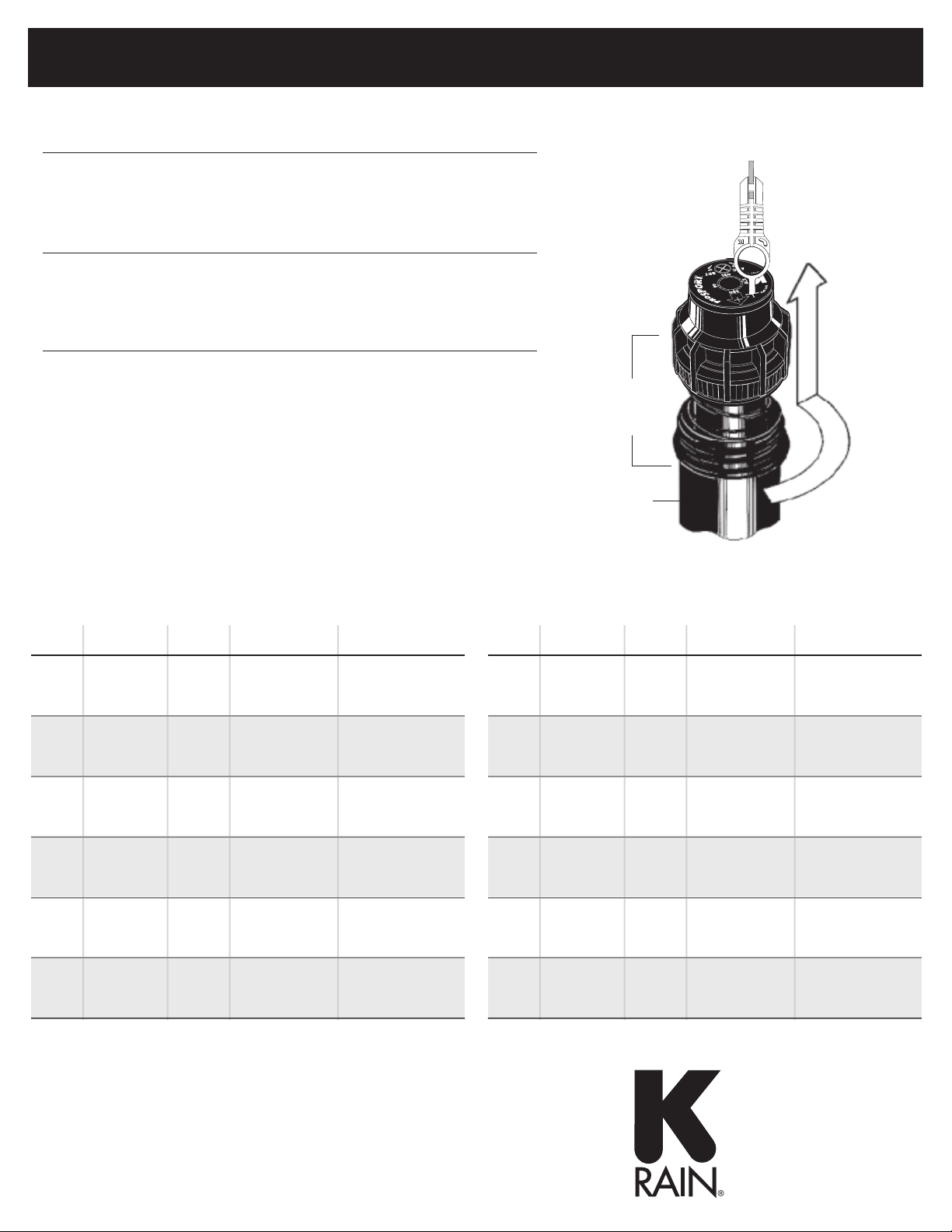
Unscrew the top and lift the complete sprinkler assembly (I) out of
the housing can. The lter is located on the bottom of the sprinkler
assembly and can easily be pulled out, cleaned and re-installed.
s
3
WINTERIZATION TIPS
When using an air compressor to remove water from the system
please note the following:
a. Do not exceed 30 PSI.
b. Always introduce air into the system gradually to avoid air
pressure surges. Sudden release of compressed air into the
sprinkler can cause damage.
c. Each zone should run no longer than 1 minute on air. Sprinklers
turn 10 to 12 time faster on air than on water. Over spinning
rotors on air can cause damage to the internal components.
I Sprinkler
Assembly
F
Can
H Key in Keyhole
PERFORMANCE DATA - MODEL 14003
NOZZLE PRESSURE RADIUS FLOW RATE PRECIP in/hr / mm/hr
PSI kPa Bars Ft. M. GPM L/M M
#5 40 276 2.8 45' 13.7 5.1 19.3 1.2 0.48 0.58 12 14
White White
50 345 3.5 47' 14.3 5.9 22.3 1.3 0.51 0.62 13 15
60 414 4.1 47' 14.3 6.5 24.6 1.5 0.57 0.68 14 17
70 483 4.8 49' 14.9 7.1 26.9 1.6 0.57 0.68 15 17
#10 50 345 3.5 53' 16.2 10.6 40.1 2.4 0.73 0.87 18 21
Green Green
60 414 4.1 53' 15.9 11.8 44.7 2.7 0.81 0.97 21 24
70 483 4.8 53' 16.2 12.6 47.7 2.9 0.86 1.04 22 25
Pre-
80 552 5.5 55' 16.8 13.5 51.1 3.1 0.86 1.03 22 25
installed
#15 50 345 3.5 57' 17.4 13.0 49.2 3.0 0.77 0.92 19 23
Gray
60 414 4.1 59' 18.0 14.2 53.8 3.2 0.79 0.94 20 23
70 483 4.8 59' 18.0 15.4 58.3 3.5 0.85 1.02 22 25
80 552 5.5 63' 19.2 16.5 62.5 3.8 0.80 0.96 20 23
#20 60 414 4.1 65' 19.8 18.9 71.5 4.3 0.86 1.03 22 25
Brown Brown
70 483 4.8 67' 20.4 20.5 77.6 4.7 0.88 1.06 22 26
80 552 5.5 69' 21.0 21.9 82.9 5.0 0.89 1.06 23 26
90 621 6.2 71' 21.6 23.2 87.8 5.3 0.89 1.06 23 26
25 60 414 4.1 67' 20.4 22.8 86.3 5.2 0.98 1.17 25 29
Blue Blue
70 483 4.8 71' 21.6 24.8 93.9 5.6 0.95 1.14 24 28
80 552 5.5 75' 22.9 26.5 100.3 6.0 0.91 1.09 23 27
90 621 6.2 77' 23.5 26.8 101.4 6.1 0.87 1.04 22 25
#30 60 414 4.1 67' 20.4 23.7 89.7 5.4 1.02 1.22 26 30
Black Black
70 483 4.8 69' 21.0 25.6 96.9 5.8 1.04 1.24 26 30
80 552 5.5 69' 21.0 27.5 104.1 6.3 1.11 1.33 28 33
90 621 6.2 71' 21.6 29.2 110.5 6.6 1.12 1.34 28 33
*All precipitation rates calculated for 180° operation.
For the precipitation rate for a 360° sprinkler, divide by 2.
3
/H n s n s
PERFORMANCE DATA - MODEL 14053
NOZZLE PRESSURE RADIUS FLOW RATE PRECIP in/hr / mm/hr
PSI kPa Bars Ft. M. GPM L/M M
#5 40 276 2.8 43' 13.1 5.9 22.3 1.3 0.61 0.71 16 18
50 345 3.5 44' 13.4 6.2 23.5 1.4 0.62 0.71 16 18
60 414 4.1 45' 13.7 6.4 24.2 1.5 0.61 0.70 15 18
70 483 4.8 45' 13.7 7.6 28.8 1.7 0.72 0.83 18 21
#10 50 345 3.5 49' 14.9 10.6 40.1 2.4 0.85 098 22 25
60 414 4.1 53' 15.8 11.5 44.3 2.7 0.79 0.91 21 25
70 483 4.8 53' 16.1 13.3 50.3 3.0 0.91 1.05 23 27
Pre-
80 552 5.5 54' 16.5 14.0 53.0 3.2 0.92 1.07 23 27
installed
#15 50 345 3.5 52' 15.8 12.4 46.9 2.8 0.88 1.02 23 26
60 414 4.1 54' 16.5 13.6 55.3 3.3 0.90 1.04 24 28
70 483 4.8 56' 17.1 14.6 58.7 3.5 0.90 1.03 24 28
80 552 5.5 58' 17.1 15.9 60.2 3.6 0.91 1.05 23 27
#20 60 414 4.1 56' 17.1 19.8 66.2 4.0 1.22 1.40 27 31
70 483 4.8 58' 17.7 21.2 71.5 4.3 1.21 1.40 27 32
80 552 5.5 59' 18.0 22.8 78.7 4.7 1.26 1.46 29 34
90 621 6.2 60' 18.3 24.4 82.1 4.9 1.30 1.51 29 34
25 60 414 4.1 59' 18.0 22.4 84.8 5.1 1.24 1.43 31 36
70 483 4.8 66' 20.1 25.7 97.3 5.8 1.14 1.31 29 33
80 552 5.5 67' 20.4 27.8 105.2 6.3 1.19 1.38 30 35
90 621 6.2 68' 20.7 29.9 113.2 6.8 1.24 1.44 32 37
#30 60 414 4.1 60' 18.3 25.2 95.4 5.7 1.35 1.56 34 39
70 483 4.8 72' 22.0 28.5 107.9 6.5 1.06 1.22 27 31
80 552 5.5 73' 22.2 30.8 116.6 7.0 1.11 1.28 28 33
90 621 6.2 75' 22.9 32.5 123.0 7.4 1.11 1.28 28 33
3
/H n s n s
K-RAIN MANUFACTURING CORP.
1640 Australian Avenue
Riviera Beach, FL 33404 USA
PH: 561.844.1002 / 1.800.735.7246
FAX: 561.842.9493
www.krain.com
© K-RAIN Manufacturing Corp.
Part Number: 14005103 Rev. 15
 Loading...