

Kraft Powercon PRM1, PRM1 24/80, PRM1 24/240, PRM1 48/100, PRM1 48/200 Series Manual
...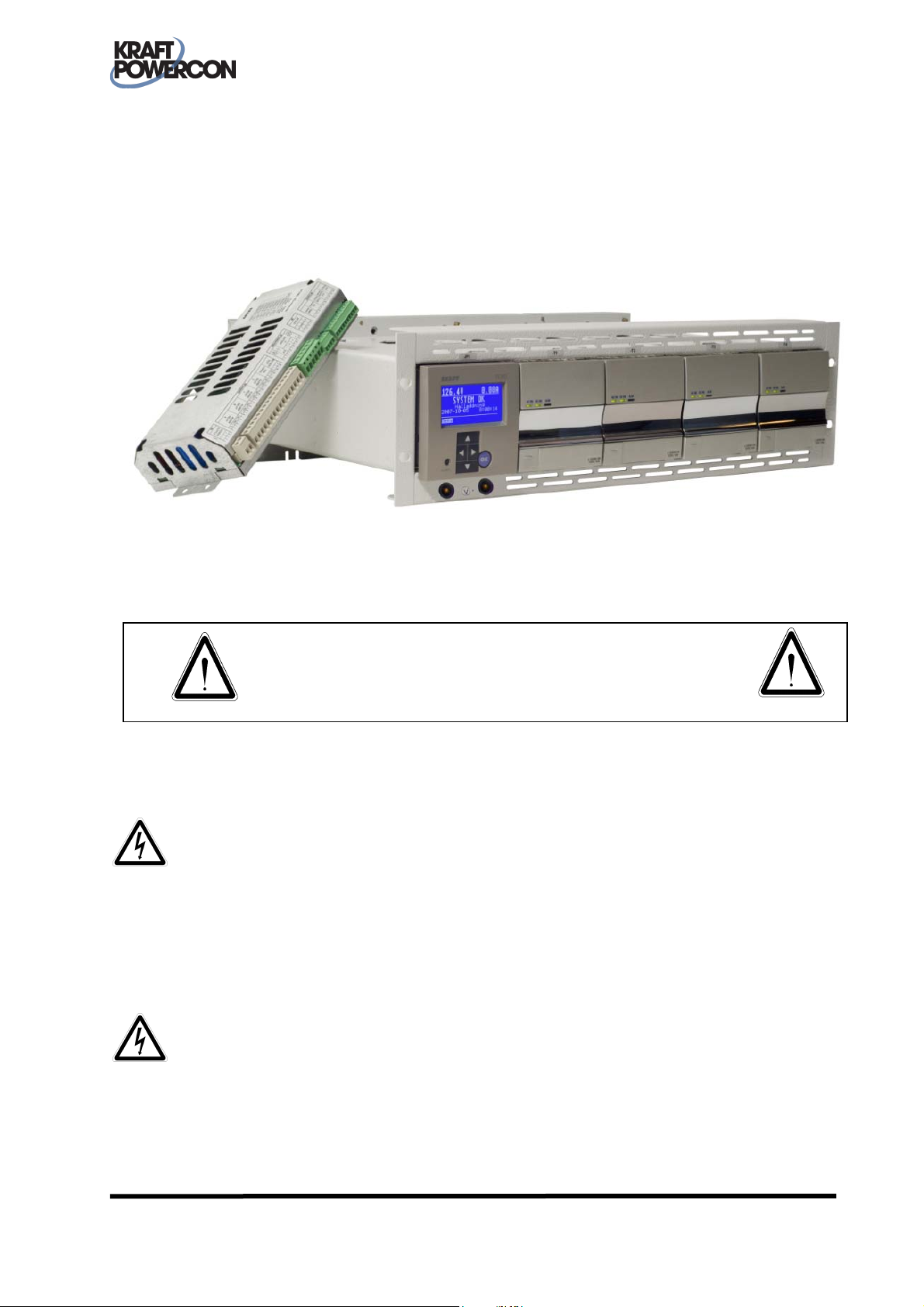
charging rectifier
Manual for
type PRM1
You must read this manual before installation, use or work on the product.
This product contains dangerous voltages that when touched can cause electric shock, burns or
death.
The product must be installed by qualified personnel and according to the installation instructions.
Service may only be performed by authorized service personnel. The equipment housing may only
be removed by authorised personnel when all power has been cut to the equipment for at least
five minutes. The protective covers and contact safety devices inside the equipment may only be
removed by authorised service personnel.
The power must always be disconnected in a safe way before starting any service/maintenance.
Warning for reverse voltage. Power is supplied from several sources.
SAFETY INSTRUCTIONS
Manual: 9-1627-B
P/n: 0001079
KraftPowercon Sweden AB, Hjalmar Petris väg 49, S-352 46 Växjö, Sweden, Tel: +46 470-705200, Fax: +46 470-705201,
www.kraftpowercon.com

2
We reserve the right to make changes to the content of this manual without prior notification.
KraftPowercon Sweden AB, Hjalmar Petris väg 49, S-352 46 Växjö, Sweden, Tel: +46 470-705200, Fax: +46 470-705201,
www.kraftpowercon.com

3
CONTENTS
1 PRESENTATION...................................................................................... 5
2 SAFETY INSTRUCTIONS......................................................................... 6
3 TECHNICAL DATA ................................................................................. 7
3.1 ELECTRICAL DATA ...................................................................................................................... 7
3.1.1 Assortment............................................................................................................................... 7
3.1.2 Common electrical input data.................................................................................................. 7
3.1.3 Common electrical output data................................................................................................ 7
3.1.4 Electrical data for rectifier module ........................................................................................... 8
3.2 ENVIRONMENTAL DATA............................................................................................................ 8
3.3 MECHANICAL DATA................................................................................................................... 8
3.3.1 PRM1....................................................................................................................................... 8
3.3.2 PRM1-W.................................................................................................................................. 9
3.4 CONFORMITY WITH STANDARDS ............................................................................................ 9
4 FUNCTIONAL DESCRIPTION............................................................... 10
4.1 GENERAL................................................................................................................................... 10
4.2 APPLICATION EXAMPLE ........................................................................................................... 10
4.3 RECTIFIER MODULES................................................................................................................ 11
4.4 RACK FOR RECTIFIER MODULES AND OPERATOR PANEL..................................................... 11
4.5 TEST CONTACTS....................................................................................................................... 11
4.6 I/O UNIT.................................................................................................................................... 11
4.7 FUNCTIONS.............................................................................................................................. 11
4.7.1 General.................................................................................................................................. 11
4.7.2 Float charging........................................................................................................................ 11
4.7.3 Equalization charging ............................................................................................................ 11
4.7.4 Battery circuit test .................................................................................................................. 12
5 OPERATION ......................................................................................... 13
5.1 GENERAL................................................................................................................................... 13
5.2 OPERATOR PANEL.................................................................................................................... 13
5.3 RECTIFIER MODULES................................................................................................................ 13
5.4 MAINS SUPPLY ......................................................................................................................... 13
5.4.1 PRM1..................................................................................................................................... 13
5.4.2 PRM1-W / PC10 .................................................................................................................... 14
5.5 TEST CONTACTS....................................................................................................................... 14
6 INSTALLATION INSTRUCTIONS.......................................................... 15
6.1 SAFETY INSTRUCTIONS............................................................................................................ 15
6.2 GENERAL................................................................................................................................... 15
6.3 STORAGE AND PROTECTION.................................................................................................. 15
6.4 MOUNTING.............................................................................................................................. 15
6.4.1 General.................................................................................................................................. 15
6.4.2 PRM1..................................................................................................................................... 15
6.4.2.1 Rack.............................................................................................................................. 15
6.4.2.2 I/O Unit ........................................................................................................................ 15
6.4.3 PRM1-W................................................................................................................................ 15
6.4.4 PC10...................................................................................................................................... 16
6.5 ELECTRICAL INSTALLATION..................................................................................................... 16
6.5.1 General.................................................................................................................................. 16
6.5.2 Earthing ................................................................................................................................. 16
6.5.2.1 PRM1............................................................................................................................ 16
6.5.2.2 PRM1-W....................................................................................................................... 16
6.5.2.3 PC10............................................................................................................................. 16
6.5.3 Mains voltage ........................................................................................................................ 16
6.5.3.1 External fuse rating........................................................................................................ 16
KraftPowercon Sweden AB, Hjalmar Petris väg 49, S-352 46 Växjö, Sweden, Tel: +46 470-705200, Fax: +46 470-705201,
www.kraftpowercon.com

4
6.5.3.2 Connection PRM1......................................................................................................... 16
6.5.3.3 Connection PRM1-W /PC10 ......................................................................................... 17
6.5.4 Battery/Load........................................................................................................................... 17
6.5.4.1 General......................................................................................................................... 17
6.5.4.2 PRM1............................................................................................................................ 17
6.5.4.3 PRM1-W....................................................................................................................... 17
6.5.4.4 PC10............................................................................................................................. 17
6.5.5 Rectifier modules................................................................................................................... 17
6.5.6 I/O Unit ................................................................................................................................. 18
6.5.6.1 General......................................................................................................................... 18
6.5.6.2 Communication cable................................................................................................... 18
6.5.6.3 Power supply PRM1...................................................................................................... 18
6.5.6.4 Power supply PRM1-W................................................................................................. 18
6.5.6.5 Power supply PC10....................................................................................................... 18
6.5.7 Operator panel ...................................................................................................................... 18
6.5.8 Test contacts.......................................................................................................................... 19
6.5.8.1 PRM1............................................................................................................................ 19
6.5.8.2 PRM1-W / PC10............................................................................................................ 19
7 STARTING UP ...................................................................................... 20
7.1 SAFETY INSTRUCTIONS............................................................................................................ 20
7.2 PREPARATORY INSPECTION .................................................................................................... 20
7.2.1 General.................................................................................................................................. 20
7.3 POWERING UP ......................................................................................................................... 20
7.3.1 DC......................................................................................................................................... 20
7.3.2 AC ......................................................................................................................................... 20
7.4 CHECKING THE CHARGING VOLTAGE................................................................................... 20
7.5 CHECKING THE SETTINGS ....................................................................................................... 21
7.6 CHECKING THE OUTPUTS....................................................................................................... 21
8 MAINTENANCE.................................................................................... 22
8.1 ANNUAL INSPECTION.............................................................................................................. 22
8.1.1 General.................................................................................................................................. 22
8.1.2 Checking the charging voltage............................................................................................... 22
8.1.3 Checking the cooling capacity............................................................................................... 22
9 FAULT TRACING.................................................................................. 23
9.1 SAFETY INSTRUCTIONS............................................................................................................ 23
9.2 FAULT TRACING ALARMS........................................................................................................ 23
9.3 OTHER FAULT TRACING .......................................................................................................... 23
Appendices
A LAYOUT AND DIMENSION DIAGRAM, PRM1
B CIRCUIT DIAGRAM, PRM1
C LAYOUT AND DIMENSION DIAGRAM, PRM1-W
D CIRCUIT DIAGRAM, PRM1-W
KraftPowercon Sweden AB, Hjalmar Petris väg 49, S-352 46 Växjö, Sweden, Tel: +46 470-705200, Fax: +46 470-705201,
www.kraftpowercon.com

1 PRESENTATION
PRM1 is a complete charge rectifier with built-in monitoring, intended for mounting in a 19”
rack.
PRM1-W is a variant where PRM1, together with a 19” wall cabinet comprises a complete unit.
PC10 is a complete DC system where PRM1 is a part of the system.
The system is built on a modular basis for easy service and high flexibility. Its compact design
allows it to be used even in confined spaces. The clear display and well-arranged system of
menus of the monitoring unit make it easy and pleasant to work with. The rectifiers are of “plugin” type and can be connected in parallel to increase capacity and availability.
This description primarily deals with all installation, commissioning, service, maintenance and
technical data and is principally aimed at the personnel who are responsible for these areas. An
equivalent description of the parts of the equipment that relate to the monitoring unit are detailed
in the Manual for monitoring unit type PCM2.
Operation is handled primarily via the monitoring unit described in the Manual for monitoring
unit type PCM2. This is therefore chiefly aimed at the personnel that have the day to day
responsibility for the plant, but also to other personnel who have cause to work with the D.C.
system.
For a complete description, this manual is to be used together with the description for the
monitoring unit, Manual for monitoring unit type PCM2.
5
KraftPowercon Sweden AB, Hjalmar Petris väg 49, S-352 46 Växjö, Sweden, Tel: +46 470-705200, Fax: +46 470-705201,
www.kraftpowercon.com

6
2 SAFETY INSTRUCTIONS
This product contains dangerous voltages that when touched can cause electric shock, burns or
death.
For safety reasons the concerned personnel are classified according to the following requirements
for specific skills.
Authorised service personnel:
• Have electrical training and adequate experience to avoid the dangers that electricity can
cause.
• Are certified to meet authority requirements for the work in question.
• Have linguistic skills that ensure that the content of this description cannot be
misunderstood.
• Have undergone a product-specific training programme for authorised service personnel
that is approved by KraftPowercon Sweden AB.
Qualified personnel:
• Have electrical training and adequate experience to avoid the dangers that electricity can
cause.
• Are certified to meet authority requirements for the work in question.
• Have linguistic skills that ensure that the content of this description cannot be
misunderstood.
Installation, service, maintenance and fault tracing may only be carried out by authorised
personnel and in accordance with the installation instructions.
The protective covers and contact safety devices inside the equipment may only be removed by
authorised service personnel.
KraftPowercon Sweden AB, Hjalmar Petris väg 49, S-352 46 Växjö, Sweden, Tel: +46 470-705200, Fax: +46 470-705201,
www.kraftpowercon.com

3 TECHNICAL DATA
3.1 ELECTRICAL DATA
3.1.1 Assortment
PRM1 can be equipped with up to four rectifier modules, depending on the model. The table
below also applies to model variant PRM1-W.
PRM1 Rectifier module
U
NOM
designation
PRM1 24/80 80 1 4 20 L0500B-IW
PRM1 24/240
PRM1 48/48 48 1 4 12 L0600A-IW
PRM1 48/100 100 1 4 25 L1250A-IW
PRM1 48/200
PRM1 110/40 110 40 1 4 10 L1250K
(V
24
48
7
I
) (A) min max (A)
DC
Number I
RATED
RATED
Model
240 1 4 60 V1500B
200 1 4 50 L2500A-IW
Model
designation
3.1.2 Common electrical input data
Ra
ted voltage ............................................110
Frequency .................................................47 – 63 Hz
Power factor..............................................> 0.95 at 230 V
Connection PRM1.....................................1.5 mm
Connection PRM1-W / PC10 ....................Screw terminal block, 0.2 – 6 mm
*1
: *1: Only applies to certain models, see Electrical data for rectifier module.
*2
: A single rectifier module is supplied from one phase, but several modules can each be supplied
from separate phases.
3.1.3 Common electrical output data
Volta
ge regulation (static)..........................<±0.5% of nominal output voltage
Voltage regulation (dynamic) ....................<±1% within 3 seconds, 0-100 / 100-10 % load change
Current regulation .....................................<±1% of rated current
Setting range, current limit ........................0 - 100% of rated current
Ripple voltage ...........................................<0.1 %
Ripple current ...........................................<1% of rated current
Efficiency, typical......................................>90% at 230 V
Connection PRM1.....................................For rated voltage 24 V: 16 mm
For rated voltage 48 V: 10 mm
For rated voltage 110 V: 2.5 mm
Connection PRM1-W................................Double screw terminal blocks, 0.75 – 35 mm
Connection PC10......................................Internal connection
*1
/115*1/120*1/220/230/240 V AC 1- phase*2
, full load
2
cable, 2 m included
RMS
AC
2
AC
2
cable, 2 m included
2
cable, 2 m included
2
cable, 2 m included
2
each
KraftPowercon Sweden AB, Hjalmar Petris väg 49, S-352 46 Växjö, Sweden, Tel: +46 470-705200, Fax: +46 470-705201,
www.kraftpowercon.com

3.1.4 Electrical data for rectifier module
Model
designation,
rectifier
module
L0500B-IW 20 85 - 295 670 3.4 92
V1500B
U
(V
24 21 – 28
Output data Inp
Setting range I
NOM
) (VDC) (A) (VAC) (VA) (A
DC
L0600A-IW 12 85 - 295 800 4.1 92
L1250A-IW 25 85 - 295 1600 8.2 156
48 42 - 56
L2500A-IW
L1250K 110/125 97.5 - 145 10 90 - 300 1410 7.2 139
*1
: max at 195 VAC
*2
: typical at 230 VAC and full load
3.2 ENVIRONMENTAL DATA
8
ut data
Voltage range
RATED
Mains
power
1
Mains
*
current
*1
rms
Power
loss
)
60 180 - 264 1960 10.0 187
50 150 - 295 3150 16.1 312
*2
Class of enclosure PRM1........................................ IP20 as per EN 60529
Class of enclosure PRM1-W...................................IP20 as per EN 60529 (IP21 on request)
Cooling ..................................................................Temperature controlled fans in rectifier
Ambient temperature (spec. data applies)...............0 to +40 °C
Storage temperature ...............................................-40 to +70 °C
Humidity................................................................<90 % RH, non-condensed
Altitude a.s.l...........................................................<2000 m
Noise level, at 25 % load, built into cabinet ..........<50 dBA, 1 rectifier module
3.3 MECHANICAL DATA
3.3.1 PRM1
Version.................................. Rack for 19” frame
Placement ............................. Indoors in dry, clean room
Mounting, rack...................... Mounted in 19” rack
Mounting, I/O module .......... Mounted on 35 mm guide
Weight .................................. 18 kg, fully equipped with 4 rectifier modules
Dimensions, rack .................. 3 HU, 133/483/312 mm (h/w/d), see also dimension diagram
Dimensions, I/O module....... 117/224/66 mm (h/w/d), see also dimension diagram Appendix_A
Colour, rack .......................... RAL 7035 light grey
rails or directly on
mounting plate
Appendix_A
modules
<54 dBA, 2 rectifier modules
<56 dBA, 3 rectifier modules
<57 dBA, 4 rectifier modules
KraftPowercon Sweden AB, Hjalmar Petris väg 49, S-352 46 Växjö, Sweden, Tel: +46 470-705200, Fax: +46 470-705201,
www.kraftpowercon.com

3.3.2 PRM1-W
9
Version..................................
Wall mounted cabinet
Placement ............................. Indoors in dry, clean room
Weight .................................. 50 kg, fully equipped with 4 rectifier
modules
Dimensions........................... 604/600/500 mm (h/w/d), see also
dimension diagram Appendix_C
Colour................................... RAL 7035 light grey
Cable inlet ............................ From below and above
3.4 CONFORMITY WITH STANDARDS
EN 60529........................... Encapsulation class IP20
EN 50178........................... LVD. Electronic equipment, including power electronics in electrical
power installations.
EN 61000-6-2 .................... EMC. Immunity for industrial electronics
EN 61000-6-4 .................... EMC. Emission from equipment in an industrial environment
KraftPowercon Sweden AB, Hjalmar Petris väg 49, S-352 46 Växjö, Sweden, Tel: +46 470-705200, Fax: +46 470-705201,
www.kraftpowercon.com
4 FUNCTIONAL DESCRIPTION
4.1 GENERAL
PRM1 is a complete rectifier unit
with built-in monitoring, intended
for mounting in a 19” rack.
PRM1 can also be
supplied built into a wall
mounted cabinet and is
then designated PRM1-W.
Another alternative is PRM1 mounted as a part of a complete
DC system of type PC10.
Most functions are handled by the monitoring unit and are described in the Manual for monitoring
unit PCM2. Only the functions that feature at a general rectifier level are described here.
10
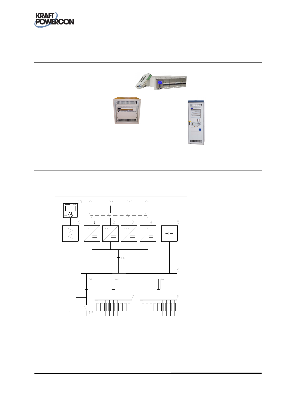
4.2 APPLICATION EXAMPLE
PRM1/PRM1-W is intended for integration in a complete DC system. An example of such is shown
in the simplified schematic below.
Figure 1 Application example PRM1
1-4: Rectifier modules (T1-4), PRM1 9: I/O unit (K1), PRM1
5: Battery 10: Operator panel (P1), PRM1
6: Battery block 11: Alarm outputs
7-8: Distribution unit 12: Capacity test terminals
KraftPowercon Sweden AB, Hjalmar Petris väg 49, S-352 46 Växjö, Sweden, Tel: +46 470-705200, Fax: +46 470-705201,
www.kraftpowercon.com
 Loading...