

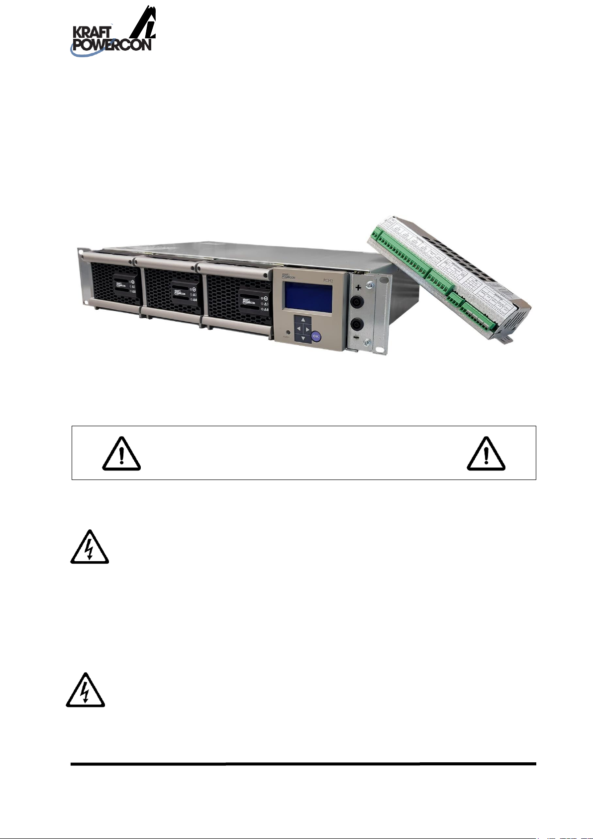
Manual for
charging rectifier
type PRM1
SAFETY INSTRUCTIONS
Manual: 9-1718-A
P/n: 0001138
You must read this manual before installation, use or work on the product.
This product contains dangerous voltages that when touched can cause electric shock, burns
or death.
The product must be installed by qualified personnel and according to the installation
instructions. Service may only be performed by authorized service personnel. The equipment
housing may only be removed by authorised personnel when all power has been cut to the
equipment for at least five minutes. The protective covers and contact safety devices inside the
equipment may only be removed by authorised service personnel.
The power must always be disconnected in a safe way before starting any service/maintenance.
Warning for reverse voltage. Power is supplied from several sources.
KraftPowercon Sweden AB, Hjalmar Petris väg 49, 352 46 Växjö, Sweden, Tel: 0470-705200, Fax: 0470-705201,
www.kraftpowercon.com

2
We reserve the right to make changes to the content of this manual without prior notification.
KraftPowercon Sweden AB, Hjalmar Petris väg 49, 352 46 Växjö, Sweden, Tel: 0470-705200, Fax: 0470-705201,
www.kraftpowercon.com

3
CONTENTS
1 PRESENTATION .............................................................................................. 5
2 SAFETY INSTRUCTIONS ............................................................................... 6
3 TECHNICAL DATA ........................................................................................ 7
3.1 ELEKTRICAL DATA .............................................................................................................................. 7
3.1.1 Assortment .......................................................................................................................................... 7
3.1.2 Common electrical input data .......................................................................................................... 7
3.1.3 Common electrical output data ........................................................................................................ 7
3.1.4 Electrical data for rectifier module ................................................................................................... 8
3.2 ENVIRONMENTAL DATA .................................................................................................................. 8
3.3 MECHANICAL DATA .......................................................................................................................... 8
3.4 CONFORMITY WITH STANDARDS .................................................................................................. 9
4 FUNCTIONAL DESCRIPTION .................................................................... 10
4.1 GENERAL .............................................................................................................................................. 10
4.2 APPLICATION EXAMPLE ................................................................................................................. 10
4.3 LIKRIKTARMODULER ....................................................................................................................... 11
4.4 RACK FOR RECTIFIER MODULES AND OPERATOR PANEL ................................................... 11
4.5 TEST CONTACTS ................................................................................................................................. 11
4.6 I/O UNIT ................................................................................................................................................ 11
4.7 FUNCTIONS .......................................................................................................................................... 11
4.7.1 General ............................................................................................................................................... 11
4.7.2 Float charging ................................................................................................................................... 12
4.7.3 Equalization charging ...................................................................................................................... 12
4.7.4 Battery circuit test ............................................................................................................................. 12
5 OPERATION ................................................................................................... 13
5.1 GENERAL .............................................................................................................................................. 13
5.2 OPERATOR PANEL ............................................................................................................................. 13
5.3 RECTIFIER MODULES ........................................................................................................................ 13
5.4 MAINS SUPPLY .................................................................................................................................... 13
5.5 TEST CONTACTS ................................................................................................................................. 14
6 INSTALLATION INSTRUCTIONS ............................................................. 15
6.1 SAFETY INSTRUCTIONS ................................................................................................................... 15
6.2 GENERAL .............................................................................................................................................. 15
6.3 STORAGE AND PROTECTION ......................................................................................................... 15
6.4 MOUNTING .......................................................................................................................................... 15
6.4.1 General ............................................................................................................................................... 15
6.4.2 Rack .................................................................................................................................................... 15
6.4.2.1 I/O Unit ......................................................................................................................................... 15
6.5 ELECTRICAL INSTALLATION ......................................................................................................... 15
6.5.1 General ............................................................................................................................................... 15
6.5.2 Earthing ............................................................................................................................................. 16
6.5.3 Mains voltage .................................................................................................................................... 16
6.5.3.1 External fuse rating ..................................................................................................................... 16
6.5.3.2 Connection .................................................................................................................................... 16
6.5.4 Battery/Load ...................................................................................................................................... 16
KraftPowercon Sweden AB, Hjalmar Petris väg 49, 352 46 Växjö, Sweden, Tel: 0470-705200, Fax: 0470-705201,
www.kraftpowercon.com

4
6.5.5 Rectifier modules .............................................................................................................................. 17
6.5.6 I/O Unit .............................................................................................................................................. 17
6.5.6.1 General .......................................................................................................................................... 17
6.5.6.2 Communication cable ................................................................................................................. 17
6.5.6.3 Power supply ............................................................................................................................... 17
6.5.7 Operator panel .................................................................................................................................. 18
6.5.8 Test contacts ...................................................................................................................................... 18
7 STARTING UP ................................................................................................ 19
7.1 SAFETY INSTRUCTIONS ................................................................................................................... 19
7.2 PREPARATORY INSPECTION .......................................................................................................... 19
7.2.1 General ............................................................................................................................................... 19
7.3 POWERING UP ..................................................................................................................................... 19
7.3.1 DC ....................................................................................................................................................... 19
7.3.2 AC ....................................................................................................................................................... 19
7.4 CHECKING THE CHARGING VOLTAGE ...................................................................................... 19
7.5 CHECKING THE SETTINGS .............................................................................................................. 20
7.6 CHECKING THE OUTPUTS ............................................................................................................... 20
8 MAINTENANCE ............................................................................................ 21
8.1 ANNUAL INSPECTION...................................................................................................................... 21
8.1.1 General ............................................................................................................................................... 21
8.1.2 Checking the charging voltage ....................................................................................................... 21
8.1.3 Checking the cooling capacity ........................................................................................................ 21
9 FAULT TRACING .......................................................................................... 22
9.1 SAFETY INSTRUCTIONS ................................................................................................................... 22
9.2 FAULT TRACING FOLLOWING ALARM ....................................................................................... 22
9.3 OTHER FAULT TRACING.................................................................................................................. 22
Bilagor
A LAYOUT AND DIMENSION, PRM1
B CIRCUIT DIAGRAM, PRM1
KraftPowercon Sweden AB, Hjalmar Petris väg 49, 352 46 Växjö, Sweden, Tel: 0470-705200, Fax: 0470-705201,
www.kraftpowercon.com

1 PRESENTATION
PRM1 is a complete charge rectifier with built-in monitoring, intended for mounting in a 19”
rack.
The system is built on a modular basis for easy service and high flexibility. Its compact design
allows it to be used even in confined spaces. The clear display and well-arranged system of
menus of the monitoring unit make it easy and pleasant to work with. The rectifiers are of
“plug-in” type and can be connected in parallel to increase capacity and availability.
This description primarily deals with all installation, commissioning, service, maintenance
and technical data and is principally aimed at the personnel who are responsible for these
areas. An equivalent description of the parts of the equipment that relate to the monitoring
unit are detailed in the Manual for monitoring unit type PCM2.
Operation is handled primarily via the monitoring unit described in the Manual for monitoring
unit type PCM2. This is therefore chiefly aimed at the personnel that have the day to day
responsibility for the plant, but also to other personnel who have cause to work with the D.C.
system.
For a complete description, this manual is to be used together with the description for the
monitoring unit, Manual for monitoring unit type PCM2.
5
KraftPowercon Sweden AB, Hjalmar Petris väg 49, 352 46 Växjö, Sweden, Tel: 0470-705200, Fax: 0470-705201,
www.kraftpowercon.com

6
2 SAFETY INSTRUCTIONS
This product contains dangerous voltages that when touched can cause electric shock, burns
or death.
For safety reasons the concerned personnel are classified according to the following
requirements for specific skills.
Authorised service personnel:
• Have electrical training and adequate experience to avoid the dangers that electricity can
cause.
• Are certified to meet authority requirements for the work in question.
• Have linguistic skills that ensure that the content of this description cannot be
misunderstood.
• Have undergone a product-specific training programme for authorised service personnel
that are approved by KraftPowercon Sweden AB.
Qualified personnel:
• Have electrical training and adequate experience to avoid the dangers that electricity can
cause.
• Are certified to meet authority requirements for the work in question.
• Have linguistic skills that ensure that the content of this description cannot be
misunderstood.
Installation, service, maintenance and fault tracing may only be carried out by authorised
personnel and in accordance with the installation instructions.
The protective covers and contact safety devices inside the equipment may only be removed by
authorised service personnel.
KraftPowercon Sweden AB, Hjalmar Petris väg 49, 352 46 Växjö, Sweden, Tel: 0470-705200, Fax: 0470-705201,
www.kraftpowercon.com
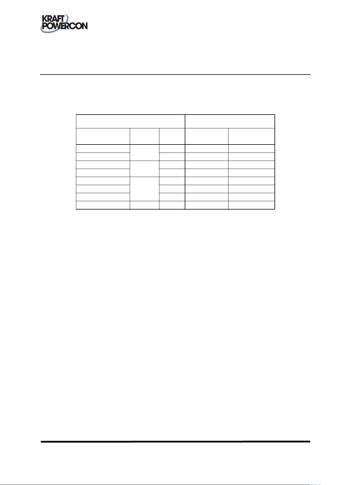
PRM1
Rectifier module
Model
designation
UNOM
IRATED
IRATED
Model
designation
(VDC)
(A)
(A)
PRM1 24/108
24
108
36
PCS 24/36
PRM1 24/210
210
70
PCS 24/70
PRM1 48/54
48
54
18
PCS 48/18
PRM1 48/150
150
50
PCS 48/50
PRM1 110/24
110
24
8
PCS 110/8
PRM1 110/48
48
16
PCS 110/16
PRM1 110/66
66
22
PCS 110/22
PRM1 220/30
220
30
10
PCS 220/10
3 TECHNICAL DATA
3.1 ELEKTRICAL DATA
3.1.1 Assortment
PRM1 can be equipped with up to three rectifier modules, depending on the model.
7
3.1.2 Common electrical input data
Rated voltage ............................................... 120*1/127*1/220/230/240 VAC 1- phase*2
Frequency ..................................................... 50/60 Hz
Power factor ................................................. > 0.99 at 230 VAC, full load
Connection ................................................... 6 mm2 screw terminal block per module
Other ............................................................. Mains switch and 2.5 m cable terminal rack included
*1
: Power derating below 190 VAC.
*2
: A single rectifier module is supplied from one phase, but several modules can each be
supplied from separate phases.
3.1.3 Common electrical output data
Voltage regulation (static) .......................... <±0.5 % of nominal output voltage
Voltage regulation (dynamic) .................... <±1 % within 3 seconds, 0-100 / 100-10 % load change
Current regulation....................................... <±1 % of rated current
Setting range, current limit ........................ 0 – 100 % of rated current
Ripple voltage .............................................. <0.1 %RMS
Ripple current .............................................. <0.1 % of rated current
Efficiency, typical ........................................ up to 92 %
Connection ................................................... For rated voltage:
24 V: 10 or 16 mm2 cable, 3 m included
48 V: 10 mm2 cable, 3 m included
110 V: 6 mm2 cable, 3 m included
220 V: 6 mm2 cable, 3 m included
*1
*1
: Depending on rectifier module
KraftPowercon Sweden AB, Hjalmar Petris väg 49, 352 46 Växjö, Sweden, Tel: 0470-705200, Fax: 0470-705201,
www.kraftpowercon.com

Model
designation,
rectifier
module
Output data
Input data
Power
loss*2
(W)
UNOM
Setting
range
IRATED
PMAX
Voltage
range
*3
Mains
power*1
Mains
current*1
(VDC)
(VDC)
(A)
(W)
(VAC)
(VA)
(Arms)
PCS 24/36
24
22 – 33
36
1000
90 - 290
1150
6
150
PCS 24/70
70
2000
90 - 290
2200
12
175
PCS 48/18
48
42 - 63
18
1000
90 - 290
1150
6
135
PCS 48/50
50
2700
90 - 290
2900
15
210
PCS 110/8
110
100 - 158
8
1000
90 - 290
1150
6
135
PCS 110/16
16
2000
90 - 290
2200
12
160
PCS 110/22
22
2700
90 - 290
2900
15
200
PCS 220/10
220
187 – 292
10
2475
90 - 290
2700
14
200
3.1.4 Electrical data for rectifier module
*1
: max at 195 VAC
*2
: typical at 230 VAC and full load
*3
: Power derating below 190 VAC.
8
3.2 ENVIRONMENTAL DATA
Class of enclosure ...................................................... IP20 as per EN 60529
Cooling........................................................................ Temperature controlled fans in rectifier
Ambient temperature (spec. data applies) ............. 0 to +40 °C
Storage temperature .................................................. -40 to +70 °C
Humidity .................................................................... <90 % RH, non-condensed
Altitude a.s.l ............................................................... <2000 m
Noise level, at 1m ...................................................... <50 dBA at 25 % last
3.3 MECHANICAL DATA
Version .....................................Rack for 19” frame
Placement ................................Indoors in dry, clean room
Mounting, rack .......................Mounted in 19” rack
Mounting, I/O-module ..........Mounted on 35 mm guide
Weight ......................................14 kg, fully equipped with 3 rectifier modules
Dimensions, rack ....................2 HU, 88.2/481.5/315 mm (h/w/d), see also dimension diagram
Dimensions, I/O-module .......117/224/66 mm (h/w/d), see also dimension diagram Appendix_A
Colour, rack .............................Colorless galvanized sheet
modules
rails or directly on
mounting plate
Appendix_A
KraftPowercon Sweden AB, Hjalmar Petris väg 49, 352 46 Växjö, Sweden, Tel: 0470-705200, Fax: 0470-705201,
www.kraftpowercon.com

3.4 CONFORMITY WITH STANDARDS
EN 60529 .............................. Encapsulation class IP20
EN 50178 .............................. LVD. Electronic equipment, including power electronics in electrical
power installations.
EN 61000-6-2 ....................... EMC. Immunity for industrial electronics
EN 61000-6-4 ....................... EMC. Emission from equipment in an industrial environment
9
KraftPowercon Sweden AB, Hjalmar Petris väg 49, 352 46 Växjö, Sweden, Tel: 0470-705200, Fax: 0470-705201,
www.kraftpowercon.com

4 FUNCTIONAL DESCRIPTION
4.1 GENERAL
PRM1 is a complete rectifier unit with
built-in monitoring, intended for
mounting in a 19” rack.
Most functions are handled by the monitoring unit and are described in the Manual for
monitoring unit PCM2. Only the functions that feature at a general rectifier level are described
here.
4.2 APPLICATION EXAMPLE
PRM1 is intended for integration in a complete DC system. An example of such is shown in the
simplified schematic below.
10
Figur 1 Applikationsexempel PRM1
1-3: Rectifier modules (T1-3), PRM1 9: I/O unit (K1), PRM1
5: Battery 10: Operator panel (P1), PRM1
6: Battery block 11: Alarm outputs
7-8: Distribution unit 12: Capacity test terminals
KraftPowercon Sweden AB, Hjalmar Petris väg 49, 352 46 Växjö, Sweden, Tel: 0470-705200, Fax: 0470-705201,
www.kraftpowercon.com

4.3 LIKRIKTARMODULER
The rectifier modules are of the “plug-in” type and can in principle be replaced during
operation. Depending on the model, up to three parallel modules can be fitted.
There are three indicator lamps on the front of the module:
AC OK - Green: Mains OK
Off: Mains power failure
WARNING -Yellow (permanent): Remote shutdown (standby) or
high temperature warning
Yellow (flashing): Communication fault
Off: Normal operation
ALARM - Off: OK
Red: Alarm (shutdown after DC overvoltage,
over temperature, fan error or internal fault)
11
4.4 RACK FOR RECTIFIER MODULES AND OPERATOR PANEL
The rack unit contains the operator panel and the rectifier modules.
The operator panel P1 is the unit used as the user interface. It is mounted modularly to the right
of the rectifier modules.
The rectifier modules (T1 – T3) are ”plug-in” modules.
4.5 TEST CONTACTS
There are short-circuit proof test contacts (X30) alongside the operator panel, for checking the
battery voltage. The test contacts accept 4 mm banana plugs.
4.6 I/O UNIT
The I/O unit contains connection terminals for the external connections required for the
monitoring unit.
4.7 FUNCTIONS
4.7.1 General
Only the most important functions are specified here. For more information, see the Manual for
monitoring unit PCM2.
KraftPowercon Sweden AB, Hjalmar Petris väg 49, 352 46 Växjö, Sweden, Tel: 0470-705200, Fax: 0470-705201,
www.kraftpowercon.com

4.7.2 Float charging
Float charging is the normal operating mode determined by the battery. The voltage level is to
be set according to the battery manufacturer’s instructions.
For more information, see the Manual for monitoring unit PCM2.
4.7.3 Equalization charging
Equalization charging means charging at an increased voltage level over a limited period. It is
used partly for the initial charge, and partly for equalizing cell voltages if spreading has
occurred.
For more information, see the Manual for monitoring unit PCM2.
WARNING! Generally, batteries of VR-type (vent regulated) should not be subject to equalization
charging. For some battery types equalization charging could even be harmful to the batteries. Always
follow the battery manufacturer’s instructions.
12
4.7.4 Battery circuit test
A battery circuit test is automatically carried out at optional intervals (normally once a day).
The test involves checking that the entire battery circuit, i.e. not only the battery block, is in
working order.
For more information, see the Manual for monitoring unit PCM2.
KraftPowercon Sweden AB, Hjalmar Petris väg 49, 352 46 Växjö, Sweden, Tel: 0470-705200, Fax: 0470-705201,
www.kraftpowercon.com

5 OPERATION
5.1 GENERAL
Most of the operation is associated with the monitoring unit. This is described in the Manual for
monitoring unit PCM2. Other operation is detailed in this section.
5.2 OPERATOR PANEL
The operator panel is the link between the equipment and the user. It is made up
of a display, a keypad and an LED. Operation is described in the Manual for
monitoring unit PCM2.
13
5.3 RECTIFIER MODULES
There are three indicator LEDs on the front of the rectifier
module with the following functions:
AC OK - Green: Mains OK
Off: Mains power failure
WARNING -Yellow (permanent): Remote shutdown (standby) or
high temperature warning
Yellow (flashing): Communication fault
Off: Normal operation
ALARM - Off: OK
Red: Alarm (shutdown after DC overvoltage,
over temperature, fan error or internal fault)
When the module gives an alarm you have the option of finding out the cause of the alarm in
detail via the operator panel menus, see the Manual for monitoring unit PCM2.
The modules are of the ”plug-in” type and can in principle be replaced during operation. For
more information, see the INSTALLATION INSTRUCTIONS section.
5.4 MAINS SUPPLY
PRM1 is supplied with a cable stump (phase, neutral, earth) per rectifier module. The rectifier
modules can therefore be supplied either from one common phase or from separate phases.
KraftPowercon Sweden AB, Hjalmar Petris väg 49, 352 46 Växjö, Sweden, Tel: 0470-705200, Fax: 0470-705201,
www.kraftpowercon.com

5.5 TEST CONTACTS
When measuring the battery voltage you should avoid measuring
directly on the battery poles, due to the risk of arcing in the event of a
possible short circuit. Instead, use the short-circuit protected test
contacts just below the operator panel.
The test contacts accept 4 mm insulated safety plugs, and also 4 mm
banana plugs. To avoid measurement errors, the voltmeter used
should have high internal resistance, 10 Mohm or better.
14
KraftPowercon Sweden AB, Hjalmar Petris väg 49, 352 46 Växjö, Sweden, Tel: 0470-705200, Fax: 0470-705201,
www.kraftpowercon.com

6 INSTALLATION INSTRUCTIONS
6.1 SAFETY INSTRUCTIONS
WARNING! This product contains dangerous voltages that when touched can cause electric shock,
burns or death. Protective earth must always be connected in a reliable way to avoid the risk of live parts
in the equipment in the event of faults. No live parts are permitted during installation. The product must
be installed by qualified personnel (see SAFETY INSTRUCTIONS section 2.)
WARNING! Check both before and after setting-up that the equipment does not have any mechanical
damage. Check that the equipment is designed for the existing rated voltage. Cables for input and output
power must be correctly dimensioned to avoid fire hazard.
6.2 GENERAL
15
Installation of parts belonging to the monitoring unit is not dealt with in this manual. For
complete installation instructions these instructions should therefore be used in combination
with the installation instructions included in the Manual for monitoring unit PCM2.
6.3 STORAGE AND PROTECTION
Storage is to be in a dry area and at a temperature within the -40 to +70 °C range.
6.4 MOUNTING
6.4.1 General
The equipment is intended for placement in a dry, clean environment that is free from
conductive dust. For EMC reasons, both rack and I/O unit must be placed within the same
metal enclosure and the supplied ferrite cores and mains filters are used as intended.
6.4.2 Rack
Mount the rack unit in a 19” rack frame. Make sure there is sufficient space for ventilation, see
Appendix A, DIMENSION DIAGRAM.
6.4.2.1 I/O Unit
The I/O unit is supplied with adapters for 35 mm guide rails. The unit can also be mounted
directly on a flat surface by removing the adapters first. Make sure that the distance between
the rack and I/O unit is sufficiently close for the supplied 2 m cable to reach.
6.5 ELECTRICAL INSTALLATION
6.5.1 General
The equipment is designed for permanent installation. Protective earth must be connected
before any other installation.
KraftPowercon Sweden AB, Hjalmar Petris väg 49, 352 46 Växjö, Sweden, Tel: 0470-705200, Fax: 0470-705201,
www.kraftpowercon.com

6.5.2 Earthing
Earth the rack using the 6 mm2 earthing wire connected to the back plane in the rack.
Earth the I/O unit via the 1.5 mm2 earthing wire connected to the unit’s cover.
6.5.3 Mains voltage
6.5.3.1 External fuse rating
The size of the external primary fuse is selected as follows:
1. Find the maximum mains current for the type of rectifier module in question from the
table in section Electrical data for rectifier module.
2. Multiply it by the number of rectifier modules.
3. Choose the next highest fuse rating.
NOTE: If you choose to feed the rectifier modules from different phases (see below), point 2
above must naturally be suitably modified.
6.5.3.2 Connection
16
Each rectifier module has its own wiring for
phase and neutral. It is therefore possible to
select between feeding the modules from
individual phases or to connect two or more
modules in parallel to the same phase. To
simplify this, the terminal blocks are fitted with
bipolar connection links that can be moved or
removed. At delivery, all mains inputs are
connected in parallel.
Note that since the PRM1 holds a maximum of
three modules, the fourth terminal is not
connected to any module.
Between the terminals is a mains filter that must be connected in order for the EMC properties
to apply.
The feeding network should be of TN-S type in order to avoid the risk of stray current.
6.5.4 Battery/Load
Check that the rectifier's rating plate shows a rated voltage that conforms with the battery's
nominal voltage.
WARNING! The rectifiers DC output has no internally fuse. Ensure that an external fuse is within the
circuit when connection against battery is performed.
Please note: Make sure to check the polarity before installation and commissioning.
Wrong polarity may cause damage to the rectifier module(s).
From DC rails on the back of the rack, the DC output cables, red for plus and blue for minus,
should be connected to a common mounting element in the battery central. For some models
with a slightly higher current, there are several cables for each pole that must then be connected
in parallel. For EMC reasons, the cables, depending on the model, are wrapped one or two turns
KraftPowercon Sweden AB, Hjalmar Petris väg 49, 352 46 Växjö, Sweden, Tel: 0470-705200, Fax: 0470-705201,
www.kraftpowercon.com

around a ferrite core. If they have to be replaced or extended, be sure to select cables that are
dimensioned to withstand the rectifier's rated current.
6.5.5 Rectifier modules
The rectifier modules are normally packed separately and are to be put in
place during the installation. The rack module slots should be equipped
with modules starting from the leftmost position and with spare slots to
the right.
The modules can in principle be replaced during operation. However, we
recommend disconnection of the mains supply first.
Loosen the two screws on the upper handle of the handle. It loosens a
handle that is angled downwards so that it can then pull out the module
from its place.
Conversely, a module is installed by gently pushing the module into
place and pushing it into the bottom. Then push the handle towards the
module and finally secure the handle with the two screws.
WARNING! Check carefully that the rectifier modules have the correct rated voltage.
17
6.5.6 I/O Unit
6.5.6.1 General
All the connections to the monitoring units are grouped in a unit called
the I/O unit. The connectors are pluggable, i.e. they can be removed for
better accessibility when installing. Only the connections that are made
between the rack unit and I/O unit via the supplied PRM1 wiring are
described here.
For other connections to the I/O unit, see Manual for monitoring unit
PCM2.
6.5.6.2 Communication cable
The supplied RJ45 cable (standard network cable) is already connected to the operator panel in
the rack at one end, the other end shall be connected to the I/O-unit connector X4. Note that
there are two physically identical connectors beside each other; X3 and X4. X4 is closest to the
short side of the unit.
6.5.6.3 Power supply
The power supply cable for the monitoring unit is supplied and is connected at one end to the
I/O-units screw terminal block X5 and is provided with a ferrite core for EMC reasons.
The second end is suitably connected to a fuse group in the battery central, cord no. 422 (from
X5:1) to minus and cable 423 (from X5:2) to plus.
KraftPowercon Sweden AB, Hjalmar Petris väg 49, 352 46 Växjö, Sweden, Tel: 0470-705200, Fax: 0470-705201,
www.kraftpowercon.com

6.5.7 Operator panel
The operator’s panel is already installed at delivery. The following
description is mainly intended for service in the future.
To loosen the operator panel, first loosen the two screws that hold
the carrier plate (see upper picture). On the back of the panel are two
cables that can now be disconnected. Then loosen the screws on the
back of the carrier plate holding the operator panel itself.
To mount the panel, the operator panel is fastened with screws from
the back of the carrier plate. Then connect the two cables. Finally,
attach the carrier plate to the rack with the two screws on the front.
6.5.8 Test contacts
The I/O unit’s connection terminal X7 has a contact for a short-circuit proof test contact, used to
measure the battery voltage. Use the enclosed cable to connect X7: 1 and X7: 6 marked 424 and
429 to the measurement terminal located just below the operator panel.
Use the enclosed cord to connect X7: 1 and X7: 6 marked 424 respectively 429 to the test contacts
located just to the right of the operator panel.
18
KraftPowercon Sweden AB, Hjalmar Petris väg 49, 352 46 Växjö, Sweden, Tel: 0470-705200, Fax: 0470-705201,
www.kraftpowercon.com

7 STARTING UP
7.1 SAFETY INSTRUCTIONS
WARNING! This product contains dangerous voltages that when touched can cause electric shock,
burns or death. All contact safety devices and plates must be fitted when operating.
7.2 PREPARATORY INSPECTION
7.2.1 General
Check that the equipment is free from damage, correctly fitted and that all the ventilation
openings are free from obstacles.
Check that all cable installations, electrical connections and protective earths are correctly
implemented.
Check that all protective covers are intact.
Check that the number of battery blocks is according to specification.
19
7.3 POWERING UP
7.3.1 DC
First connect the rectifier to the battery by, for example, connecting a fuse in the battery circuit.
Note that there is a connection current when the output capacitors of the rectifier modules are
charged. This can give rise to some sparking at the connection point.
After a few seconds, the operator panel display lights up and after a few more seconds, text
appears on the display. All measured values are initially zeroed. After about 10 seconds, the
measurements begin. Only after a total of about 30 seconds have passed, any alarms are
activated.
7.3.2 AC
Turn on mains breaker. The rectifier modules should now start up.
The battery now starts to charge, and if it was in a state of deep
discharge, the charging starts with rated current until the float charging
level is reached. Certain types of batteries require an initial equalizing
charging. Always follow the recommendations given by the battery manufacturer.
7.4 CHECKING THE CHARGING VOLTAGE
Check the settings of the monitoring unit to ensure that the voltage level for float charging and
equalizing charging conform to the battery manufacturer's specifications, see Manual for
monitoring unit PCM2.
KraftPowercon Sweden AB, Hjalmar Petris väg 49, 352 46 Växjö, Sweden, Tel: 0470-705200, Fax: 0470-705201,
www.kraftpowercon.com

When the battery is charged to a level where the ”High current” alarm is no longer active, you
should check that the actual output voltage conforms with the setting of the float charging
voltage, see section 8.1.1 Checking the charging voltage.
7.5 CHECKING THE SETTINGS
Each time the monitoring unit has been powered down, the built-in clock must be reset with the
current date and time, see the Manual for monitoring unit PCM2.
Check that the measurements on the display agree with the actual situation. Check that the
parameters for charging voltages, alarms and other parameters conform to the intended
functions, see the Manual for monitoring unit PCM2.
7.6 CHECKING THE OUTPUTS
The alarm outputs A-D and the output for fan control can be operated manually for simple and
smooth checking of external circuits, see the Manual for monitoring unit PCM2.
20
KraftPowercon Sweden AB, Hjalmar Petris väg 49, 352 46 Växjö, Sweden, Tel: 0470-705200, Fax: 0470-705201,
www.kraftpowercon.com

8 MAINTENANCE
8.1 ANNUAL INSPECTION
8.1.1 General
In addition to these instructions, you must observe the instructions for maintenance in the
Manual for monitoring unit PCM2 and the battery manufacturer's maintenance instructions.
8.1.2 Checking the charging voltage
Connect a voltmeter to the test contacts (see section Fel! Hittar inte referenskälla.).
Check that the rectifier's output voltage corresponds to the setting of the float charging level.
If the float charging voltage is temperature controlled, it is difficult to determine what the
expected output voltage should be. The solution is to temporarily shut down the temperature
control. You do this using the menu option Functions, battery temperature to specify that the
temperature sensor is not installed (see the Manual for monitoring unit PCM2, section Operation,
Functions). Do not forget If charge voltage is found to be in a state of non-conformance it is
therefore the voltage measurement that should be calibrated, see the instructions for
maintenance in the Manual for monitoring unit PCM2.to reset the parameter for the installed
temperature sensor following the completed measurement!
All control is based on measurement.
21
8.1.3 Checking the cooling capacity
Check that the rectifier modules’ ventilation vents are not clogged with dust or other
contaminants. Clean where necessary.
KraftPowercon Sweden AB, Hjalmar Petris väg 49, 352 46 Växjö, Sweden, Tel: 0470-705200, Fax: 0470-705201,
www.kraftpowercon.com

9 FAULT TRACING
9.1 SAFETY INSTRUCTIONS
WARNING! This product contains dangerous voltage that when touched can cause electric shock, burns
or death.
Service/maintenance work that involves working with removed contact protection devices may only be
carried out by authorised service personnel (see section 2 SAFETY INSTRUCTIONS).
WARNING! In the event of overvoltage, the electrolytic capacitors and varistors may explode. If work
must be done when the equipment is powered up and with exposed circuit boards, splinter protection
must therefore be used (protective goggles and screens).
9.2 FAULT TRACING FOLLOWING ALARM
22
Fault tracing in connection with alarm messages is described in the Manual for monitoring unit
PCM2.
9.3 OTHER FAULT TRACING
The type of faults that can be attributed to the rectifier in general are dealt with here. For faults
that relate to the monitoring unit see the Manual for monitoring unit PCM2.
The primary fuse trips when the rectifier is turned on
Cause 1: Incorrect type of mains fuse. Check that the mains fuse observes the specifications in
section 6.5.3 External fuse rating.
Cause 2: Internal rectifier module fault. Install one module at a time in order to identify the
module that is responsible for the problem. Replace the defective module.
The rectifier has no output, green indicator lamp “AC OK” is out
Cause 1: Mains voltage missing. Check that there is mains voltage to the mains input
terminals and that the mains breaker is closed.
Cause 2: Rectifier modules are not properly inserted.
The rectifier has no output, green indicator lamp ”AC OK” is lit, yellow indicator lamp
”WARNING” is lit and red indicator lamp ”ALARM” is off
Cause 1: Input ”EXT. FAULT” is used as external blocking and is in open state.
Cause 2: The rectifier module has been switched off due to overtemperature. Check that the
rectifier modules´ ventilation vents are not clogged with dust or other contaminants.
Clean where necessary. Check that the ambient temperature is within permitted
limits.
The rectifier has no output, green indicator lamp ”AC OK” is lit, yellow indicator lamp
”WARNING” and red indicator lamp ”ALARM” are off
Cause 1: Output fuses has tripped. Check that the output fuses are properly dimensioned to
handle the rectifier's rated current.
KraftPowercon Sweden AB, Hjalmar Petris väg 49, 352 46 Växjö, Sweden, Tel: 0470-705200, Fax: 0470-705201,
www.kraftpowercon.com

23
The rectifier module’s green indicator lamp ”AC OK” and red indicator lamp ”ALARM” are
lit
Cause 1: The rectifier module has been switched off due to overtemperature. Check that the
rectifier modules´ ventilation vents are not clogged with dust or other contaminants.
Clean where necessary. Check that the ambient temperature is within permitted
limits.
Cause 2: The rectifier module has been switched off due to fan error in the module. Replace
the fan or the entire rectifier module.
Cause 3: The rectifier module has been tripped by high output voltage, HVSD (High Voltage
Shut Down).Reset by removing power to the module, most simply by extracting the
module for a few seconds until all lamps are off, and then re-inserting it again. If the
fault reoccurs, the module may be faulty. Replace the rectifier module.
Cause 4: Other internal fault in the rectifier module. Replace the rectifier module.
The rectifier module's red indicator lamp “ALM” is lit
Cause 1: Unless the cause is obvious, e.g. see the alternatives above, you can show the status
of the rectifier module in detail via the display on the monitoring unit, see the
Manual for monitoring unit PCM2.
The rectifier output voltage is too low
Cause 1: The rectifier load is above its capacity (rated current). This is normal in connection
with recharging following deep discharge.
Cause 2: Battery circuit test in progress. This is a test that is normally executed automatically
once a day.
Cause 3: The requested charging voltage is close to or above the level of the parameter
Umaximum. The voltage will be limited 1% below this level. If higher voltage is desired,
the setting of the parameter Umaximum must be increased., see the Manual for monitoring
unit PCM2.
Cause 4: High temperature in the battery/battery compartment. Only applicable if the rectifier
controls the temperature of the float charging voltage. There is no fault with the
rectifier in this case. Look for the fault in the high temperature instead. Alternatively
the temperature sensor could be defective. Check whether the display is reporting
the correct battery temperature.
Cause 5: Incorrectly set float charging voltage level. Adjust the setting.
Cause 6: Incorrectly calibrated voltage measurement. Recalibrate the monitoring unit's
measurement of battery voltage.
The rectifier output voltage is too high
Cause 1: Equalizing charging in progress. This has either been initiated manually or
automatically following a power failure.
Cause 2: Low temperature in the battery/battery compartment. Only applicable if the rectifier
controls the temperature of the float charging voltage. There is no fault with the
rectifier in this case. Look for the fault in the low temperature instead. Alternatively
the temperature sensor could be defective. Check whether the display is reporting
the correct battery temperature.
Cause 3: Incorrectly set float charging voltage level. Adjust the setting.
Cause 4: Incorrectly calibrated voltage measurement. Recalibrate the monitoring unit's
measurement of battery voltage.
KraftPowercon Sweden AB, Hjalmar Petris väg 49, 352 46 Växjö, Sweden, Tel: 0470-705200, Fax: 0470-705201,
www.kraftpowercon.com

Date
Sign
Revision
Rev.
Drawing No.
This page
Date
Approved
Drawn
Design
Rev
F
E
D
C
B
A
1
2
3
4
5
6
7
8
Next page
Document type
ALARM
PCM2
OK
-Q1
-X11
[L]
-X11
[N]
-R1
Charging rectifier system type PRM1
for rectifier modules type PCS
2018-02-20
12062
A
MP
MP
1
-
Layout drawing
PRM1
KeBe
224
117
46
66*
* When mounted on
NS 35/7,5 bar
I/O unit, front view
I/O unit, side view
76.2
88.2
465
481.5
Rectifier subrack, front view
Rectifier subrack, side view
315
Air flow
Front
80
Minimum free
space for air flow
Mains breaker and terminals
Appendix A
LAYOUT AND DIMENSION, PRM1
KraftPowercon Sweden AB, Hjalmar Petris väg 49, 352 46 Växjö, Sweden, Tel: 0470-705200, Fax: 0470-705201,
www.kraftpowercon.com

Appendix B
CIRCUIT DIAGRAM, PRM1
KraftPowercon Sweden AB, Hjalmar Petris väg 49, 352 46 Växjö, Sweden, Tel: 0470-705200, Fax: 0470-705201,
www.kraftpowercon.com

KraftPowercon Sweden AB, Hjalmar Petris väg 49, 352 46 Växjö, Sweden, Tel: 0470-705200, Fax: 0470-705201,
www.kraftpowercon.com
 Loading...