

Kraft Power KCM-CKCM-CCKCM, KRBP-CKRB-CCKRB, KCG-CKCG-CCKCG, KDM-CKDM-CCKDM, KDMB-CKDMB-CCKDMB Operation And Maintenance Manual
...
N
n
T
L
A
C
0
–
M
J
d
S
S
2
FI
AL OPERA
ION AND M
ORDEN D
FM
INTENANC
E COMPRA
TECHNOL
E MANUAL
H336073-P
OGIES PRO
MINA MINI
031/A 45011
ECT B6042
TRO HALE
90525
PROJECT
FMCTech
ologiesChile
tda.Callao#2
970Oficina7
4EdificioStu
ioLasCondes
Fono:56‐2‐2
320825


INDEX
1
CONTENTS PAGE
DESCRIPTION 2
OPERATION 2 to 4
ADVANTAGES 4
CHARACTERISTIC CURVES 5
VERSIONS 6
LAYOUTS 6
SELECTION 7 to 10
DIMENSIONS 11 to 23
OIL FILL 24
SAFETY DEVICES 24 to 27
STANDARD AND REVERSE MOUNTING 28
APPLICATIONS 29
OTHER TRANSFLUID PRODUCTS 30
DESCRIPTION & OPERATING CONDITIONS
2
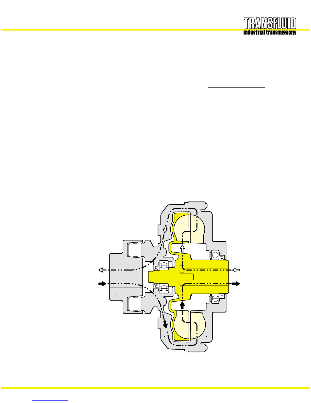
DESCRIPTION
The TRANSFLUID coupling (K series) is a constant filling type
comprising three main elements:
1 Driving impeller (pump) mounted on the input shaft.
2 Driven impeller (turbine) mounted on the output shaft.
3 Cover, flanged to the output impeller, with an oil-tight seal.
The first two elements can work both as pump and/or turbine.
OPERATING CONDITIONS
The TRANSFLUID coupling is a hydrokinetic transmission. The
impellers perform like a centrifugal pump and a hydraulic turbine.
With an input drive to the pump (i.e. electric motor or Diesel
engine) kinetic energy is imparted to the oil in the coupling. The oil
moves by centrifugal force across the blades of the turbine towards
the outside of the coupling.
This absorbs the kinetic energy and develops a torque which is
always equal to input torque thus causing rotation of the output
shaft. The wear is practically zero since there are no mechanical
connections.
The efficiency is influenced only by the speed difference (slip)
between pump and turbine.
The slip is essential to the functioning of the coupling: there could
not be torque transmission without slip! The for mula for slip, from
which the power loss can be deduced is as follows:
slip % = x 100
In normal conditions (standard duty), slip can vary from 1.5%
(large power) to 6% (small power).
TRANSFLUID couplings follow the laws of all centrifugal machines:
1 Transmitted torque is proportional to the square of input speed;
2 Transmitted power is proportional to the cube of input speed;
3 Transmitted power is proportional to the fifth power of circuit
outside diameter.
input speed – output speed
input speed
1 INTERNAL IMPELLER
2 EXTERNAL IMPELLER
3 COVER
4 FLEX COUPLING
1
2
3
4
OUTPUT
INPUT
OUTPUT
INPUT

FLUID COUPLING FITTED ON ELECTRIC MOTORS
3
TRANSFLUID COUPLING FITTED ON ELECTRIC MOT ORS
Three phase synchronous squirrel cage motors are able to supply
maximum torque only near 100% synchronous speed. Direct
starting the system utilized the most current. Figure 1 illustrates the
relationship between torque and current. It can be seen that the
absorbed current is proportional to the torque only between 85%
and 100% of the synchronous speed. With a motor connected
directly to the load, there are the following disadvantages:
– The difference between available torque and the torque required
by the load is very low until the rotor has accelerated to between
80-85% of the synchronous speed
– The absorbed current is high (up to 6 times the nominal current)
throughout the starting phase causing overheating of the
windings, overloads in the electrical lines and, in cases of
frequent starts, major production costs.
– Oversized motors are required by the limitations indicated abo ve.
To limit the absorbed current of the motor during the acceleration
of the load, a Y-D (wye – delta) star ting system is frequently used
which reduces the absorbed current by about 1/3 during starting.
Unfortunately, dur ing operation of the motor under the delta
configuration, the available torque is also reduced by 1/3 and for
machines with high inertias to accelerate, oversizing of the motor is
still required. Finally, this system does not eliminate current peaks
originating from the insertion or the commutation of the device.
Any drive system using a Transfluid fluid coupling has the
advantage of the motor starting without load. Figure 2 compares
the current demands of an electric motor when the load is directly
attached verses the demand when a fluid coupling is mounted
between the motor and load. The colored area shows the energy
that is lost, as heat, during start-up when a fluid coupling is not
used. A Transfluid fluid coupling reduces the motor’s current draw
during start-up thus reducing peak current demands. This not only
reduces power costs but also reduces brown outs in the power grid
and extends the life of the motor. Also at star t-up, a fluid coupling
allows more torque to pass to the load for acceleration than in drive
systems without a fluid coupling.
Figure 3 shows two curves for a single fluid coupling and a
characteristic curve of an electric motor. It is obvious from the stall
curve of the fluid coupling (s=100%) and the available motor
torque, how much torque is available to accelerate the rotor of the
motor (colored area). In about 1 second, the rotor of the motor
accelerates passing from point A to point B.The acceleration of the
load, however, is made gradually by the fluid coupling, utilizing the
motor in optimal conditions, along the part of the curve between
point B, 100% and point C, 2-5%. Point C is the typical point of
operation during normal running.
Fig. 1
Fig. 2
Fig. 3
% motor speed
% start-up time
% motor current
% torque
% motor speed
without fluid coupling
with fluid coupling

FLUID COUPLING WITH DELAYED-FILL CHAMBER
ADVANTAGES
4
TRANSFLUID FLUID COUPLINGS WITH A DELAYED FILL
CHAMBER
With the standard circuit in a maximum oil fill condition, fluid
couplings may transmit over
200% of the nominal motor torque. It
is possible to decrease the starting torque
down to 160% of the
nominal torque, by decreasing oil fill.This, however, leads to higher
slip and working temperature in the fluid coupling, during the
steady running conditions.
The most convenient solution to provide lower starting torque while
maintaining low slip at steady running is to provide a delayed fill
chamber mounted on the main circuit. This chamber holds a
percentage of the oil which at start-up is gradually released into the
main circuit through
calibrated bleed orifices as the coupling
spins.For couplings sized
15CK and above these orifices are set in
externally mounted valves.
The external mounting provides easy adjustment of the orifice size
which controls starting time and the maximum transmitted torque.
When the coupling is at rest, the
delay fill chamber contains a
percentage of oil quantity in the main circuit (Fig.
4a).This reduces
the torque
the coupling transmits and allows the motor to quickly
reach its steady running speed,
as if it was started without load.
As the coupling accelerates, the oil flows from the
delay fill
chamber
to the main circuit (Fig. 4b) at a rate proportional to the
coupling’s rotational speed.
The oil continues to transfer from the delay fill chamber the to the
main circuit emptying the delay fill chamber. Once all the oil is in
the main circuit (Fig.
4c) the coupling is then transmitting 100% of
the motor torque and the
minimum slip value is reached.
With a
single delay fill chamber, the ratio between starting and
nominal torque may reach
150 %.This ratio can be reduced to 120 %
with a double delay fill chamber
. This lower start-up torque
results from a smaller amount of oil in the main circuit due to more
oil in the bigger delay fill chamber.
Fluid couplings with single or double delay fill chamber provide
very smooth start-ups with low start-up torque transmission, and
this makes them excellent for applications with high inertia loads
and for use on belt conv eyors.
The single size chamber is available from size 11CK and above.
The double size chamber is available from size 15CCK and above
SUMMARY OF THE ADVANTAGES GIVEN BY FLUID
COUPLINGS:
– Very smooth start-ups
– Reduction of absorbed current during the starting phase: the
motor starts with very low load
–
Protection of the motor and the driven machine from jams and
overloads
– Utilization of asynchronous squirrel cage motors instead of
special motors with soft start devices
–
Longer life and up time of the whole drive train, thanks to the
protection provided by the fluid coupling
–
Energy saving, due to current peak reduction
–
Limits starting torque to 120% with a double delayed fill
chamber
–
Same torque at input and output: the motor can supply the
maximum torque even when load is jammed
– Torsional
vibration absorption for internal combustion engines,
thanks to the presence of a fluid as a power transmission
element
– Possibility to achieve a high number of
start-ups, or reversal of
the rotational direction.
–
Load balancing with dual motor drive: fluid couplings
automatically adjust load speed to the individual motor’s speed
–
High efficiency and minimum maintenance
– Viton rotating seals and O-rings
–
High resistance to corrosion by using cast aluminum for the
major coupling parts and providing
anticorrosion treatment on
smaller
cast iron and steel parts
ACCELERATION
valve
calibrated plug
All oil in circuit
into main circuit
Oil drains from chamber
for initial start
Oil available
use after start
Oil in reserve for
Fig. 4 c
RUNNING
Fig. 4 bFig. 4 a
AT REST
Fig. 4 a
AT REST
Fig. 4 b
ACCELERATION
Fig. 4 c
RUNNING
STARTING TORQUE CHARACTERISTICS
5
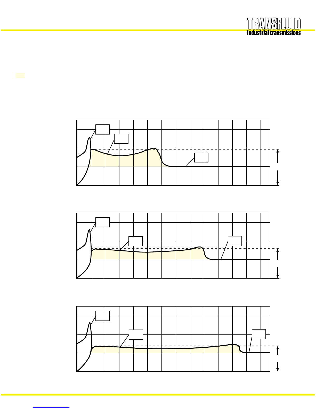
CHARACTERISTIC CURVES
MI : transmitted torque from fluid coupling
Mm : starting torque of the electric motor
Mn : nominal torque at full load
...... : accelerating torque
K type
(standard circuit)
CK type
(circuit with a
delayed chamber)
CCK type
(circuit with a double
delayed chamber)
Mm
MI
Mn
200%
100%
0510
Time [s]
180÷200%
Torque
Mm
Mn
200%
100%
0510
Time [s]
150÷180%
Torque
MI
Mm
200%
100%
0510
Time [s]
120÷150%
Torque
MI
Mn
PRODUCTION PROGRAM
Fig. F
Fig. G
21
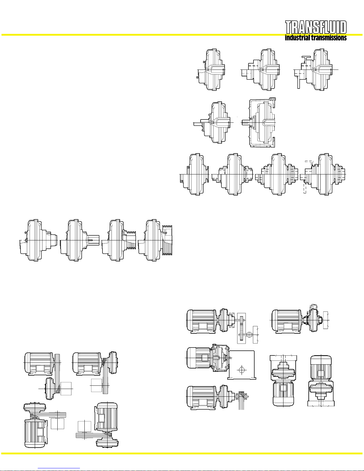
STANDARD MODELS
6
KRB
CKRBP - CCKRBPCKR - CCKR
KR
CKRG - CCKRG
KRG
KDMB
KDM
CKDMBP- CCKDMBPCKDM - CCKDM
KRD EK
KCG
KCM
CKRD - CCKRD
CKCG - CCKCGCKCM - CCKCM
Fig. B
Fig. D
21
Fig. A
Fig. C
Fig. E
PULLEY
KSD-QD–CKSD-QD
: fluid coupling that will use a QD style pulley
CCKSD-QD
KSD–CKSD–CCKSD
: basic coupling that accepts a flanged pulley,
with single (CK..) or double (CCK..) delayed fill
chamber
KSI-CKSI-CCKSI : fluid coupling with an incorporated pulley,
which is fitted from inside.
KSDF-CKSDF
: basic ..KSD coupling with flanged pulley,
CCKSDF
externally mounted and therefore to be easily
disassembled.
IN LINE
KR-CKR-CCKR
: Basic coupling (KR), with a single
(CKR) or double (CCKR) delayed fill
chamber.
KRG-CKRG-CCKRG :
Basic coupling with elastic coupling
KRM-CKRM-CCKRM
(clamp type), or superelastic.
KRB-CKRB-CCKRB
: like ..KRG, but with brake drum or
…KRBP brake disc.
KRD-CKRD-CCKRD
: basic coupling ..KR with output shaft. It
allows the utilization of other flex
couplings; it is possible to place it (with
a convenient housing) between the
motor and a hollow shaft gearbox.
EK : fluid coupling fitted with a bell housing, to
be placed between a flanged electric
motor and a hollow shaft gearbox.
KCM-CKCM-CCKCM
: basic coupling for half gear couplings.
KCG-CKCG-CCKCG
: basic ..KCM with half gear couplings. On
request, is available with brake dr um or
brake disc.
KDM-CKDM-CCKDM
: fluid coupling with disc couplings.
…KDMB : like ..KDM, but with brake drum or
…KDMBP brake disc.
IN LINE VERSIONS MOUNTING EXAMPLES
Fig. A Horizontal axis between the motor and the driven
machine (KR-CKR-CCKR and similar).
Fig.
B It allows a radial disassembly without moving the motor
and the driven machine (KCG-KDM and similar).
Fig.
C Between a flanged electric motor and a hollow shaft
gearbox by means of a bell housing (..KRD and EK).
Fig.
D Vertical axis mounting between the electric motor and
a gearbox or driven machine.
When ordering, please
specify mounting type 1 or 2.
Fig. E Between the motor and a supported pulley for high
powers and heavy radial loads.
PULLEY VERSIONS MOUNTING EXAMPLES
Fig. F Horizontal axis.
Fig. G Vertical axis. When ordering, please specify motor shaft
pointing up (type 1) or motor shaft pointing down (type 2).
Note: The ..KCG - ..KDM versions allow a radial disassembly without moving the motor or the driven machine.
Fig. A
Fig. B
Fig. C
Fig. E
Fig. F
Fig. G
Fig. D
KSDF
KSI
PRODUCTION PROGRAM
KSD-QD KSD
CKSDF - CCKSDFCKSD-QD CCKSD-QD
CKSD- CCKSD
CKSI - CCKSI

FLUID COUPLING SELECTION
7
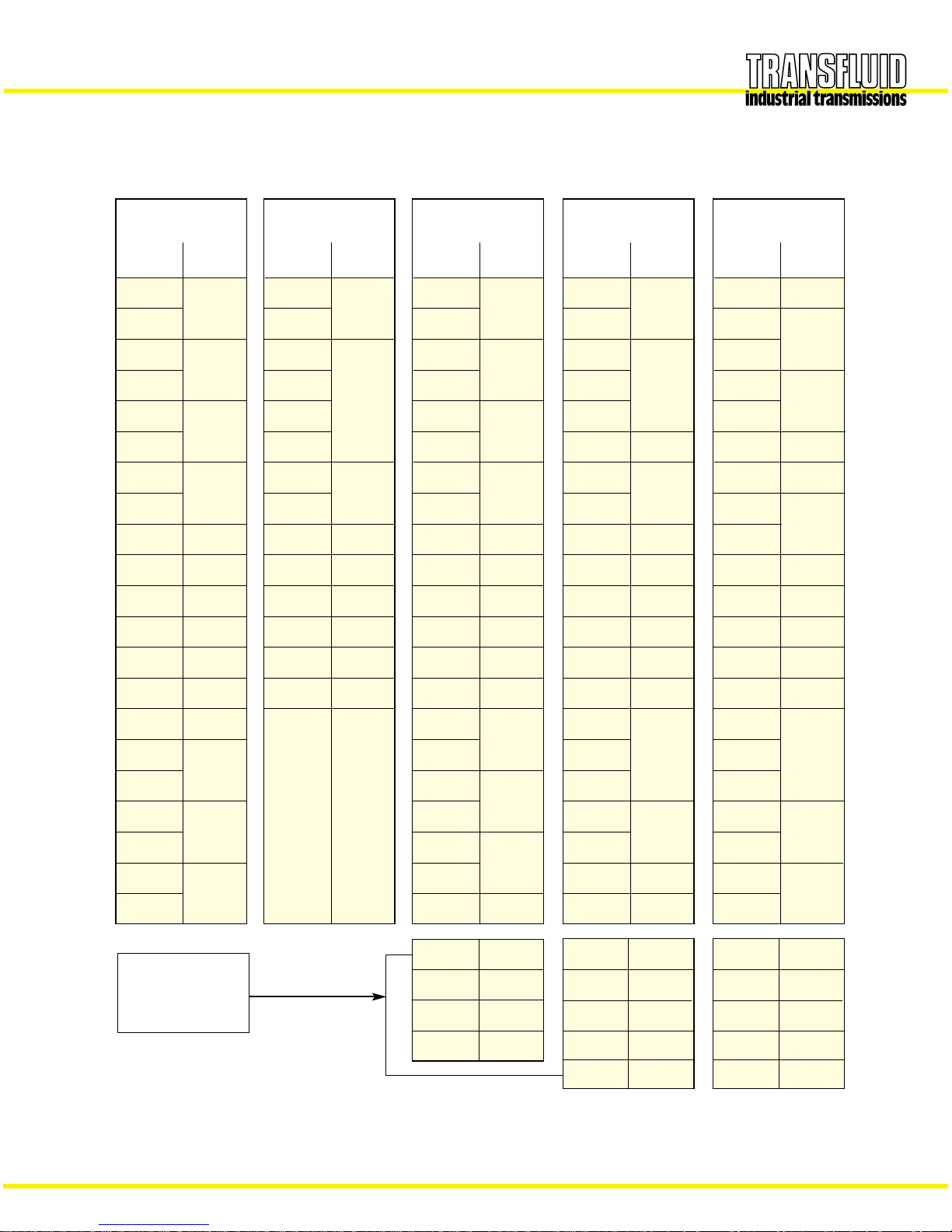
SELECTION
SELECTION CHART
The chart below may be used to select a unit size from the
horsepower and input speed.If the selection point falls on the line
dividing one size from the other, select the larger size with a
proportionally reduced oil fill.
GENERAL REFERENCE HORSEPOWER CHART
HP
kW
HORSEPOWER
INPUT SPEED RPM
THE CURVES SHOW THE POWER CAPACITY OF COUPLING IN REFERENCE TO INPUT SPEED
FLUID COUPLING SELECTION
8
MOTOR
FRAME
143T
22.275
(0.875)
145T
182T
28.575
(1.125)
184T
213T
34.925
(1.375)
215T
254
41.275
(1.625)
256T
284T
47.625
(1.875)
284TS
41.275
(1.625)
286T
47.625
(1.825)
286TS
41.275
(1.625)
324T
53.975
(2.125)
324TS
47.625
(1.875)
53.975
(2.125
60.325
(2.375)
73.025
(2.875)
85.725
(3.375)
326T
364T
365T
404T
405T
444T
445T
SHAFT DIA.
mm (inch)
1800 rpm
HP
1
6K
1.5 - 2
3
7 K
5
7.5
8K
10
15
9K
20
25 11 K
--
30 12 K
--
40 12 K
--
13 K
15 K
17 K
19 K
50
60
75
100
125
150
200-250
COUPLING
1200 rpm
HP
0.75
7 K
1
1.5
8 K
2
3
9K
5
7.5
11 K
10
15 12 K
--
20 13 K
--
25 13 K
--
15 K
17 K
19 K
21 K
30
40
50
60
75
100
125
COUPLING
900 rpm
HP
0.5
7 K
8 K
0.75
1
9 K
1.5
2
11 K
3
5
12 K
7.5
10
13 K
--
15 15 K
--
20 17 K
--
17 K
19 K
21 K
25
30
40
50
60
75
100
COUPLING
3600 rpm
HP
1.5
6 K
2
3
5
7.5
7 K
10 - 15
15 - 20
8K
20 - 25
--
30 9K
--
40 9K
--
50 9K
--
COUPLING
NON - STANDARD
MOTOR
400
600
21 K
24 K
958
27 K
1360
29 K
270 24 K
400
598
27 K
29 K
1088
34 K
1350
D 34 K
150 24 K
220
350
27 K
29 K
600
34 K
1000
D 34 K
SELECTION T ABLE
Fluid couplings for standard electric motor
max max
max
General note: The fluid coupling size is tied to the motor shaft dimensions
(1) Special version, 24 hours/day service
(1)
 Loading...