

Microchannel
REMOTE AIR-COOLED CONDENSER
WITH ELECTRONICALLY COMMUTATED AXITOP MOTORS
Technical Bulletin: MXCE_002_091815
Products that provide lasting solutions.

Microchannel Remote Air-Cooled Condenser
Krack’s new Microchannel Remote Air-Cooled Condenser incorporates
a new patented modular assembly.
Krack, a Hussmann
Corporation brand,
has a long tradition
of leadership and
n Smaller size and less weight reduces cost in the building construction.
n The new coil has less internal volume resulting in a significant reduction
in refrigerant charge. Less refrigerant is environmentally friendly.
n Coil slabs are easily replaced from the rear of the unit.
product innovation
in the refrigeration
industry.
Environmentally Friendly Benefits
n Reduced Coil Internal Volume - Resulting in a significant reduction
in condenser operating and flooding charge.
n AxiTop Fan Diffuser - Compared to a standard fan blade and guard,
the AxiTop increases CFM 10% while lowering energy consumption 5%.
n EC Motor - Continuously variable speed operation provides vastly
greater energy savings than traditional fan cycling.
California Energy Commission
n Models compliant with CEC Title 24 are offered.
Table of Contents
Benefits and Features 1
System Selections 2
Model Key 2
Applications 3
Performance Data 4
California Energy Commission Title 24 Performance Data 5
Dimensional Data
- Standard Model 6
- Receiver Model 7
Receiver Data 8
Control System 8
Electrical Data 9
Control Panel Nomenclature 10
Condenser Control Panel 1 1
MICROCHANNEL REMOTE AIR-COOLED CONDENSER
Specifications subject to change without notice.
Microchannel Remote Air-Cooled Condenser
US
Benefits and Features
REMOTE AIR-COOLED CONDENSER
Patented Microchannel Condenser Modular
Assembly Design (Patent #6988538)
n Arranged for vertical air discharge.
n Multi-fan sections compartmented to allow
individual fan cycling while preventing off-fan
“windmilling.”
n Removable end panel for clean out and service
access.
Corrosion Resistant
n All models employ mill galvanized steel fan
sections and coil side baffles.
n Legs are heavy mill gauge galvanized steel.
n Corrosion resistance is improved with an all aluminum
microchannel coil, reducing the chance for galvanic
corrosion that exists on traditional copper tube and
aluminum fin coils. Additionally, the microchannel
tubes are coated with a sacrificial metallic layer that
is less noble than the tube, fin, and braze material.
PROTECTIVE COVER PANELS
Electronically Commutated Motors
n Continuously variable speed operation results
in significant savings in energy usage.
n More accurate airflow control prevents wear and
tear on the coil, extending condenser life.
n Integral phase-loss, locked rotor, and overheat
protection.
n Electrical enclosures are protected with labyrinth
seals, gaskets, and liquid tight connections for
all-weather operation.
COMPACT DESIGN
n Lighter weight.
- Up to 35% weight reduction compared to
traditional condenser design.
n Modular construction and fewer parts.
- Available in 2 to 14 fan models.
AXITOP FAN DIFFUSER
n Design provides a clean path for air to exit
and reduces turbulence.
n Compared to a standard fan blade and guard, the
AxiTop increases CFM 10% while lowering energy
consumption 5%.
n Sound levels are also reduced thanks to the
lowered turbulence.
OPTIONAL FEATURES
n Electro-Fin coated coils.
n Mounted receiver.
n Reusable air filter.
n Module isolation ball valves.
Versatile Fan Control Methods
n Electronic relay boards.
n Temperature or pressure speed controls.
n No controls.
Replaceable High Efficiency Coil
n Extruded aluminum microchannel coil construction
increases coil efficiency, while reducing refrigerant
operating charge, unit weight and footprint.
n Unit design allows for coil replacement from rear
of unit.
MICROCHANNEL REMOTE AIR-COOLED CONDENSER
1
Specifications subject to change without notice.
Microchannel Remote Air-Cooled Condenser
EVAPORATOR
TEMP (˚F)
-40
-30
-20
-10
0
5
10
15
20
25
30
40
50
90
1.66
1.57
1.49
1.42
1.36
1.33
1.31
1.28
1.26
1.24
1.22
1.18
1.14
100
1.73
1.62
1.53
1.46
1.40
1.37
1.34
1.32
1.29
1.27
1.25
1.21
1.17
110
1.80
1.68
1.58
1.50
1.44
1.41
1.38
1.35
1.33
1.31
1.28
1.24
1.20
120
2.00
1.80
1.65
1.57
1.50
1.46
1.43
1.40
1.37
1.35
1.32
1.27
1.23
130
*
*
*
1.64
1.56
1.52
1.49
1.46
1.43
1.40
1.37
1.31
1.26
140
*
*
*
*
1.62
1.59
1.55
1.52
1.49
1.45
1.42
1.35
1.29
CONDENSING TEMPERATURE (˚F)
HERMETIC COMPRESSOR
EVAPORATOR
TEMP (˚F)
-30
-20
-10
0
10
20
30
40
50
90
1.37
1.33
1.28
1.24
1.21
1.17
1.14
1.12
1.09
100
1.42
1.37
1.32
1.28
1.24
1.20
1.17
1.15
1.12
110
1.47
1.42
1.37
1.32
1.28
1.24
1.20
1.17
1.14
120
*
1.47
1.42
1.37
1.32
1.28
1.24
1.20
1.17
130
*
*
1.47
1.41
1.36
1.32
1.27
1.23
1.20
140
*
*
*
1.47
1.42
1.37
1.32
1.28
1.24
CONDENSING TEMPERATURE (˚F)
OPEN COMPRESSOR
TABLE 1
TABLE 2
* Beyond the normal limits for single-stage compressor application.
* Beyond the normal limits for single-stage compressor application.
EVAPORATOR
TEMP (˚F)
-40
-30
-20
-10
0
5
10
15
20
25
30
40
50
90
1.66
1.57
1.49
1.42
1.36
1.33
1.31
1.28
1.26
1.24
1.22
1.18
1.14
100
1.73
1.62
1.53
1.46
1.40
1.37
1.34
1.32
1.29
1.27
1.25
1.21
1.17
110
1.80
1.68
1.58
1.50
1.44
1.41
1.38
1.35
1.33
1.31
1.28
1.24
1.20
120
2.00
1.80
1.65
1.57
1.50
1.46
1.43
1.40
1.37
1.35
1.32
1.27
1.23
130
*
*
*
1.64
1.56
1.52
1.49
1.46
1.43
1.40
1.37
1.31
1.26
140
*
*
*
*
1.62
1.59
1.55
1.52
1.49
1.45
1.42
1.35
1.29
CONDENSING TEMPERATURE (˚F)
HERMETIC COMPRESS
OR
TABLE 1
* Beyond the normal limits for single-stage compressor application.
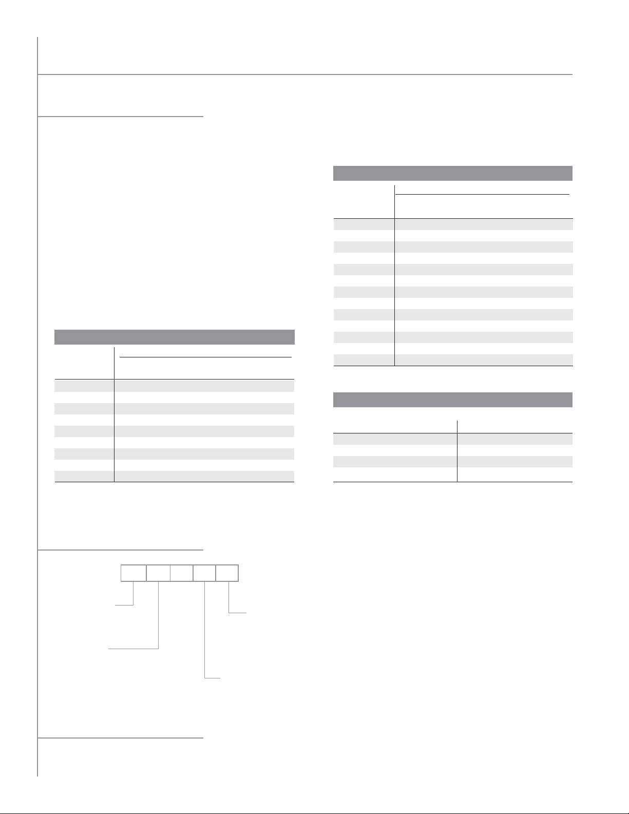
System Selections
THR - Total Heat of Rejection
n Condenser total heat of rejection (BTU/h) is the sum of the
evaporator refrigeration effect and the heat of compression
which varies with compressor type and operating conditions.
THR Calculation Method
n THR = Open Reciprocating Compressor Capacity
(BTU/h) + (2545 x BHP)
n THR = Suction Gas Cooled Hermetic Reciprocating
Compressor Capacity (BTU/h) + (3413 x kW)
THR Estimated Method
n THR may be estimated by multiplying the rated
compressor BTU/h capacity by the compressor operating
condition factor shown in Table 1 or 2.
Multiply result by altitude factor when applicable.
EVAPORATOR
TEMP (˚F)
-30
-20
-10
10
20
30
40
50
* Beyond the normal limits for single-stage compressor application.
Model Key
UNIT TYPE:
MX = Microchannel
FAN/MOTOR
COMBINATION:
H=1020 RPM 2.5 HP EC
0
CONDENSING TEMPERATURE (˚F)
90
1.37
1.33
1.28
1.24
1.21
1.17
1.14
1.12
1.09
MX H-06 M
TABLE 2
OPEN COMPRESSOR
100
1.42
1.37
1.32
1.28
1.24
1.20
1.17
1.15
1.12
110
120
1.47
1.42
1.47
1.37
1.42
1.32
1.37
1.28
1.32
1.24
1.28
1.20
1.24
1.17
1.20
1.14
1.17
130
*
TOTAL NUMBER OF FANS:
02 10
04 12
06 14
08
140
*
*
*
*
1.47
1.41
1.36
1.32
1.27
1.23
1.20
MOTOR VOLTAGE:
*
1.47
1.42
1.37
1.32
1.28
1.24
K= 208/230/3/60
M= 460/3/60
U= 380/3/50
TABLE 1
HERMETIC COMPRESSO
EVAPORATOR
TEMP (˚F)
-40
-30
-20
-10
0
5
10
15
20
25
30
40
50
* Beyond the normal limits for single-stage compressor application.
CONDENSING TEMPERATURE (˚F)
90
100
110
1.66
1.73
1.80
1.57
1.62
1.68
1.49
1.53
1.58
1.42
1.46
1.50
1.36
1.40
1.44
1.33
1.37
1.41
1.31
1.34
1.38
1.28
1.32
1.35
1.26
1.29
1.33
1.24
1.27
1.31
1.22
1.25
1.28
1.18
1.21
1.24
1.14
1.17
1.20
TABLE 3
ALTITUDE
FEET
1,000
2,000
3,000
4,000
FACTOR
1.02
1.05
1.07
1.10
FEET
5,000
6,000
7,000
8,000
120
2.00
1.80
1.65
1.57
1.50
1.46
1.43
1.40
1.37
1.35
1.32
1.27
1.23
R
130
*
*
*
1.64
1.56
1.52
1.49
1.46
1.43
1.40
1.37
1.31
1.26
FACTOR
1.12
1.15
1.17
1.24
140
*
*
*
*
1.62
1.59
1.55
1.52
1.49
1.45
1.42
1.35
1.29
MICROCHANNEL REMOTE AIR-COOLED CONDENSER
2
Specifications subject to change without notice.
Microchannel Remote Air-Cooled Condenser
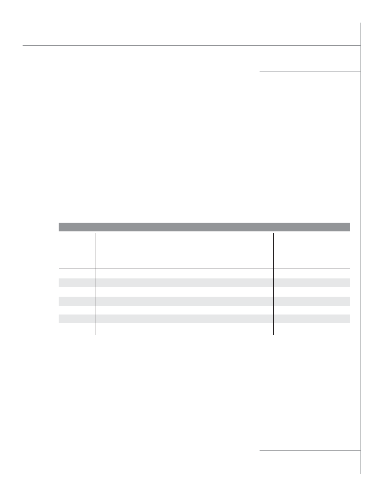
Applications
n Locate Condensers no closer than their width from walls
or other condensers. Avoid locations near exhaust fans,
plumbing vents, flues or chimneys.
n Parallel Condensers should be the same model resulting
in the same refrigerant side pressure drops. Compressor
discharge lines should have equal pressure drops to each
condenser.
n Condenser Refrigerant Charge for Summer conditions
are listed on the Performance Data Table. The additional
Winter Flooding charge required is difficult to predict
with fan cycling and is maximized with holdback; however,
the maximum additional refrigerant charge is also listed
on the Performance Data Table for Winter conditions
at -20˚F. The Summer operating and Winter maximum
flooding charge is substantially less than that required for
traditional tube and fin condensers due to the reduced
internal volume of the microchannel coils.
REFRIGERANT LINE CAPACITY DATA
COPPER
LINE
SIZE
O.D.
5/8
7/8
1-1/8
1-3/8
1-5/8
2-1/8
2-5/8
DISCHARGE LINE
R-404A R-407A R-134a
0.5 1.0 0.5 3.0 3.6 3.7 11.0 13.0 13.0
2.0 3.0 2.0 6.0 7.4 7.7 22.0 25.0 26.0
4.5 6.5 4.5 10.4 12.7 13.0 36.0 42.0 43.0
7.0 15.0 7.0 16.0 19.2 20.0 55.0 64.0 65.0
15.0 20.0 11.0 23.0 29.0 28.5 78.0 90.0 92.0
30.0 45.0 28.0 40.0 47.0 46.0 138.0 160.0 163.0
45.0 75.0 43.0 62.0 73.0 72.0 212.0 245.0 250.0
LINE CAPACITY IN TONS
n Receiver Capacity should be sized to store condenser
summer charge, plus the condenser low ambient
allowance, plus the evaporator charge, plus an allowance
for piping and heat reclaim coil charges.
n Compressor Discharge lines should be sized to minimize
pressure drops and maintain oil return gas velocities. Each
connection should be looped to the top of the condenser.
n Gravity Liquid Drain Lines should drop from each outlet as
low as possible before headering or running horizontally.
Pitch downhill to receiver.
LBS. OF REFRIGERANT
CONDENSER TO RECEIVERCOMPRESSOR
LIQUID LINE 100’
R-404A R-407A R-134a
LIQUID PER 100’
OF LENGTH
R-404A R-407A R-134a
Capacity is compressor suction tons for application between -40ºF and +40ºF suction at condensing temperatures between 80ºF and 120ºF sat.
For multiple or unloading compressor application, the vertical discharge riser from the compressor may need to be one size smaller.
This table data is only to be used as a guide. For exact values, please calculate to your specific job line lengths and design pressure/temp values
MICROCHANNEL REMOTE AIR-COOLED CONDENSER
using ASHRAE handbook or ARI refrigerant tables.
3
Specifications subject to change without notice.
 Loading...