

Krack MK14A-121 Installation Manual

M
M
M
e
e
dii
a
M
d
O
K//
K
u
u
C
C
O
M
M
m
m
o
o
p
err
p
e
a
V
V
Prr
P
oll
o
a
a
n
d
n
d
S
errii
S
e
offiill
o
err
e
tii
t
s
s
n
n
e
e
e
e
g
g
s
s
U
U
niitt
n
n
IIn
M
MK/MV-Medium Profile Series Unit Coolers (E206993_B)
stt
M
s
allll
a
a
n
a
n
attii
a
u
all
u
a
o
o
n
n

TABLE OF CONTENTS
1 RECEIPT OF EQUIPMENT _______________________________________________________3
1.1 INSPECTION ________________________________________________________________3
1.2 LOSS OF GAS HOLDING CHARGE _____________________________________________3
2 UNIT INFORMATION AND DIMENSIONS__________________________________________3
2.1 MODELS COVERED __________________________________________________________3
2.2 UNIT DIMENSIONS __________________________________________________________4
3 UNIT LOCATION AND MOUNTING _______________________________________________4
3.1 UNIT LOCATION_____________________________________________________________4
3.2 MOUNTING _________________________________________________________________4
4 PIPING INSTALLATION _________________________________________________________4
4.1 DRAIN LINE_________________________________________________________________4
4.2 REFRIGERATION PIPING _____________________________________________________5
4.3 EVACUATION AND LEAK TEST _______________________________________________5
4.4 HOT GAS DEFROST PIPING ___________________________________________________6
4.5 REFRIGERANT DISTRIBUTOR NOZZLES _______________________________________8
4.6 EXPANSION VALVE ________________________________________________________10
5 ELECTRICAL__________________________________________________________________12
5.1 FIELD WIRING _____________________________________________________________12
5.2 ELECTRICAL DATA_________________________________________________________12
5.3 AIR DEFROST SEQUENCE OF OPERATION_____________________________________13
5.4 ELECTRIC DEFROST SEQUENCE OF OPERATION_______________________________13
5.5 HOT GAS DEFROST SEQUENCE OF OPERATION _______________________________18
6 START UP _____________________________________________________________________21
6.1 PRE-STARTUP______________________________________________________________21
6.2 OPERATION CHECKOUT ____________________________________________________21
7 REPLACEMENT PARTS LIST ___________________________________________________22
8 PREVENTATIVE MAINTENANCE _______________________________________________23
9 TROUBLESHOOTING CHART___________________________________________________23
MK/MV – Medium Profile Series Unit Coolers (E206993_B)
1

TABLE OF CONTENTS
CHARTS
Table 1 UNIT DIMENSIONS............................................................................................................................................... 4
Table 2 SUCTION CONNECTION...................................................................................................................................... 7
Table 3 MK MEDIUM TEMPERATURE – AIR DEFROST............................................................................................... 8
Table 4 MK ELECTRIC OR GAS DEFROST...................................................................................................................... 9
Table 5 MV LOW TEMPERATURE/HIGH VELOCITY - ELECTRIC DEFROST...........................................................9
Table 6 MK SERIES – AIR DEFROST.............................................................................................................................. 10
Table 7 MK SERIES – ELECTRIC DEFROST.................................................................................................................. 11
Table 8 MV SERIES – LOW TEMPERATURE – HIGH VELOCITY.............................................................................. 11
Table 9 MK MOTOR AMPS – 1/4 HP MOTOR................................................................................................................ 12
Table 10 MV MOTOR AMPS – 1/3 HP MOTOR.............................................................................................................. 12
Table 11 MK & MV EC AMPS – 1/3 HP MOTOR............................................................................................................ 12
Table 12 MK HEATER AMPS ........................................................................................................................................... 12
Table 13 MV HEATER AMPS ........................................................................................................................................... 13
Table 14 REPLACEMENT PARTS LIST........................................................................................................................... 22
Table 15 TROUBLESHOOTING CHART......................................................................................................................... 23
FIGURES
Figure 1 UNIT DIMENSIONS............................................................................................................................................. 4
Figure 2 (H) HGE - 3 PIPE HOT GAS COIL WITH ELECTRIC DRAIN PAN DEFROST PI PI NG................................. 6
Figure 3 (G)HGG - 3 PIPE HOT GAS COIL WITH HOT GAS DRA IN PAN DEFROST PIPING.................................... 6
Figure 4 (K) KGE - 2 PIPE REVERSE CYCLE KOOL GAS COIL WITH ELECTR. DP DEFROST PIPING................. 7
Figure 5 (K) KGG - 2 PIPE REVERSE CYCLE KOOL GAS COIL WITH KOOL GAS DP DEFR OST PIPING............. 7
Figure 6 AIR DEFROST WIRING 1 PH.............................................................................................................................13
Figure 7 AIR DEFROST WIRING 3 PH............................................................................................................................. 13
Figure 8 ELECTRIC DEFROST WIRING 208-230/60/1................................................................................................... 15
Figure 9 ELECTRIC DEFROST WIRING 208-230/60/3................................................................................................... 15
Figure 10 ELECTRIC DEFROST WIRING 460/60/3.........................................................................................................15
Figure 11 MULTIPLE UNIT COOLERS, ELECTRIC DEFROST 460/60/3.....................................................................17
Figure 12 MULTIPLE UNIT COOLERS, ELECTRIC DEFROST 208-230/60/3.............................................................. 18
Figure 13 (H) HGE - 3 PIPE HOT GAS COIL AND ELECTRIC DRAIN PAN DEFROST WIRING.............................19
Figure 14 (G) HGG - 3 PIPE HOT GAS COIL AND HOT GAS DRAIN PAN DEFROST WIRING...............................19
Figure 15 (P) KGE - 2 PIPE KOOL GAS COIL AND ELECTRIC DRAIN PAN DEFROST WIRING...........................20
Figure 16 (K) KGG - 2 PIPE KOOL GAS COIL WITH KOOL GAS DRAIN PAN DEFROST WIRING.......................20
MK/MV – Medium Profile Series Unit Coolers (E206993_B)
2
1 RECEIPT OF EQUIPMENT
1.1 INSPECTION
All equipment should be carefully checked for damage or shortages as soon as it is received. Each
shipment should be carefully checked against the bill of lading. If any damage or shortage is evident, a
notation must be made on the delivery receipt before it is signed and a claim should then be filed against
the freight carrier.
1.2 LOSS OF GAS HOLDING CHARGE
Each unit cooler is leak tested, evacuated to remove moisture and then shipped with a gas holding
charge. Absence of this charge may indicate a leak has developed in transit. The system should not be
charged with refrigerant until it is verified that there is no leak or the source of the leak is located.
2 UNIT INFORMATION AND DIMENSIONS
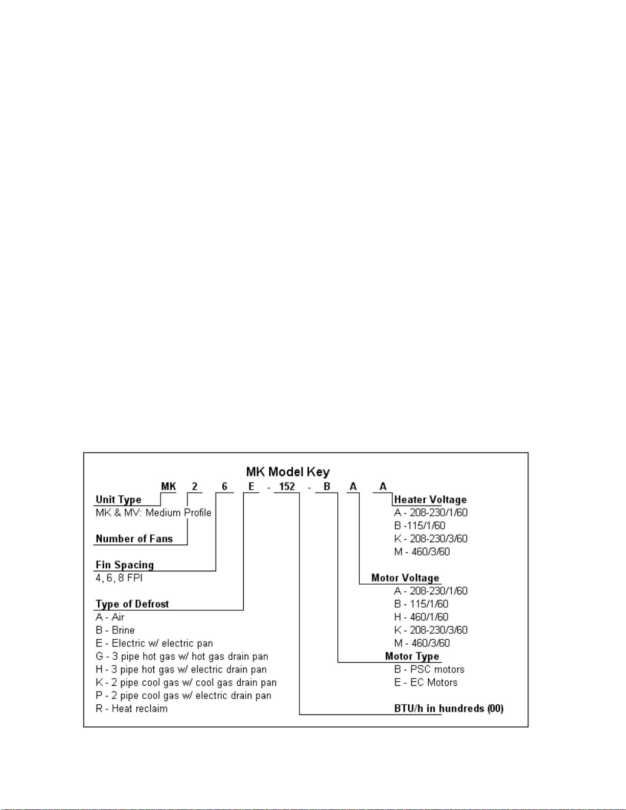
2.1 MODELS COVERED
MK Series medium profile unit coolers.
MV Series medium profile unit coolers - low temperature.
The MK and MV series are designed for walk-in coolers with ceiling heights of 10 to 14 feet that require
high airflow. MK/MV unit coolers draw air through the coil and discharge it into the room via the unit
fans.
The MK series handles medium to low temperature requirements and has three defrost options – air,
electric and hot gas. The MV series is designed for low temperatures requiring extra high air discharge
velocities. The MV unit coolers are only available with electric defrost.
MK/MV – Medium Profile Series Unit Coolers (E206993_B)
3
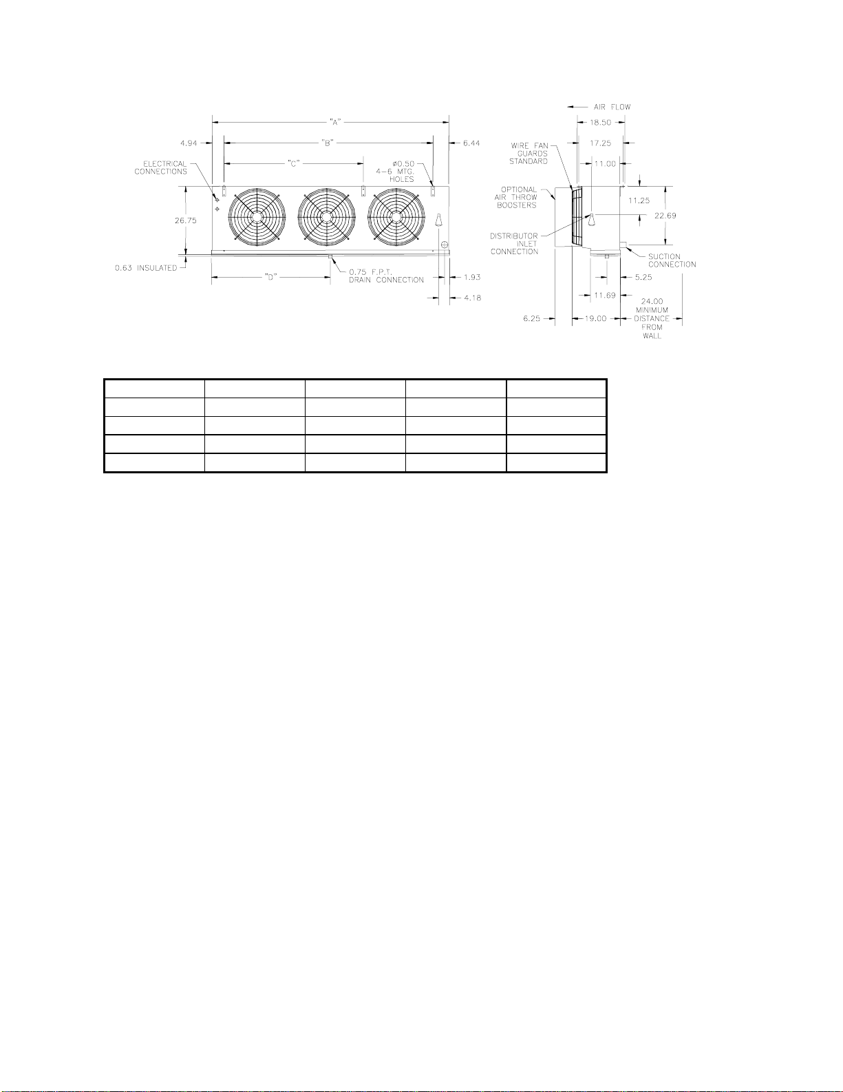
2.2 UNIT DIMENSIONS
Figure 1
Table 1 UNIT DIMENSIONS
Unit Size “A” “B” “C” “D”
UNIT DIMENSIONS
1 FAN
2 FAN
3 FAN
4 FAN
38.375 27.00 _ 19.188
63.375 54.00 _ 32.688
92.375 81.00 54.00 46.188
119.375 108.00 54.00 59.688
3 UNIT LOCATION AND MOUNTING
3.1 UNIT LOCATION
Unit coolers must be located to provide good air circulation to all areas of the cooler. The unit cooler
should be positioned to blow away from the wall and directed down an aisle rather than into and through
shelves. For best performance it is desirable to arrange the air discharge toward the door of the cooler to
minimize the entrance of warm moist air when the door is open. Light fixtures, shelving and product
boxes must be located so that they do not block the air intake or air discharge from the unit cooler.
IMPORTANT:
The coil face must be located a minimum of 24” from walls to assure unrestricted air intake.
3.2 MOUNTING
The unit cooler should be suspended with 3/8” diameter hanger rods or flush mounted against the ceiling
using 3/8” minimum lag screws with flat washers. Rods should have double nuts on the top and bottom.
Adequate support must be provided to hold the weight of the unit.
The unit must be level in all directions to insure proper drainage of the condensate. Suspended units
must have sufficient clearance above for cleaning the top.
4 PIPING INSTALLATION
4.1 DRAIN LINE
The drain line should be as short and as steeply pitched as possible with a minimum of ¼” drop per
running foot. A drain line trap should be installed to prevent warm moist air from migrating through the
drain line. If the temperature surrounding the drain line and trap is below freezing (32°) it must be
wrapped with a drain line heater and insulation. Be sure to also wrap the drain pan coupling. The drain
MK/MV – Medium Profile Series Unit Coolers (E206993_B)
4

line heater must be energized continuously. Be sure to follow the manufacturer’s recommendation when
installing the drain line heat tape.
A union at the drain connection in the drain pan is recommended for ease of installation and future
servicing. The union should be located as close to the drain pan as possible. Use two wrenches when
tightening to prevent the drain fitting from twisting and damaging the unit.
Long runs of drain line, i.e. more than a few feet should be supported by hangers to avoid damage to the
drain pan.
4.2 REFRIGERATION PIPING
System design must conform to all local and national codes, laws and regulations applying to the site of
installation. In addition the safety code for mechanical refrigeration, ASME B31.5, should be followed
as a guide to safe installation and operation practice.
Refrigerant line sizes and piping techniques should be obtained from the ASHRAE guide or equivalent
reference. Under no circumstances should the refrigerant connection size of the unit be used as the basis
for sizing the lines.
The horizontal suction line should slope away from the unit cooler toward the compressor. Vertical
suction risers may require a trap at the bottom of the riser for proper oil return.
When connecting multiple unit coolers in series using a common suction line, the branch suction lines
must enter the top of the common suction line. The branch lines must be sized for the evaporator
capacity and the common suction line to be sized for the total system capacity.
For units with hot gas defrost refer to section 4.4 and figures 2 through 5 for piping arrangement.
Refer to section 4.5 for refrigerant distributor nozzle selection.
Refer to section 4.6 for expansion valve selection.
For Food Service installations – seal any joint between unit cooler and cooler wall with a sealant Listed
by the National Sanitation Foundation.
4.3 EVACUATION AND LEAK TEST
When all refrigeration connections have been completed, the entire system must be tested for leaks and
then evacuated. Refer to the instructions provided with your systems condensing unit for information on
performing the leak test and evacuation.
MK/MV – Medium Profile Series Unit Coolers (E206993_B)
5
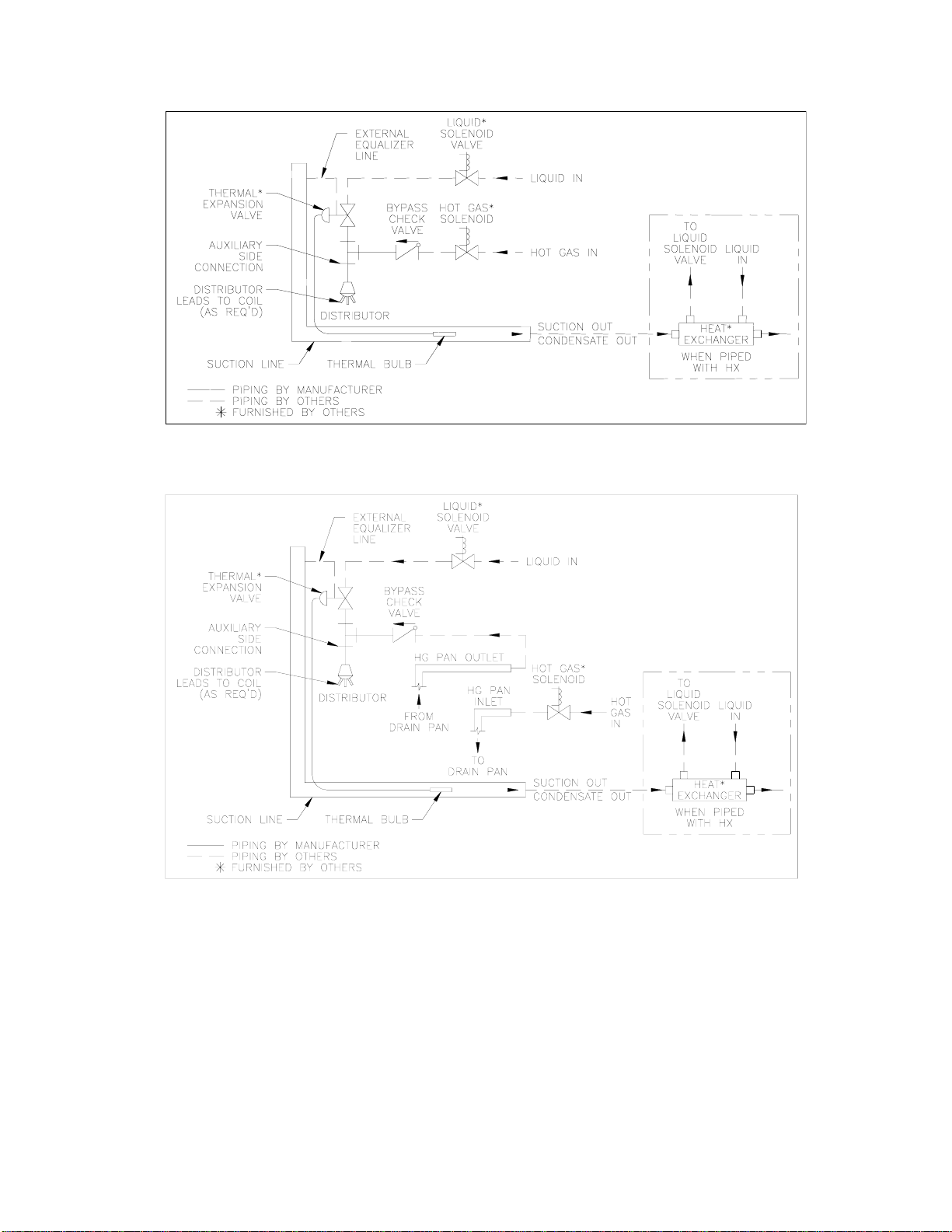
4.4 MK HOT GAS DEFROST PIPING
Figure 2 (H) HGE - 3 PIPE HOT GAS COIL WITH ELECTRIC DRAIN PAN DEFROST PIPING
Figure 3 (G)HGG - 3 PIPE HOT GAS COIL WITH HOT GAS DRAIN PAN DEFROST PIPING
MK/MV – Medium Profile Series Unit Coolers (E206993_B)
6

Figure 4 (K) KGE - 2 PIPE REVERSE CYCLE KOOL GAS COIL WITH ELECTR. DP DEFROST
PIPING
Figure 5 (K) KGG - 2 PIPE REVERSE CYCLE KOOL GAS COIL WITH KOOL GAS DP DEFROST
PIPING
Table 2 SUCTION CONNECTION
2, 3 CIRCUITS 4, 5 CIRCUITS 6,7,8,10,13,15 CIRCUITS 20 CIRCUITS
7/8” 1-1/8” 1-5/8” 2-1/8”
To identify number of circuits per model refer to tables 3, 4 and 5.
MK/MV – Medium Profile Series Unit Coolers (E206993_B)
7
 Loading...