


Levitor II
AIR-COOLED CONDENSER WITH
ELECTRONICALLY COMMUTATED AXITOP MOTORS
(Available for Fluid Cooler Applications)
Technical Bulletin: LEVE_001_083115
Products that provide lasting solutions.
Levitor II Air-Cooled Condenser
Table of Contents
Benefits and Features 1
System Selection 2
Levitor Application 3
Model Key 4
LAVH/LEVH Condenser Performance Data, One and Two Fans Wide 5
California Energy Commision (CEC) Title 24 7
LAVH/LEVH Performance Data - Title 24 7
Dimensional Drawings 8
Mounted Receivers 9
Mounted Receiver Diagrams 10
Control Panel Nomenclature 12
Standard Fan Control Arrangements 13
Fan Speed Modulation 13
Low Ambient Controls 14
Wiring Diagram 15
LEVITOR II AIR-COOLED CONDENSER
Specifications subject to change without notice.
Rooftop condensers have to operate in some of the toughest
US
conditions imaginable. Temperature extremes result in
constant expansion and contraction of refrigerant tubes as
fans cycle and loads vary.
The consequences are costly: rapid tube wear results in
leaks, system breakdown and loss of costly refrigerant.
Levitor II Air-Cooled Condenser
Benefits and Features
The LEVITOR system addresses refrigerant coil wear
and leaks due to vibration and thermal stress.
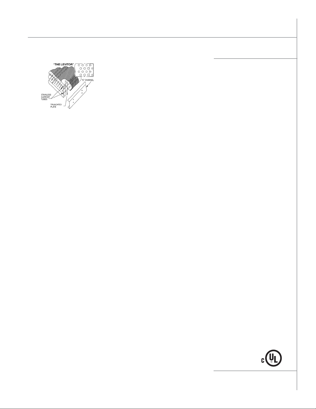
LEVITOR Coil Design Eliminates Refrigerant Tube Wear
Environmental concerns and spiraling cost of refrigerants have led to the
development of direct drive remote air-cooled condensers with the LEVITOR
coil support system. This innovative design uses dedicated stainless steel tubes
and a unique coil support system to isolate refrigerant tubes from the unit. Coil
support is transferred from the fins to the stainless tubes and truncated tube
plates which ride freely in “C” channels. Tubes expand and contract without
interference. The result, contact and friction wear are eliminated.
Quiet by Design
LEVITOR coil design does more than just eliminate tube wear.
Sound reduction is an added benefit. Unlike traditional air-cooled condensers,
fan and coil vibration are isolated from the cabinet, so it is not transmitted to
the unit frame and building supports.
AxiTop Fan Diffuser
n Design provides a clean path for air to exit
and reduces turbulence.
n Compared to a standard fan blade and guard, the
AxiTop increases CFM 10% while lowering energy
consumption 5%.
n Sound levels are also reduced thanks to the
lowered turbulence.
Exclusive 3-year Limited Warranty
n We’re so confident about our new suspended
coil design that it is protected by a 3-year limited
warranty on workmanship and material. It gives
you extra protection from premature tube wear.
See www.krack.com for complete warranty.
Computerized Circuiting
n Our computerized coil circuiting program is
designed to minimize the condenser refrigerant
charge and maximize subcooling. Every condenser
will be custom circuited to precisely meet your
application needs.
Modular Design
n Arranged for vertical or horizontal air discharge.
Multi-fan sections compartmented to allow
individual fan cycling while preventing off-fan
“windmilling”. Large clean-out access doors
standard.
Corrosion Resistant
n All models employ mill galvanized steel fan sections
and coil side baffles. Legs are heavy gauge mill
galvanized steel.
High Efficiency Coil
n Copper tubes are mechanically expanded into
corrugated full collared aluminum fins spaced 8,
10, or 12 per inch. Coils are helium leak and pressure
tested with 400 psig. dry air, shipped pressurized
with dry nitrogen.
n Optional fin materials are copper or polyester
coated aluminum.
n Optional electrofin or heresite coil coatings
available.
n Multi-circuiting available.
Electronically Commutated Motors
n Continuously variable speed operation results in
significant savings in energy usage.
n More accurate airflow control prevents wear and
tear on the coil, extending condenser life.
n Integral phase-loss, locked rotor, and overheat
protection.
n Electrical enclosures are protected with labyrinth
seals, gaskets, and liquid tight connections for
all-weather operation.
Versatile Control Methods
n Temperature or pressure speed control.
n Electronic relay boards.
n No controls.
LEVITOR II AIR-COOLED CONDENSER
Specifications subject to change without notice.
1

Levitor II Air-Cooled Condenser
EVAPORATOR
TEMP (˚F)
-40
-30
-20
-10
0
5
10
15
20
25
30
40
50
90
1.66
1.57
1.49
1.42
1.36
1.33
1.31
1.28
1.26
1.24
1.22
1.18
1.14
100
1.73
1.62
1.53
1.46
1.40
1.37
1.34
1.32
1.29
1.27
1.25
1.21
1.17
110
1.80
1.68
1.58
1.50
1.44
1.41
1.38
1.35
1.33
1.31
1.28
1.24
1.20
120
2.00
1.80
1.65
1.57
1.50
1.46
1.43
1.40
1.37
1.35
1.32
1.27
1.23
130
*
*
*
1.64
1.56
1.52
1.49
1.46
1.43
1.40
1.37
1.31
1.26
140
*
*
*
*
1.62
1.59
1.55
1.52
1.49
1.45
1.42
1.35
1.29
CONDENSING TEMPERATURE (˚F)
HERMETIC COMPRESSOR
TABLE 1
* Beyond the normal limits for single-stage compressor application.
EVAPORATOR
TEMP (˚F)
-40
-30
-20
-10
0
5
10
15
20
25
30
40
50
90
1.66
1.57
1.49
1.42
1.36
1.33
1.31
1.28
1.26
1.24
1.22
1.18
1.14
100
1.73
1.62
1.53
1.46
1.40
1.37
1.34
1.32
1.29
1.27
1.25
1.21
1.17
110
1.80
1.68
1.58
1.50
1.44
1.41
1.38
1.35
1.33
1.31
1.28
1.24
1.20
120
2.00
1.80
1.65
1.57
1.50
1.46
1.43
1.40
1.37
1.35
1.32
1.27
1.23
130
*
*
*
1.64
1.56
1.52
1.49
1.46
1.43
1.40
1.37
1.31
1.26
140
*
*
*
*
1.62
1.59
1.55
1.52
1.49
1.45
1.42
1.35
1.29
CONDENSING TEMPERATURE (˚F)
HERMETIC COMPRESS
OR
FEET
1,000
2,000
3,000
4,000
FACTOR
1.02
1.05
1.07
1.10
FEET
5,000
6,000
7,000
8,000
FACTOR
1.12
1.15
1.17
1.24
ALTITUDE
EVAPORATOR
TEMP (˚F)
-30
-20
-10
0
10
20
30
40
50
90
1.37
1.33
1.28
1.24
1.21
1.17
1.14
1.12
1.09
100
1.42
1.37
1.32
1.28
1.24
1.20
1.17
1.15
1.12
110
1.47
1.42
1.37
1.32
1.28
1.24
1.20
1.17
1.14
120
*
1.47
1.42
1.37
1.32
1.28
1.24
1.20
1.17
130
*
*
1.47
1.41
1.36
1.32
1.27
1.23
1.20
140
*
*
*
1.47
1.42
1.37
1.32
1.28
1.24
CONDENSING TEMPERATURE (˚F)
OPEN COMPRESSOR
TABLE 1
TABLE 2
TABLE 3
* Beyond the normal limits for single-stage compressor application.
* Beyond the normal limits for single-stage compressor application.
EVAPORATOR
TEMP (˚F)
-40
-30
-20
-10
0
5
10
15
20
25
30
40
50
90
1.66
1.57
1.49
1.42
1.36
1.33
1.31
1.28
1.26
1.24
1.22
1.18
1.14
100
1.73
1.62
1.53
1.46
1.40
1.37
1.34
1.32
1.29
1.27
1.25
1.21
1.17
110
1.80
1.68
1.58
1.50
1.44
1.41
1.38
1.35
1.33
1.31
1.28
1.24
1.20
120
2.00
1.80
1.65
1.57
1.50
1.46
1.43
1.40
1.37
1.35
1.32
1.27
1.23
130
*
*
*
1.64
1.56
1.52
1.49
1.46
1.43
1.40
1.37
1.31
1.26
140
*
*
*
*
1.62
1.59
1.55
1.52
1.49
1.45
1.42
1.35
1.29
CONDENSING TEMPERATURE (˚F)
HERMETIC COMPRESS
OR
EVAPORATOR
TEMP (˚F)
-30
-20
-10
0
10
20
30
40
50
90
1.37
1.33
1.28
1.24
1.21
1.17
1.14
1.12
1.09
100
1.42
1.37
1.32
1.28
1.24
1.20
1.17
1.15
1.12
110
1.47
1.42
1.37
1.32
1.28
1.24
1.20
1.17
1.14
120
*
1.47
1.42
1.37
1.32
1.28
1.24
1.20
1.17
130
*
*
1.47
1.41
1.36
1.32
1.27
1.23
1.20
140
*
*
*
1.47
1.42
1.37
1.32
1.28
1.24
CONDENSING TEMPERATURE (˚F)
OPEN COMPRESSOR
TABLE 1
TABLE 2
* Beyond the normal limits for single-stage compressor application.
* Beyond the normal limits for single-stage compressor application.
System Selection
THR Total Heat of Rejection
n Condenser total heat of rejection (BTU/h) is the sum of the evaporator refrigeration effect and the heat
of compression which varies with compressor type and operating conditions.
THR Calculation Method
n THR = Open Reciprocating Compressor Capacity
(BTU/h) + (2545 x BHP)
n THR = Suction Gas Cooled Hermetic Reciprocating
Compressor Capacity (BTU/h) + (3413 x kW)
THR Estimated Method
n THR may be estimated by multiplying the rated
compressor BTU/h capacity by the compressor
operating condition factor shown in Table 1 or 2.
Multiply result by altitude factor when applicable.
EVAPORATOR
TEMP (˚F)
* Beyond the normal limits for single-stage compressor application.
Multi-Circuit Selection
n
Condenser coils may be divided into several individual refrigeration circuits or systems; each sized for a specific refrigerant, THR
capacity and TD. Systems are tagged for identification from left to right; facing the connection end. Avoid multi-circuiting with
3-row condensers. Add excess circuits to low TD sections next to high TD sections. Add excess circuits to outboard sections.
COMP
NOM
HP
6
9
10
12
Selection
n LAVH-13410 Rated at THR of 430.7 MBH with R-404A
at 15°F TD. LAVH-13410 Unit lists 34 Circuits.
n Sample Calculation: THR Req’d./Circuit = 426304 ÷ 34 = 12538.
LAVH-13410 = 430700 ÷ 34 = 12668 (Available THR/Circuit).
n Circuits Req’d. = Select THR ÷ THR/Circuit.
Example: 56460 ÷ 12668 = 4.5 Circuits.
n Assign Number of Circuits System and System Number Left to Right.
Actual TD = (Circuits Req’d ÷ Assign Circuits) x Design TD.
Example: 4.5 ÷ 4 x 15 = 16.9.
-30
-20
-10
0
10
20
30
40
50
REF
134a
404A
404A
22
DESIGN
90
1.37
1.33
1.28
1.24
1.21
1.17
1.14
1.12
1.09
SAMPLE CALCULATION:
TD
°F
15
10
10
15
SAT
SUCT
°F
+20
-20
-20
+20
CONDENSING TEMPERATURE (˚F)
100
1.42
1.37
1.32
1.28
1.24
1.20
1.17
1.15
1.12
SAT
COND
110
105
105
110
TABLE 2
OPEN COMPRESSOR
110
1.47
1.42
1.37
1.32
1.28
1.24
1.20
1.17
1.14
NET
°F
BTU/h
40090
45900
50640
104000
120
*
1.47
1.42
1.37
1.32
1.28
1.24
1.20
1.17
95°F AMBIENT-SUCTION COOLED SEMI-HERMETIC RECIPROCATING COMPRESSORS
COMPRESSOR RATING
MOTOR MOTOR
kW
4.3
8.1
9.6
9.7
130
*
*
1.47
1.41
1.36
1.32
1.27
1.23
1.20
BTU/h
14676
27645
32765
33106
140
*
*
*
1.47
1.42
1.37
1.32
1.28
1.24
TOTAL
BTU/h
54,766
73,545
83,405
137,106
EVAPORATOR
=
=
=
=
90
1.66
1.57
1.49
1.42
1.36
1.33
1.31
1.28
1.26
1.24
1.22
1.18
1.14
FACTOR
1.02
1.05
1.07
1.10
°FTD
SELECT
THR
56460
110318
125108
134418
426304
R-404A - 1.00
R-22 - 1.02
R-134a - 0.97
TEMP (˚F)
-40
-30
-20
-10
0
5
10
15
20
25
30
40
50
* Beyond the normal limits for single-stage compressor application.
FEET
1,000
2,000
3,000
4,000
BASED ON R-404A AT 15
REF
FACTOR
÷
0.97
÷
1.00
÷
1.00
÷
1.02
FACTOR
x
x
x
x
TD
1.0
1.5
1.5
1.0
UNIT THR REQ’D
TABLE 1
HERMETIC COMPRESSO
CONDENSING TEMPERATURE (˚F)
100
110
120
1.73
1.80
2.00
1.62
1.68
1.80
1.53
1.58
1.65
1.46
1.50
1.57
1.40
1.44
1.50
1.37
1.41
1.46
1.34
1.38
1.43
1.32
1.35
1.40
1.29
1.33
1.37
1.27
1.31
1.35
1.25
1.28
1.32
1.21
1.24
1.27
1.17
1.20
1.23
R
130
*
*
*
1.64
1.56
1.52
1.49
1.46
1.43
1.40
1.37
1.31
1.26
TABLE 3
ALTITUDE
CAP
PER
CIRCUIT
12668
12668
12668
12668
REF FACTOR
CIRCUIT
REQ’D
4.5
8.7
9.9
10.6
FEET
5,000
6,000
7,000
8,000
#
CIR
4
10
10
10
34
SYSTEM
NUMBER
L TO R
1
2
3
4
TD FACTOR
10°F - 1.50
15°F - 1.00
20°F - 0.75
25°F - 0.60
FACTOR
ACTUAL
1.12
1.15
1.17
1.24
16.9
15.9
140
*
*
*
*
1.62
1.59
1.55
1.52
1.49
1.45
1.42
1.35
1.29
TD
°F
8.7
9.9

Levitor II Air-Cooled Condenser
Levitor Application
Locate Condensers no closer than their width from
walls or other condensers. Avoid locations near
exhaust fans, plumbing vents, flues, or chimneys.
Parallel Condensers should be the same models
resulting in the same refrigerant side pressure drops.
Compressor discharge lines should have equal
pressure drops to each condenser.
Summer Charge based on 25% of condenser volume
with 90˚F liquid. Multiply by 1.1 for R-407A.
Winter Charge based on 90% of condenser volume
with -20˚F liquid. Multiply by 1.08 for R-407A.
Receiver Capacity should be sized to store condenser
summer charge, plus the condenser low ambient
allowance, plus the evaporator charge, plus an
allowance for piping and heat reclaim coil charges.
Compressor Discharge lines should be sized to
minimize pressure drops and maintain oil return gas
velocities. Each connection should be looped to the
top of the condenser.
Gravity Liquid Drain Lines should drop from each
outlet as low as possible before headering or running
horizontally. Pitch downhill to receiver.
Off-Line Coil Sections will have refrigerant pressures
corresponding to the ambient. Check valves or
isolating valves should be installed in the liquid line
drains to prevent refrigerant migration and receiver
pressure loss.
See Installation and Operating instructions for piping, holdback, and speed control details.
CORRECTIONS FACTOR TABLE
MULTIPLY R-404A BY
REFRIGERANTS CAPACITY FACTOR SUMMER WINTER
R-404A 1.00 1.00 1.00
R-134A 0.97 1.17 1.11
R-410A 1.02 1.02 1.03
R-22 1.02 1.14 1.09
R-407A See R-407A Chart 1.10 1.08
R-407C 0.98 x R-407A 1.09 1.07
For units using 380/3/50, multiply capacity by 0.90.
CHARGE CORRECTION FACTOR
REFRIGERANT LINE CAPACITY DATA
COPPER
LINE
COMPRESSOR DISCHARGE LINE
SIZE
O.D.
5/8
7/8
1-1/8
1-3/8
1-5/8
2-1/8
2-5/8
n Capacity is compressor suction tons for application between -40°F and +40°F suction at condensing
temperatures between 80°F and 120°F sat.
n For multiple or unloading compressor applications, the vertical discharge riser from the compressor
may need to be one size smaller.
n This table data is only to be used as a guide. For exact values, please calculate to your specific job line
lengths and design pressure/temp values using ASHRAE handbook or ARI refrigerant tables.
R-404A
0.5
2.0
4.5
7.0
15.0
30.0
45.0
LINE CAPACITY IN TONS
R-407A
R-134A
1.0
3.0
6.5
15.0
20.0
45.0
75.0
11.0
28.0
43.0
0.5
2.0
4.5
7.0
CONDENSER TO RECEIVER
LIQUID LINE 100'
R-404A
3.0
6.0
10.4
16.0
23.0
40.0
62.0
R-407A
3.6
7.4
12.7
19.2
29.0
47.0
73.0
R-134A
3.7
7.7
13.0
20.0
28.5
46.0
72.0
LEVITOR II AIR-COOLED CONDENSER
Specifications subject to change without notice.
LBS. OF REFRIGERANT
LIQUID PER 100'
OF LENGTH
R-404A
11.0
22.0
36.0
55.0
78.0
138.0
212.0
R-407A
13.0
25.0
42.0
64.0
90.0
160.0
245.0
R-134A
13.0
26.0
43.0
65.0
92.0
163.0
250.0
3
Levitor II Air-Cooled Condenser
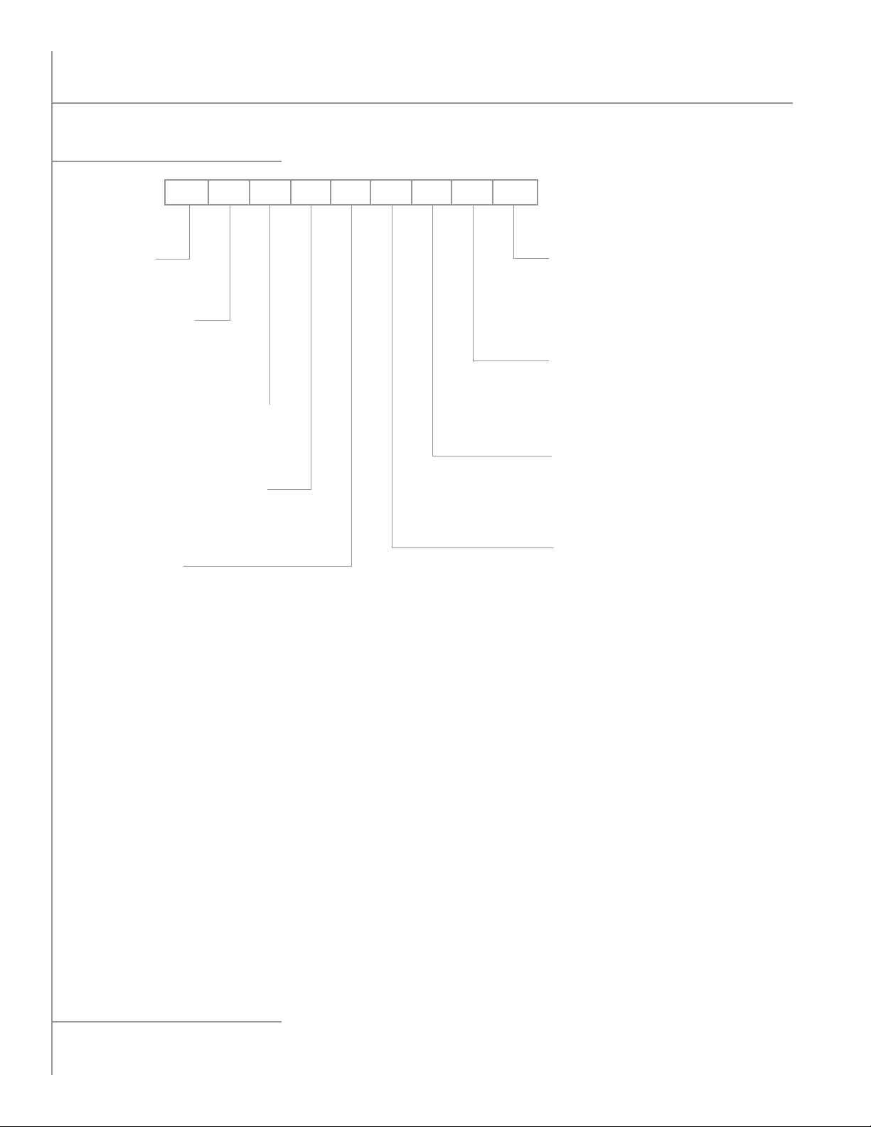
Model Key
L AVH12410 M
UNIT TYPE:
L=Levitor Condenser
TUBE DIAMETER:
A=3/8 O.D.
E=1/2 O.D.
FAN DISCHARGE DIRECTIONS:
H=Horizontal
V= Vertical
FAN/MOTOR COMBINATION:
H=1020 RPM 2.5 HP ECM
FANS WIDE: 1, 2
VOLTAGE:
K=208-230/3/60
M=460/3/60
U=380/3/50
FIN SPACING:
08 =8 FPI
10 = 10 FPI
12 = 12 FPI
ROWS DEEP:
2
3
4
FANS IN LINE:
1
2
3
4
5
6
LEVITOR II AIR-COOLED CONDENSER
4
Specifications subject to change without notice.