

Levitor II
AIR-COOLED CONDENSER
(Available for Fluid Cooler Applications)
Technical Bulletin: LEVC_001_083115
Products that provide lasting solutions.

Levitor II Air-Cooled Condenser
Table of Contents
Benefits and Features 1
System Selection 2
Levitor Application 3
Model Key 4
LAVE Performance Data, One and Two Fans Wide 5
LAVA Performance Data, One and Two Fans Wide 7
LAVC Performance Data, One and Two Fans Wide 9
LAVF Performance Data, One and Two Fans Wide 1 1
Electrical Motor AMP Data 13
Electrical Motor Watts Data 14
Dimensional Drawings 14
LAVB Performance Data, One and Two Fans Wide 15
Dimensional Drawings (for B Fan Models) 17
Mounted Receiver Diagrams 1 8
Low Ambient Controls 20
Mounted Receivers 20
Control Panel Nomenclature 2 1
Standard Fan Cycling/Control Arrangements 22
Fan Cycling Sequence 22
Wiring Diagrams 23
LEVITOR II AIR-COOLED CONDENSER
Specifications subject to change without notice.

Rooftop condensers have to operate in some of the toughest
US
conditions imaginable. Temperature extremes result in
constant expansion and contraction of refrigerant tubes as
fans cycle and loads vary.
The consequences are costly: rapid tube wear results inleaks,
system breakdown and loss of costly refrigerant.
Levitor II Air-Cooled Condenser
Benefits and Features
The LEVITOR system addresses refrigerant coil wear
and leaks due to vibration and thermal stress.
LEVITOR Coil Design Eliminates Refrigerant Tube Wear
Environmental concerns and spiraling cost of refrigerants have led to the
development of direct drive remote air-cooled condensers with the LEVITOR
coil support system. This innovative design uses dedicated stainless steel tubes
and a unique coil support system to isolate refrigerant tubes from the unit. Coil
support is transferred from the fins to the stainless tubes and truncated tube
plates which ride freely in “C” channels. Tubes expand and contract without
interference. The result, contact and friction wear are eliminated.
Quiet by Design
LEVITOR coil design does more than just eliminate tube wear.
Sound reduction is an added benefit. Unlike traditional air-cooled condensers,
fan and coil vibration are isolated from the cabinet, so it is not transmitted to
the unit frame and building supports.
Low Sound Quietor Fan
n The “swept-wing” blade design offers lower noise
levels at the same fan speed. For example, the
QUIETOR fan blade on a 575-rpm motor will be
much quieter (8 dBA) than the old 575-rpm fan.
n Lower noise condensers can translate into savings
for your customer by minimizing the need of costly
noise barriers.
n Quietor fan not available on 24” models.
Computerized Circuiting
n Our computerized coil circuiting program is
designed to minimize the condenser refrigerant
charge and maximize sub-cooling. Every condenser
will be custom circuited to precisely meet your
application needs.
Modular Design
n Arranged for vertical or horizontal air discharge.
Multi-fan sections compartmented to allow
individual fan cycling while preventing off-fan
“windmilling”. Large clean-out access doors
standard.
Corrosion Resistant
n All models employ mill galvanized steel fan sections
and coil side baffles. Legs are heavy gauge mill
galvanized steel.
High Efficiency Coil
n Copper tubes are mechanically expanded into
corrugated full collared aluminum fins spaced 8,
10, or 12 per inch. Coils are helium leak and pressure
tested with 400 psig dry air, shipped pressurized
with dry nitrogen.
n Optional fin materials are copper or polyester
coated aluminum.
n Optional electrofin or heresite coil coatings.
n Multi-circuiting available.
Direct Driven Propeller Fans
n Quiet multi-bladed propeller fans provide uniform
air distribution through the coil. Venturi fan orifices
optimize efficiency.
Weather Resistant Fan Motors
n Outdoor condenser motors designed with ball
bearings inherent overheat protection in each
phase; shaft slingers; enclosure, hardware, and
lubrication for all weather conditions. Each motor
lead is wired to terminals in an electrical enclosure.
n Inverter duty suitable motors are standard.
Versatile Fan Cycling Control Methods
n Temperature fan cycling.
n Pressure fan cycling.
n Temperature and pressure fan cycling.
n Electronic relay boards.
n Variable speed header end fans.
LEVITOR II AIR-COOLED CONDENSER
Specifications subject to change without notice.
1
Levitor II Air-Cooled Condenser
EVAPORATOR
TEMP (˚F)
-40
-30
-20
-10
0
5
10
15
20
25
30
40
50
90
1.66
1.57
1.49
1.42
1.36
1.33
1.31
1.28
1.26
1.24
1.22
1.18
1.14
100
1.73
1.62
1.53
1.46
1.40
1.37
1.34
1.32
1.29
1.27
1.25
1.21
1.17
110
1.80
1.68
1.58
1.50
1.44
1.41
1.38
1.35
1.33
1.31
1.28
1.24
1.20
120
2.00
1.80
1.65
1.57
1.50
1.46
1.43
1.40
1.37
1.35
1.32
1.27
1.23
130
*
*
*
1.64
1.56
1.52
1.49
1.46
1.43
1.40
1.37
1.31
1.26
140
*
*
*
*
1.62
1.59
1.55
1.52
1.49
1.45
1.42
1.35
1.29
CONDENSING TEMPERATURE (˚F)
HERMETIC COMPRESSOR
FEET
1,000
2,000
3,000
4,000
FACTOR
1.02
1.05
1.07
1.10
FEET
5,000
6,000
7,000
8,000
FACTOR
1.12
1.15
1.17
1.24
ALTITUDE
EVAPORATOR
TEMP (˚F)
-30
-20
-10
0
10
20
30
40
50
90
1.37
1.33
1.28
1.24
1.21
1.17
1.14
1.12
1.09
100
1.42
1.37
1.32
1.28
1.24
1.20
1.17
1.15
1.12
110
1.47
1.42
1.37
1.32
1.28
1.24
1.20
1.17
1.14
120
*
1.47
1.42
1.37
1.32
1.28
1.24
1.20
1.17
130
*
*
1.47
1.41
1.36
1.32
1.27
1.23
1.20
140
*
*
*
1.47
1.42
1.37
1.32
1.28
1.24
CONDENSING TEMPERATURE (˚F)
OPEN COMPRESSOR
TABLE 1
TABLE 2
TABLE 3
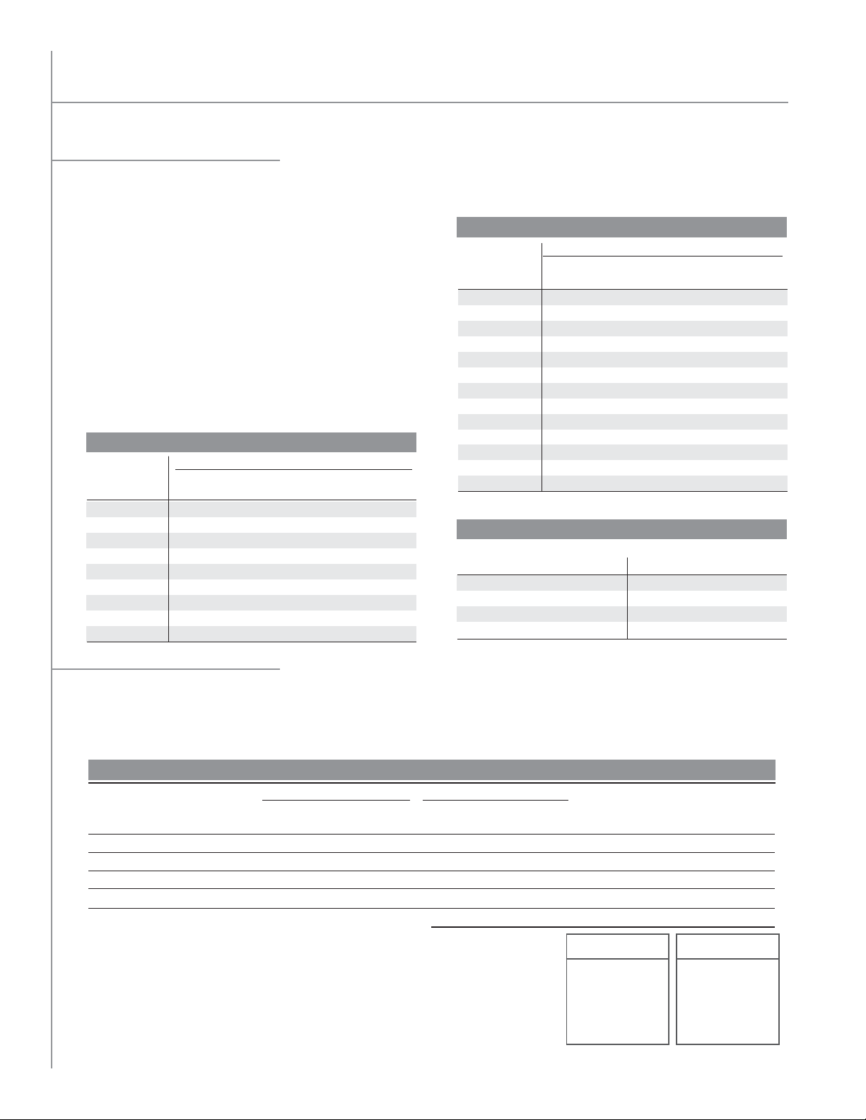
* Beyond the normal limits for single-stage compressor application.
* Beyond the normal limits for single-stage compressor application.
EVAPORATOR
TEMP (˚F)
-40
-30
-20
-10
0
5
10
15
20
25
30
40
50
90
1.66
1.57
1.49
1.42
1.36
1.33
1.31
1.28
1.26
1.24
1.22
1.18
1.14
100
1.73
1.62
1.53
1.46
1.40
1.37
1.34
1.32
1.29
1.27
1.25
1.21
1.17
110
1.80
1.68
1.58
1.50
1.44
1.41
1.38
1.35
1.33
1.31
1.28
1.24
1.20
120
2.00
1.80
1.65
1.57
1.50
1.46
1.43
1.40
1.37
1.35
1.32
1.27
1.23
130
*
*
*
1.64
1.56
1.52
1.49
1.46
1.43
1.40
1.37
1.31
1.26
140
*
*
*
*
1.62
1.59
1.55
1.52
1.49
1.45
1.42
1.35
1.29
CONDENSING TEMPERATURE (˚F)
HERMETIC COMPRESSOR
TABLE 1
* Beyond the normal limits for single-stage compressor application.
EVAPORATOR
TEMP (˚F)
-40
-30
-20
-10
0
5
10
15
20
25
30
40
50
90
1.66
1.57
1.49
1.42
1.36
1.33
1.31
1.28
1.26
1.24
1.22
1.18
1.14
100
1.73
1.62
1.53
1.46
1.40
1.37
1.34
1.32
1.29
1.27
1.25
1.21
1.17
110
1.80
1.68
1.58
1.50
1.44
1.41
1.38
1.35
1.33
1.31
1.28
1.24
1.20
120
2.00
1.80
1.65
1.57
1.50
1.46
1.43
1.40
1.37
1.35
1.32
1.27
1.23
130
*
*
*
1.64
1.56
1.52
1.49
1.46
1.43
1.40
1.37
1.31
1.26
140
*
*
*
*
1.62
1.59
1.55
1.52
1.49
1.45
1.42
1.35
1.29
CONDENSING TEMPERATURE (˚F)
HERMETIC COMPRESS
OR
EVAPORATOR
TEMP (˚F)
-30
-20
-10
0
10
20
30
40
50
90
1.37
1.33
1.28
1.24
1.21
1.17
1.14
1.12
1.09
100
1.42
1.37
1.32
1.28
1.24
1.20
1.17
1.15
1.12
110
1.47
1.42
1.37
1.32
1.28
1.24
1.20
1.17
1.14
120
*
1.47
1.42
1.37
1.32
1.28
1.24
1.20
1.17
130
*
*
1.47
1.41
1.36
1.32
1.27
1.23
1.20
140
*
*
*
1.47
1.42
1.37
1.32
1.28
1.24
CONDENSING TEMPERATURE (˚F)
OPEN COMPRESSOR
TABLE 1
TABLE 2
* Beyond the normal limits for single-stage compressor application.
* Beyond the normal limits for single-stage compressor application.
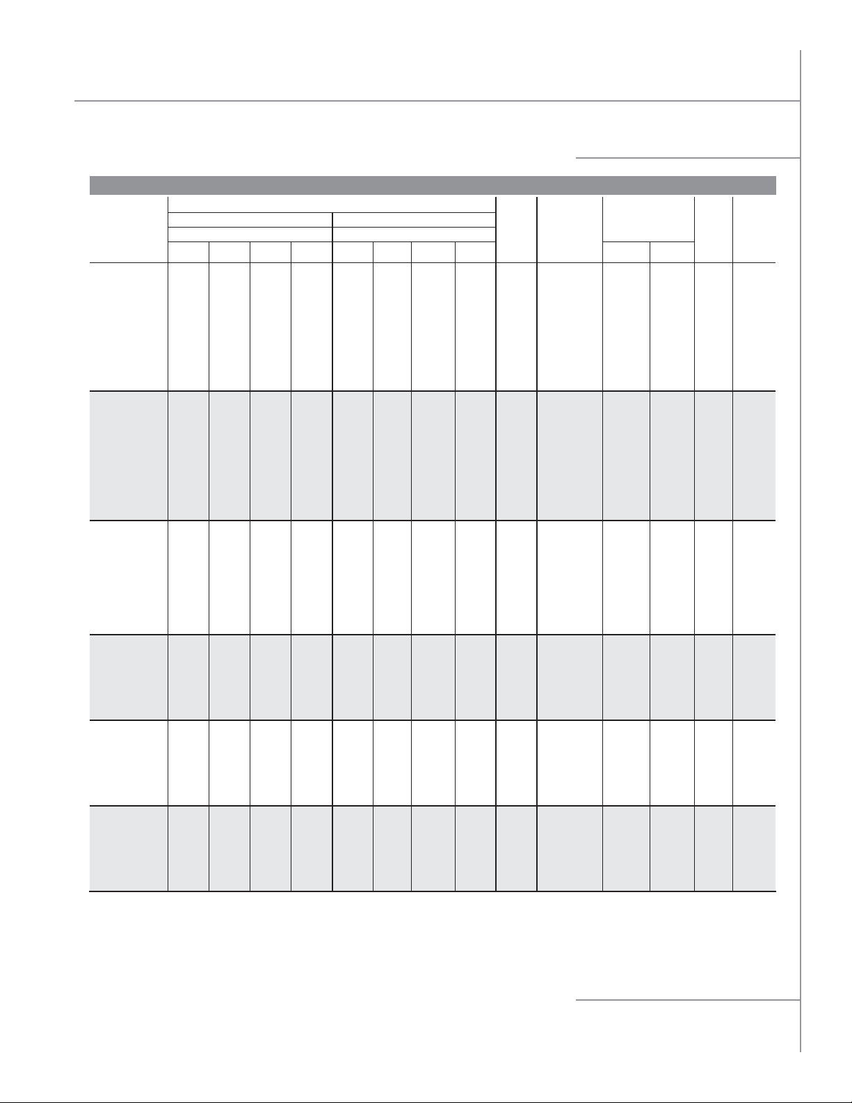
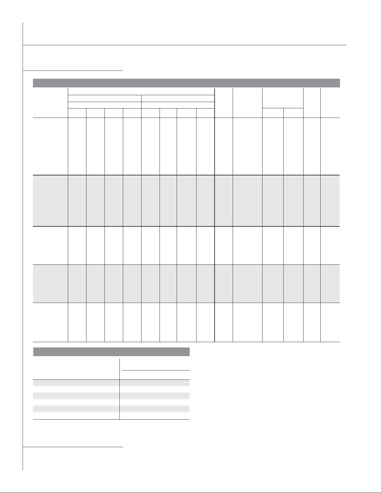
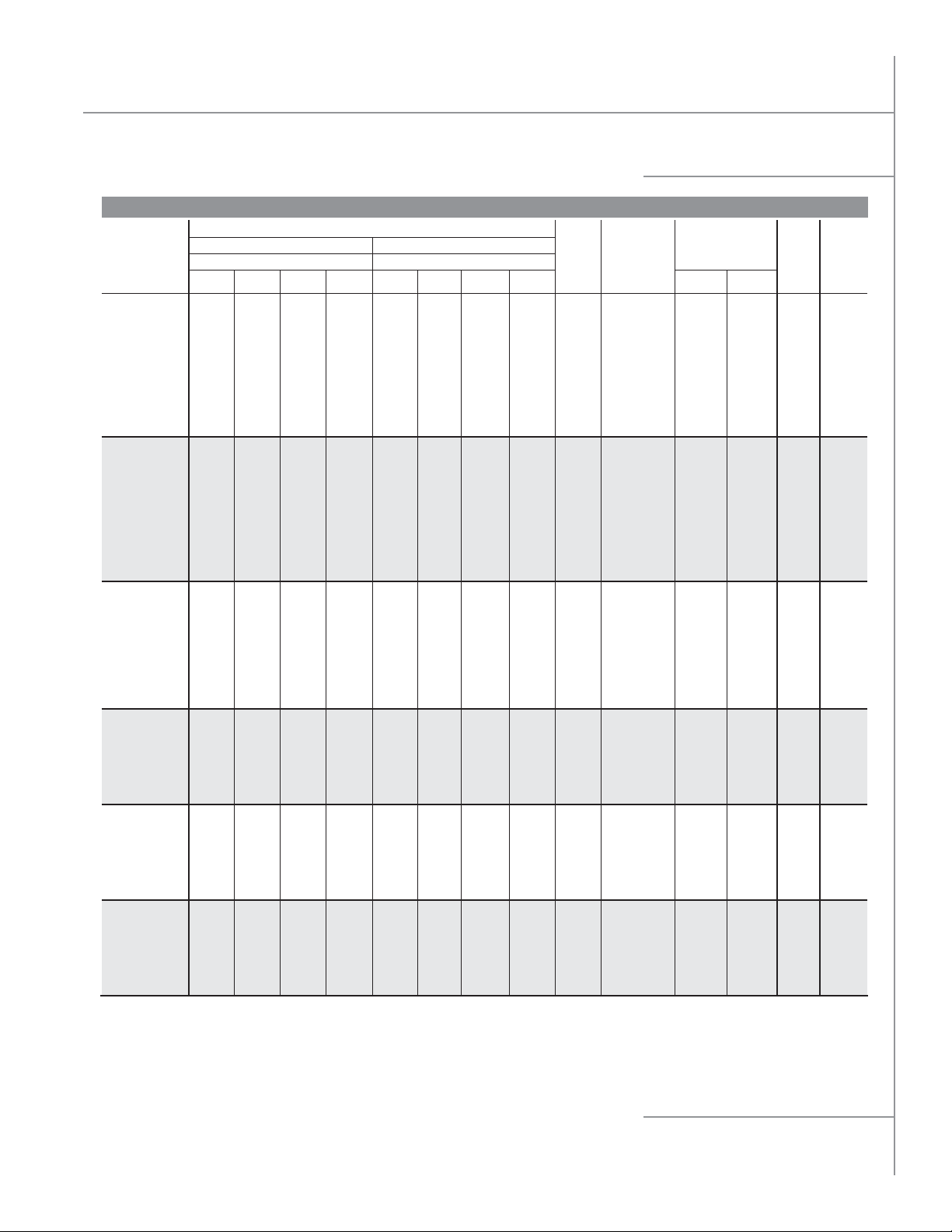
System Selection
THR Total Heat of Rejection
n Condenser total heat of rejection (BTU/h) is the sum of the evaporator refrigeration effect and the heat of compression
which varies with compressor type and operating conditions.
THR Calculation Method
n THR = Open Reciprocating Compressor Capacity
(BTU/h) + (2545 x BHP)
n THR = Suction Gas Cooled Hermetic Reciprocating
Compressor Capacity (BTU/h) + (3413 x kW)
THR Estimated Method
n THR may be estimated by multiplying the rated
compressor BTU/h capacity by the compressor
operating condition factor shown in Table 1 or 2.
Multiply result by altitude factor when applicable.
EVAPORATOR
TEMP (˚F)
* Beyond the normal limits for single-stage compressor application.
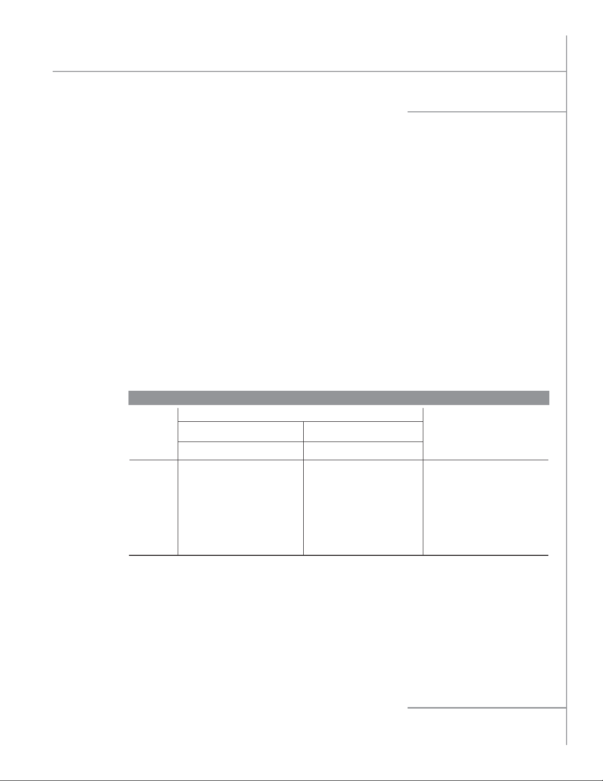
Multi-Circuit Selection
n Condenser coils may be divided into several individual refrigeration circuits or systems; each sized for a specific refrigerant,
THR capacity and TD. Systems are tagged for identification from left to right; facing the connection end. Avoid 3 row
condensers. Add excess circuits to low TD sections next to high TD sections. Add excess circuits to outboard sections.
Temperature fan cycling is recommended with multi-circuited condensers.
COMP
NOM
HP
6
9
10
12
Selection
n LAVA-14410 Rated at THR of 457.3 MBH with R-404A at 15°F TD.
LAVA-14410 Unit lists 34 Circuits.
n Sample Calculation: THR Req’d./Circuit = 426304 ÷ 34 = 12538.
LAVA-14410 = 457300 ÷ 34 = 13450 (Available THR/Circuit).
n Circuits Req’d. = Select THR ÷ THR/Circuit. Example: 56460 ÷ 13450 = 4.2 Circuits.
n Assign Number of Circuits System and System Number Left to Right.
Actual TD = (Circuits Req’d ÷ Assign Circuits) x Design TD.
Example: 4.2 ÷ 4 x 15 = 15.7.
-30
-20
-10
0
10
20
30
40
50
REF
134a
404A
404A
22
90
1.37
1.33
1.28
1.24
1.21
1.17
1.14
1.12
1.09
SAMPLE CALCULATION:
DESIGN
TD
°F
15
10
10
15
SAT
SUCT
°F
+20
-20
-20
+20
TABLE 2
CONDENSING TEMPERATURE (˚F)
100
1.42
1.37
1.32
1.28
1.24
1.20
1.17
1.15
1.12
SAT
COND
110
105
105
110
OPEN COMPRESSOR
110
1.47
1.42
1.37
1.32
1.28
1.24
1.20
1.17
1.14
NET
BTU/h
°F
40090
45900
50640
104000
120
*
1.47
1.42
1.37
1.32
1.28
1.24
1.20
1.17
95°F AMBIENT-SUCTION COOLED SEMI-HERMETIC RECIPROCATING COMPRESSORS
COMPRESS
MOTOR
kW
4.3
8.1
9.6
9.7
130
*
*
1.47
1.41
1.36
1.32
1.27
1.23
1.20
OR RATING
BTU
14676
27645
32765
33106
140
*
*
*
1.47
1.42
1.37
1.32
1.28
1.24
TOTAL
BTU/h
54,766
73,545
83,405
137,106
EVAPORATOR
TEMP (˚F)
-40
-30
-20
-10
0
5
10
15
20
25
30
40
50
* Beyond the normal limits for single-stage compressor application.
FEET
1,000
2,000
3,000
4,000
90
1.66
1.57
1.49
1.42
1.36
1.33
1.31
1.28
1.26
1.24
1.22
1.18
1.14
FACTOR
1.02
1.05
1.07
1.10
BASED ON R-404A AT 15°FTD
SELECT
REF
FACTOR
÷
0.97
÷
1.00
÷
1.00
÷
1.02
UNIT THR REQ’D
FACTOR
x
x
x
x
TD
1.0
1.5
1.5
1.0
=
=
=
=
THR
56460
110318
125108
134418
426304
R-404A - 1.00
R-22 - 1.02
R-134a - 0.97
TABLE 1
HERMETIC COMPRESSO
CONDENSING TEMPERATURE (˚F)
100
110
120
1.73
1.80
2.00
1.62
1.68
1.80
1.53
1.58
1.65
1.46
1.50
1.57
1.40
1.44
1.50
1.37
1.41
1.46
1.34
1.38
1.43
1.32
1.35
1.40
1.29
1.33
1.37
1.27
1.31
1.35
1.25
1.28
1.32
1.21
1.24
1.27
1.17
1.20
1.23
R
130
*
*
*
1.64
1.56
1.52
1.49
1.46
1.43
1.40
1.37
1.31
1.26
TABLE 3
ALTITUDE
CAP
PER
CIRCUIT
13450
13450
13450
13450
REF FACTOR
CIRCUIT
REQ’D
4.2
8.2
9.3
10.0
FEET
5,000
6,000
7,000
8,000
#
CIR
4
10
10
10
34
SYSTEM
NUMBER
L TO R
1
2
3
4
TD FACTOR
10°F - 1.50
15°F - 1.00
20°F - 0.75
25°F - 0.60
FACTOR
ACTUAL
1.12
1.15
1.17
1.24
15.7
15.0
140
*
*
*
*
1.62
1.59
1.55
1.52
1.49
1.45
1.42
1.35
1.29
TD
°F
8.2
9.3
Levitor II Air-Cooled Condenser
Levitor Application
Locate Condensers no closer than their width from
walls or other condensers. Avoid locations near
exhaust fans, plumbing vents, flues or chimneys.
Parallel Condensers should be the same models
resulting in the same refrigerant side pressure drops.
Compressor discharge lines should have equal
pressure drops to each condenser.
Summer Charge based on 25% of condenser volume
with 90˚F liquid. Multiply by 1.1 for R-407A.
Winter Charge based on 90% of condenser volume
with -20˚F liquid. Multiply by 1.08 for R-407A.
Receiver Capacity should be sized to store condenser
summer charge, plus the condenser low ambient
allowance, plus the evaporator charge, plus an
allowance for piping and heat reclaim coil charges.
REFRIGERANT LINE CAPACITY DATA
COPPER
LINE
SIZE
O.D.
5/8
7/8
1-1/8
1-3/8
1-5/8
2-1/8
2-5/8
COMPRESSOR DISCHARGE LINE
R-404A
R-407A
0.5
2.0
4.5
7.0
15.0
30.0
45.0
LINE CAPACITY IN TONS
R-134A
1.0
3.0
6.5
15.0
20.0
45.0
75.0
0.5
2.0
4.5
7.0
11.0
28.0
43.0
Compressor Discharge lines should be sized to
minimize pressure drops and maintain oil return gas
velocities. Each connection should be looped to the
top of the condenser.
Gravity Liquid Drain Lines should drop from each
outlet as low as possible before headering or running
horizontally. Pitch downhill to receiver.
Off-Line Coil Sections will have refrigerant pressures
corresponding to the ambient. Check valves or
isolating valves should be installed in the liquid line
drains to prevent refrigerant migration and receiver
pressure loss.
See Installation and Operating instructions for piping, holdback and fan cycling details.
LBS. OF REFRIGERANT
CONDENSER TO RECEIVER
LIQUID LINE 100'
R-404A
3.0
6.0
10.4
16.0
23.0
40.0
62.0
R-407A
3.6
7.4
12.7
19.2
29.0
47.0
73.0
R-134A
3.7
7.7
13.0
20.0
28.5
46.0
72.0
LIQUID PER 100'
R-404A
11.0
22.0
36.0
55.0
78.0
138.0
212.0
OF LENGTH
R-407A
13.0
25.0
42.0
64.0
90.0
160.0
245.0
R-134A
13.0
26.0
43.0
65.0
92.0
163.0
250.0
n Capacity is compressor suction tons for application between -40°F and +40°F suction at condensing
temperatures between 80°F and 120°F sat.
n For multiple or unloading compressor applications, the vertical discharge riser from the compressor
may need to be one size smaller.
n This table data is only to be used as a guide. For exact values, please calculate to your specific job line
lengths and design pressure/temp values using ASHRAE handbook or ARI refrigerant tables.
LEVITOR II AIR-COOLED CONDENSER
Specifications subject to change without notice.
3
Levitor II Air-Cooled Condenser
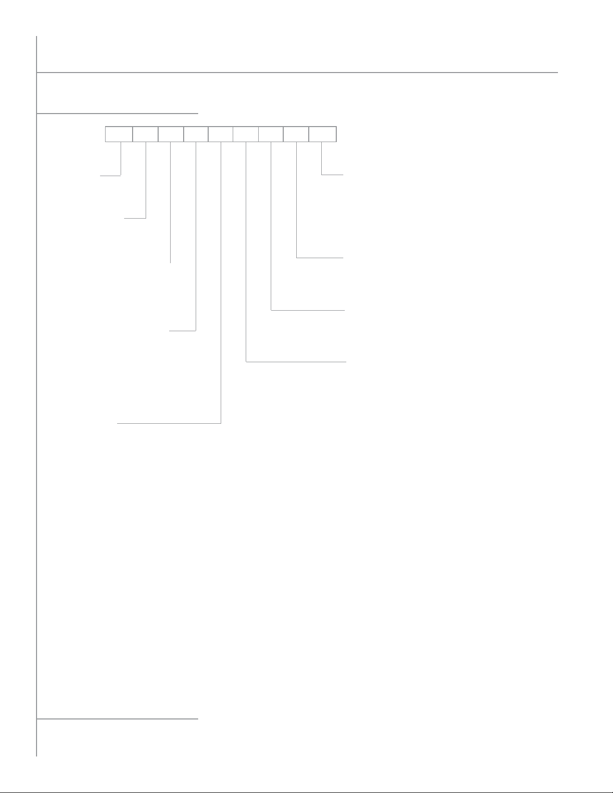
Model Key
LAVA12410 M
UNIT TYPE:
L=Levitor Condenser
TUBE DIAMETER:
A=3/8 O.D.
E=1/2 O.D.
FAN DISCHARGE DIRECTIONS:
H=Horizontal
V= Vertical
X=Hinged Vertical
E=Hinged Horizontal
FAN/MOTOR COMBINATION:
A=1 HP 850 RPM 30"
B=1/2 HP 1140 RPM 24"
C=1-1/2 HP 850 RPM 30"
E=1/2 HP 575 RPM 30"
F=1-1/2 HP 1140 RPM 30"
FANS WIDE: 1, 2
VOLTAGE:
A=230/1/60 (24” Fan B Model Only)
K=208-230/3/60
M=460/3/60
P=575/3/60
U=380/3/50 (Capacity Derate of Around 10%)
FIN SPACING:
08 =8 FPI
10 =10 FPI
12 =12 FPI
ROWS DEEP:
2
3
4
FANS IN LINE:
1
2
3
4
5
6
7=24" Fan Only (B Motor)
LEVITOR II AIR-COOLED CONDENSER
4
Specifications subject to change without notice.
Levitor II Air-Cooled Condenser
LAVE/LEVE Performance Data
LAVE Performance Data
ONE FAN WIDE
TOTAL HEAT OF REJECTION (MBH)
R-407AR-404A, R-507
TEMPERATURE DIFFERENCE TEMPERATURE DIFFERENCE
MODEL
LAVE11208 35.2 52.8 70.3 87.9 34.4 51.6 68.8 86.0 6480 Compliant 4 17 52 437
LAVE11210 41.3 61.9 82.5 103.1 40.5 60.7 81.0 101.2 6420 Compliant 4 17 52 439
LAVE11212 45.9 68.9 91.9 114.8 45.7 68.6 91.4 114.3 6360 No 4 17 52 444
LAVE11308 47.1 70.6 94.1 117.7 46.4 69.6 92.8 116.0 6300 Compliant 6 25 52 466
LAVE11310 53.0 79.4 105.9 132.4 53.0 79.5 106.0 132.5 6200 Compliant 6 25 52 469
LAVE11312 57.1 85.6 114.2 142.7 58.3 87.5 116.6 145.8 6100 No 6 25 52 478
LAVE11408 55.9 83.9 111.9 139.8 56.6 84.8 113.1 141.4 6105 Compliant 8 33 52 495
LAVE11410 61.1 91.7 122.2 152.8 63.5 95.3 127.1 158.8 5975 Compliant 8 33 52 499
LAVE11412 64.7 97.1 129.5 161.8 68.3 102.5 136.6 170.8 5835 No 8 33 52 508
LAVE12208 70.3 105.5 140.7 175.9 68.8 103.2 137.6 172.0 12960 Compliant 9 32 55 718
LAVE12210 82.5 123.8 165.0 206.3 81.0 121.5 162.0 202.5 12840 Compliant 9 32 55 721
LAVE12212 91.9 137.8 183.7 229.6 91.4 137.1 182.9 228.6 12720 No 9 32 55 729
LAVE12308 94.1 141.2 188.3 235.4 92.8 139.2 185.6 232.1 12600 Compliant 13 48 55 773
LAVE12310 105.9 158.9 211.8 264.8 106.0 159.0 212.1 265.1 12400 Compliant 13 48 55 779
LAVE12312 114.2 171.2 228.3 285.4 116.6 175.0 233.3 291.6 12200 No 13 48 55 792
LAVE12408 111.9 167.8 223.8 279.7 113.1 169.7 226.3 282.8 12210 Compliant 17 64 55 830
LAVE12410 122.2 183.3 244.5 305.6 127.1 190.6 254.1 317.6 11950 Compliant 17 64 55 838
LAVE12412 129.5 194.2 258.9 323.7 136.6 205.0 273.3 341.6 11670 No 17 64 55 855
LAVE13210 123.8 185.6 247.5 309.4 121.5 182.2 242.9 303.7 19260 Compliant 13 48 57 1041
LAVE13212 137.8 206.7 275.6 344.5 137.1 205.7 274.3 342.9 19080 No 13 48 57 1060
LAVE13308 141.2 211.8 282.4 353.0 139.2 208.8 278.5 348.1 18900 Compliant 18 72 57 1126
LAVE13310 158.9 238.3 317.8 397.2 159.0 238.6 318.1 397.6 18600 Compliant 18 72 57 1135
LAVE13312 171.2 256.9 342.5 428.1 175.0 262.4 349.9 437.4 18300 No 18 72 57 1153
LAVE13408 167.8 251.7 335.6 419.5 169.7 254.5 339.4 424.2 18315 Compliant 24 96 57 1210
LAVE13410 183.3 275.0 366.7 458.4 190.6 285.9 381.2 476.4 17925 Compliant 24 96 57 1223
LAVE13412 194.2 291.3 388.4 485.5 205.0 307.4 409.9 512.4 17505 No 24 96 57 1247
LAVE14308 188.3 282.4 376.6 470.7 185.6 278.5 371.3 464.1 25200 Compliant 24 96 58 1437
LAVE14310 211.8 317.8 423.7 529.6 212.1 318.1 424.1 530.1 24800 Compliant 24 96 58 1449
LAVE14312 228.3 342.5 456.6 570.8 233.3 349.9 466.6 583.2 24400 No 24 96 58 1474
LAVE14408 223.8 335.6 447.5 559.4 226.3 339.4 452.5 565.7 24420 Compliant 32 127 58 1550
LAVE14410 244.5 366.7 488.9 611.1 254.1 381.2 508.2 635.3 23900 Compliant 32 127 58 1566
LAVE14412 258.9 388.4 517.9 647.3 273.3 409.9 546.6 683.2 23340 No 32 127 58 1599
LAVE15308 235.4 353.0 470.7 588.4 232.1 348.1 464.1 580.1 31500 Compliant 32 119 59 2020
LAVE15310 264.8 397.2 529.6 662.0 265.1 397.6 530.1 662.7 31000 Compliant 32 119 59 2035
LAVE15312 285.4 428.1 570.8 713.5 291.6 437.4 583.2 729.0 30500 No 32 119 59 2066
LAVE15408 279.7 419.5 559.4 699.2 282.8 424.2 565.7 707.1 30525 Compliant 41 159 59 2160
LAVE15410 305.6 458.4 611.1 763.9 317.6 476.4 635.3 794.1 29875 Compliant 41 159 59 2181
LAVE15412 323.7 485.5 647.3 809.2 341.6 512.4 683.2 854.0 29175 No 41 159 59 2222
LEVE16308 282.4 423.6 564.9 706.1 278.5 417.7 556.9 696.2 37800 Compliant 65 266 60 2554
LEVE16310 317.8 476.7 635.5 794.4 318.1 477.1 636.2 795.2 37200 Compliant 65 266 60 2573
LEVE16312 342.5 513.7 684.9 856.2 349.9 524.9 699.9 874.8 36600 No 65 266 60 2610
LEVE16408 335.6 503.5 671.3 839.1 339.4 509.1 678.8 848.5 36630 Compliant 84 354 60 2784
LEVE16410 366.7 550.0 733.4 916.7 381.2 571.7 762.3 952.9 35850 Compliant 84 354 60 2808
LEVE16412 388.4 582.6 776.8 971.0 409.9 614.9 819.8 1024.8 35010 No 84 354 60 2858
10°F
15°F 20°F 25°F 10°F 15°F
20°F
25°F
The temperature difference is between the saturated condensing temp. and the entering air temp.to the condenser.
AIR
FLOW
(CFM)
CEC
TITLE 24
COMPLIANT
NOTE: Ratings are based on 85°F-115°F entering air temperature and 0˚F sub-cooling.
CONDE
CHARGE R-404A
SUMMER WINTER
NSER
(LBS)
EST
SOUND
10’
(dBA)
SHIP
WEIGHT
(LBS)
See Corrections Factor Table on page 6. See Electrical Motor AMP Data table on page 13.
LEVITOR II AIR-COOLED CONDENSER
Specifications subject to change without notice.
5
Levitor II Air-Cooled Condenser
LAVE/LEVE Performance Data
LAVE Performance Data
TWO FANS WIDE
TOTAL HEAT OF REJECTION (MBH)
R-407AR-404A, R-507
TEMPERATURE DIFFERENCE TEMPERATURE DIFFERENCE
MODEL
LAVE22208 140.7 211.0 281.4 351.7 137.6 206.4 275.2 344.0 25920 Compliant 18 64 58 1311
LAVE22210 165.0 247.5 330.0 412.5 162.0 242.9 323.9 404.9 25680 Compliant 18 64 58 1320
LAVE22212 183.7 275.6 367.4 459.3 182.9 274.3 365.7 457.2 25440 No 18 64 58 1336
LAVE22308 188.3 282.4 376.6 470.7 185.6 278.5 371.3 464.1 25200 Compliant 26 96 58 1425
LAVE22310 211.8 317.8 423.7 529.6 212.1 318.1 424.1 530.1 24800 Compliant 26 96 58 1437
LAVE22312 228.3 342.5 456.6 570.8 233.3 349.9 466.6 583.2 24400 No 26 96 58 1462
LAVE22408 223.8 335.6 447.5 559.4 226.3 339.4 452.5 565.7 24420 Compliant 34 128 58 1539
LAVE22410 244.5 366.7 488.9 611.1 254.1 381.2 508.2 635.3 23900 Compliant 34 128 58 1555
LAVE22412 258.9 388.4 517.9 647.3 273.3 409.9 546.6 683.2 23340 No 34 128 58 1588
LAVE23210 247.5 371.3 495.0 618.8 242.9 364.4 485.9 607.4 38520 Compliant 26 96 60 1875
LAVE23212 275.6 413.4 551.1 688.9 274.3 411.4 548.6 685.7 38160 No 26 96 60 1912
LAVE23308 282.4 423.6 564.9 706.1 278.5 417.7 556.9 696.2 37800 Compliant 36 144 60 2044
LAVE23310 317.8 476.7 635.5 794.4 318.1 477.1 636.2 795.2 37200 Compliant 36 144 60 2063
LAVE23312 342.5 513.7 684.9 856.2 349.9 524.9 699.9 874.8 36600 No 36 144 60 2100
LAVE23408 335.6 503.5 671.3 839.1 339.4 509.1 678.8 848.5 36630 Compliant 48 192 60 2214
LAVE23410 366.7 550.0 733.4 916.7 381.2 571.7 762.3 952.9 35850 Compliant 48 192 60 2238
LAVE23412 388.4 582.6 776.8 971.0 409.9 614.9 819.8 1024.8 35010 No 48 192 60 2287
LAVE24308 376.6 564.9 753.1 941.4 371.3 556.9 742.6 928.2 50400 Compliant 48 192 61 2526
LAVE24310 423.7 635.5 847.4 1059.2 424.1 636.2 848.2 1060.3 49600 Compliant 48 192 61 2651
LAVE24312 456.6 684.9 913.3 1141.6 466.6 699.9 933.1 1166.4 48800 No 48 192 61 2700
LAVE24408 447.5 671.3 895.0 1118.8 452.5 678.8 905.1 1131.3 48840 Compliant 64 254 61 2851
LAVE24410 488.9 733.4 977.8 1222.3 508.2 762.3 1016.4 1270.5 47800 Compliant 64 254 61 2884
LAVE24412 517.9 776.8 1035.7 1294.6 546.6 819.8 1093.1 1366.4 46680 No 64 254 61 2950
LAVE25308 470.7 706.1 941.4 1176.8 464.1 696.2 928.2 1160.3 63000 Compliant 64 238 62 3725
LAVE25310 529.6 794.4 1059.2 1324.1 530.1 795.2 1060.3 1325.4 62000 Compliant 64 238 62 3755
LAVE25312 570.8 856.2 1141.6 1427.0 583.2 874.8 1166.4 1458.0 61000 No 64 238 62 3817
LAVE25408 559.4 839.1 1118.8 1398.5 565.7 848.5 1131.3 1414.2 61050 Compliant 82 318 62 4005
LAVE25410 611.1 916.7 1222.3 1527.9 635.3 952.9 1270.5 1588.2 59750 Compliant 82 318 62 4046
LAVE25412 647.3 971.0 1294.6 1618.3 683.2 1024.8 1366.4 1708.0 58350 No 82 318 62 4129
LEVE26308 564.9 847.3 1129.7 1412.1 556.9 835.4 1113.9 1392.3 75600 Compliant 130 532 63 4759
LEVE26310 635.5 953.3 1271.1 1588.9 636.2 954.3 1272.3 1590.4 74400 Compliant 130 532 63 4796
LEVE26312 684.9 1027.4 1369.9 1712.4 699.9 1049.8 1399.7 1749.6 73200 No 130 532 63 4870
LEVE26408 671.3 1006.9 1342.5 1678.2 678.8 1018.2 1357.6 1697.0 73260 Compliant 168 708 63 5218
LEVE26410 733.4 1100.1 1466.7 1833.4 762.3 1143.5 1524.6 1905.8 71700 Compliant 168 708 63 5268
LEVE26412 776.8 1165.2 1553.6 1942.0 819.8 1229.8 1639.7 2049.6 70020 No 168 708 63 5366
10°F
15°F 20°F 25°F 10°F 15°F
20°F
25°F
AIR
FLOW
(CFM)
CEC
TITLE 24
COMPLIANT
CONDENSER
CHARGE R-404A
(LBS)
SUMMER WINTER
EST
SOUND
10’
(dBA)
SHIP
WEIGHT
(LBS)
CORRECTIONS FACTOR TABLE
MULTIPLY R-404A BY
REFRIGERANTS CAPACITY FACTOR SUMMER WINTER
R-404A 1.00 1.00 1.00
R-134A 0.97 1.17 1.11
R-410A 1.02 1.02 1.03
R-22 1.02 1.14 1.09
R-407A See R-407A Chart 1.10 1.08
R-407C 0.98 x R-407A 1.09 1.07
For units using 380/3/50, multiply capacity by 0.90.
LEVITOR II AIR-COOLED CONDENSER
6
Specifications subject to change without notice.
CHARGE CORRECTION FACTOR
NOTE: Ratings are based on 85°F-115°F entering air temperature and 0˚F sub-cooling.
The temperature difference is between the saturated condensing temp. and the entering air temp.
to the condenser.
See Electrical Motor AMP Data tables on page 13.
Levitor II Air-Cooled Condenser
LAVA R-404A Performance Data
LAVA Performance Data
ONE FAN WIDE
TOTAL HEAT OF REJECTION (MBH)
R-407AR-404A, R-507
TEMPERATURE DIFFERENCE TEMPERATURE DIFFERENCE
MODEL
LAVA11208 41.9 62.8 83.8 104.7 40.3 60.5 80.7 100.8 9260 No 4 17 63 437
LAVA11210 48.8 73.2 97.6 122.0 47.3 71.0 94.6 118.3 9151 No 4 17 63 439
LAVA11212 54.3 81.5 108.7 135.8 53.4 80.1 106.8 133.5 9040 No 4 17 63 444
LAVA11308 58.4 87.6 116.9 146.1 56.4 84.5 112.7 140.9 8933 No 6 25 63 466
LAVA11310 65.4 98.1 130.8 163.5 65.0 97.5 130.0 162.4 8760 Compliant 6 25 63 469
LAVA11312 71.9 107.9 143.9 179.8 72.3 108.5 144.6 180.8 8574 No 6 25 63 478
LAVA11408 69.6 104.5 139.3 174.1 68.8 103.1 137.5 171.9 8582 Compliant 8 33 63 495
LAVA11410 76.2 114.3 152.4 190.5 77.4 116.2 154.9 193.6 8314 Compliant 8 33 63 499
LAVA11412 81.2 121.7 162.3 202.9 83.8 125.8 167.7 209.6 8025 No 8 33 63 508
LAVA12208 83.8 125.6 167.5 209.4 80.7 121.0 161.3 201.7 18520 No 9 32 66 718
LAVA12210 97.6 146.4 195.1 243.9 94.6 141.9 189.2 236.5 18302 No 9 32 66 721
LAVA12212 108.7 163.0 217.3 271.7 106.8 160.2 213.7 267.1 18080 No 9 32 66 729
LAVA12308 116.9 175.3 233.7 292.2 112.7 169.1 225.5 281.8 17866 No 13 48 66 773
LAVA12310 130.8 196.2 261.6 327.0 130.0 194.9 259.9 324.9 17520 Compliant 13 48 66 779
LAVA12312 143.9 215.8 287.7 359.6 144.6 217.0 289.3 361.6 17148 No 13 48 66 792
LAVA12408 139.3 208.9 278.5 348.2 137.5 206.3 275.0 343.8 17164 Compliant 17 64 66 830
LAVA12410 152.4 228.7 304.9 381.1 154.9 232.3 309.8 387.2 16628 Compliant 17 64 66 838
LAVA12412 162.3 243.5 324.6 405.8 167.7 251.5 335.3 419.2 16050 No 17 64 66 855
LAVA13210 146.4 219.5 292.7 365.9 141.9 212.9 283.8 354.8 27453 No 13 48 68 1041
LAVA13212 163.0 244.5 326.0 407.5 160.2 240.4 320.5 400.6 27120 No 13 48 68 1060
LAVA13308 175.3 262.9 350.6 438.2 169.1 253.6 338.2 422.7 26799 No 18 72 68 1126
LAVA13310 196.2 294.3 392.4 490.5 194.9 292.4 389.9 487.3 26280 Compliant 18 72 68 1135
LAVA13312 215.8 323.7 431.6 539.4 217.0 325.5 433.9 542.4 25722 No 18 72 68 1153
LAVA13408 208.9 313.4 417.8 522.3 206.3 309.4 412.5 515.6 25746 Compliant 24 96 68 1210
LAVA13410 228.7 343.0 457.3 571.6 232.3 348.5 464.6 580.8 24942 Compliant 24 96 68 1223
LAVA13412 243.5 365.2 486.9 608.7 251.5 377.3 503.0 628.8 24075 No 24 96 68 1247
LAVA14308 233.7 350.6 467.4 584.3 225.5 338.2 450.9 563.7 35732 No 24 96 69 1437
LAVA14310 261.6 392.4 523.2 654.0 259.9 389.9 519.8 649.8 35040 Compliant 24 96 69 1449
LAVA14312 287.7 431.6 575.4 719.3 289.3 433.9 578.6 723.2 34296 No 24 96 69 1474
LAVA14408 278.5 417.8 557.1 696.3 275.0 412.5 550.0 687.5 34328 Compliant 32 127 69 1550
LAVA14410 304.9 457.3 609.7 762.2 309.8 464.6 619.5 774.4 33256 Compliant 32 127 69 1566
LAVA14412 324.6 486.9 649.2 811.6 335.3 503.0 670.7 838.4 32100 No 32 127 69 1599
LAVA15308 292.2 438.2 584.3 730.4 281.8 422.7 563.7 704.6 44665 No 32 119 70 2020
LAVA15310 327.0 490.5 654.0 817.5 324.9 487.3 649.8 812.2 43800 Compliant 32 119 70 2035
LAVA15312 359.6 539.4 719.3 899.1 361.6 542.4 723.2 904.1 42870 No 32 119 70 2066
LAVA15408 348.2 522.3 696.3 870.4 343.8 515.6 687.5 859.4 42910 Compliant 41 159 70 2160
LAVA15410 381.1 571.6 762.2 952.7 387.2 580.8 774.4 968.0 41570 Compliant 41 159 70 2181
LAVA15412 405.8 608.7 811.6 1014.5 419.2 628.8 838.4 1047.9 40125 No 41 159 70 2222
LEVA16308 350.6 525.9 701.2 876.5 338.2 507.3 676.4 845.5 53598 No 65 266 71 2554
LEVA16310 392.4 588.6 784.8 981.0 389.9 584.8 779.7 974.7 52560 Compliant 65 266 71 2573
LEVA16312 431.6 647.3 863.1 1078.9 433.9 650.9 867.9 1084.9 51444 No 65 266 71 2610
LEVA16408 417.8 626.7 835.6 1044.5 412.5 618.8 825.0 1031.3 51492 Compliant 84 354 71 2784
LEVA16410 457.3 686.0 914.6 1143.3 464.6 697.0 929.3 1161.6 49884 Compliant 84 354 71 2808
LEVA16412 486.9 730.4 973.9 1217.3 503.0 754.5 1006.0 1257.5 48150 No 84 354 71 2858
10°F
15°F 20°F 25°F 10°F 15°F
20°F
25°F
The temperature difference is between the saturated condensing temp. and the entering air temp.to the condenser.
AIR
FLOW
(CFM)
CEC
TITLE 24
COMPLIANT
NOTE: Ratings are based on 85°F-115°F entering air temperature and 0˚F sub-cooling.
CO
NDENSER
CHARGE R-404A
(LBS)
SUMMER WINTER
EST
SOUND
10’
(dBA)
SHIP
WEIGHT
(LBS)
See Corrections Factor Table on page 8. See Electrical Motor AMP Data table on page 13.
LEVITOR II AIR-COOLED CONDENSER
Specifications subject to change without notice.
7
 Loading...