


L
e
L
e
viitt
v
orr
o
S
S
errii
e
e
s IIII
e
s
Aiirr--
A
C
C
o
o
oll
o
O
O
n
IIn
e
d
e
p
p
stt
s
M
M
d
err
e
a
n
a
n
allll
a
a
n
a
n
C
o
C
o
attii
a
d
d
attii
a
u
u
n
n
n
n
o
o
all
a
d
d
g
g
n
n
e
e
n
n
s
s
err
e
s
s
Levitor Series II Air Cooled Condensers (PN E208035_B)

TABLE OF CONTENTS
1 RECEIPT OF EQUIPMENT ………………………………………………………………………………………………2
1.1 INSPECTION…………………………………………………………………………………………………………..……2
1.2 LOSS OF GAS HOLDING CHARGE……………………………………………………………………………………..2
2 MODELS AND DIMENSIONS…………………………………………………………………………………………….2
2.1 UNIT MODELS………………………………………………………………………………………………………………2
2.2 30” UNIT DIMENSIONS AND MOTOR AMPS……………………………………….………………………………….3
2.3 30” UNIT MOTOR AMPS…………………………………………………………………………………………………..4
2.4 30” UNIT WEIGHTS AND REFRIGERANT CHARGES………………………………………………………………..5
2.5 24” UNIT DIMENSIONS AND MOTOR AMPS…………………………………………………………………………..6
3 UNIT LOCATION………………………………………………………………………..………………………………..…7
4 RIGGING…………………………………………………………………………………………………………………..…8
5 UNIT ASSEMBLY………………………………………………………………………………………………………….11
5.1 LEG ASSEMBLY FOR 30” FAN UNITS………………………………………………………………………………...11
5.2 OPTIONAL GRAVITY DAMPERS FOR 30” FAN UNITS……………………………………………………………..11
5.3 HORIZONAL AIRFLOW BASE SUPPORT……………………………………………………………………………..12
5.4 LEG ASSEMBLY FOR 24” FAN UNITS………………………………………………………………………………...12
6 INSTALLATION AND PIPING…………………………………………………………………………………………...13
6.1 MOUNTING THE UNIT…………………………………………………………………………………………………...13
6.2 INTERCONNECTING PIPING FOR DOUBLE WIDE UNITS…………………………………… …………………...13
6.3 REFRIGERATION PIPING……………………………………………………………………………………………….13
6.4 HOLDBACK FLOODING CONTROL……………………………………………………………………………………16
7 ELECTRICAL……………………………………………………………………………………………………………...17
7.1 FIELD WIRING………………………………………………………………………………………………………..…..17
7.2 MOTORS WIRED TO TERMINAL BLOCKS………………………………………………………………………..…17
7.3 MOTORS WIRED TO STANDARD FAN CYCLING CONTROL PANEL………………………………………..….18
7.4 FAN CYCLE OPERATION……………………………………………………………………………………………....19
7.5 CONTROL SETTINGS……………………………………………………….………………………………………..…19
7.6 TEMPERATURE SENSOR……………………………………………………………………………………………...19
8 INSPECTION AND CLEANING…………………………………………………………………………………………22
9 REPLACEMENT PARTS LISTS……………………………………………………………………………………..…22
TABLES
Table 1 30” UNIT DIMENSIONS.................................................................................................................................. 3
Table 2 30” UNIT FULL LOAD MOTOR AMPS............................................................................................................ 4
Table 3 30” UNIT WEIGHTS AND REFRIGERANT CHARGES.................................................................................. 5
Table 4 24” UNIT DIMENSIONS, AMPS, AND WEIGHTS ..........................................................................................6
Table 5 24” REFRIGERANT LINE SIZING ................................................................................................................15
Table 6 CONTROL PANEL SETTINGS – PRESSURE SENSING............................................................................ 20
Table 7 CONTROL PANEL SETTINGS – TEMPERATURE SENSING..................................................................... 21
Table 8 TYPICAL REPLACEMENT PART NUMBERS.............................................................................................. 22
Table 9 MISCELLANIOUS REPLACEMENT PART NUMBERS................................................................................ 23
FIGURES
Figure 1 30” UNIT DRAWINGS ............................................................................................................................................ 3
Figure 2 24” UNIT DIMENSIONS ......................................................................................................................................... 6
Figure 3 LOCATION REQUIREMENTS ............................................................................................................................... 7
Figure 4 RIGGING FOR 30” FAN UNITS ............................................................................................................................. 8
Figure 5 RIGGING FOR 30” FAN UNITS WITH RECEIVERS ............................................................................................. 9
Figure 6 RIGGING FOR 24” FAN UNITS ........................................................................................................................... 10
Figure 7 STANDARD 22” & 42” LEG ASSEMBLY ............................................................................................................. 11
Figure 8 GRAVITY DAMPER ASSEMBLY......................................................................................................................... 11
Figure 9 42” LEG & BRACING ASSEMBLY FOR 24"FAN UNITS ..................................................................................... 12
Figure 10 UNIT MOUNTING AND PIPING......................................................................................................................... 14
Figure 11 DOUBLE RISER DISCHARGE ARRANGEMENT ............................................................................................. 16
Figure 12 HOLDBACK FLOODING CONTROL ARRANGEMENTS .................................................................................. 16
Figure 13 TERMINAL BLOCK ONLY WIRING DIAGRAMS ( NC – C444 )........................................................................ 17
Figure 14 INDIVIDUAL FAN MOTOR CYCLING WIRING DIAGRAM ( -311 ) ................................................................... 18
Figure 15 FAN MOTOR CYCLING IN PAIRS WIRING DIAGRAM ( -331 )........................................................................ 18
Levitor Series II Air Cooled Condensers (PN E208035_B)
1
1 RECEIPT OF EQUIPMENT
1.1 INSPECTION
All equipment should be carefully checked for damage or shortages as soon as it is received. Each
shipment should be carefully checked against the bill of lading. If any damage or shortage is evident, a
notation must be made on the delivery receipt before it is signed and a claim should then be filed
against the freight carrier. Inspection and claims are the responsibility of the recipient.
1.2 LOSS OF GAS HOLDING CHARGE
The refrigeration coil section of each Levitor Series II unit is leak tested, evacuated to remove moisture
and then shipped with a pressurized nitrogen gas holding charge. Absence of this charge may indicate
a leak has developed in transit. The system should not be charged with refrigerant until it is verified
that there is no leak, or the source of the leak is located and repaired if necessary.
2 MODELS AND DIMENSIONS
2.1 UNIT MODELS
Units are available with 24” and 30” diameter fans and a variety of motor speeds and horsepower’s. All
units are designed for vertical air discharge, with horizontal air discharge as an option. Each unit is
constructed for the refrigerant and internal working pressure that is indicated on the unit nameplate. All
units contain the UL, cUL, and CSA labels to indicate the unit was manufactured using acceptable
practices by the governing bodies.
MODEL KEY: L A V A – 2 4 4 10 M
Levitor Voltage In
A – 208-230/1/60 (LAVB only)
Tube Diameter
A – 3/8”
E – 1/2" P – 575/3/60
U – 380/3/50
Air Discharge
V – Vertical
H – Horizontal
X – Hinged Vertical Airflow 08, 10 or 12
E – Hinged Horizontal Airflow
No. Rows Deep
Fan/Motor Combination
A – 30” Fan, 1 HP, 850 RPM
B – 24” Fan, 0.5 HP, 1140 RPM
C – 30” Fan, 1.5 HP, 850 RPM 1 to 7 for 24” fan units
E – 30” Fan, 0.5 HP, 575 RPM 1 to 6 for 30” fan units
F – 30” Fan, 1.5 HP, 1140 RPM
1 for single-wide units (inline)
2 for double-wide units (side-by-side)
K – 208-230/3/60
2, 3, or 4
M – 460/3/60
W – 415/3/50
Fins Per Inch
No. Fans Long
No. Fans Wide
Levitor Series II Air Cooled Condensers (PN E208035_B)
2
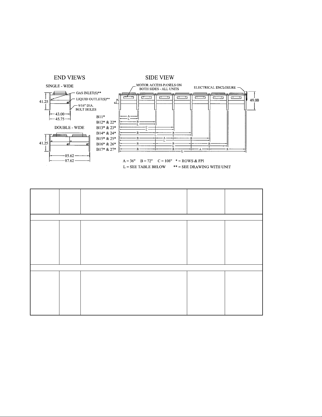
2.2 30” UNIT DIMENSIONS AND MOTOR AMPS
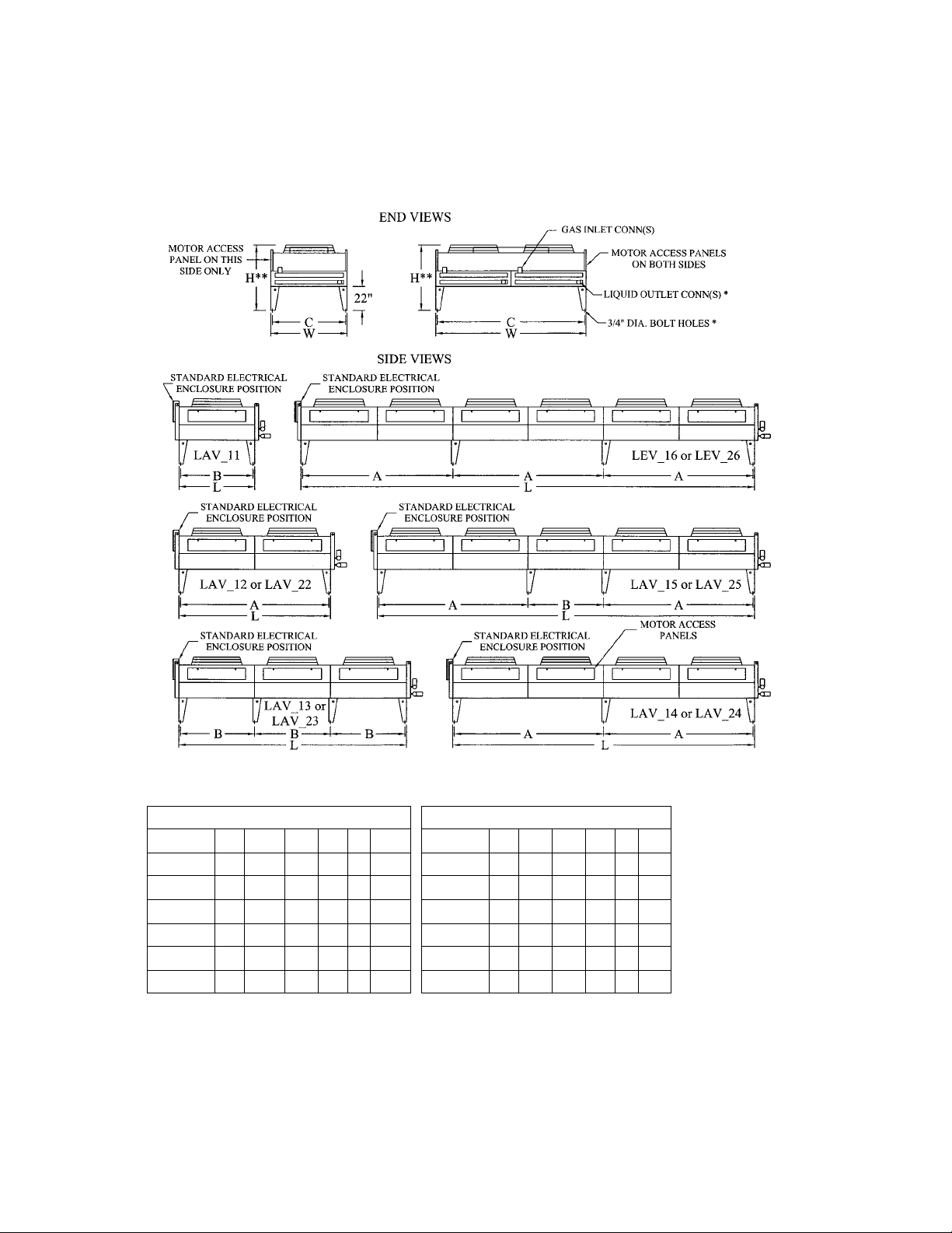
Figure 1 and Table 1 contain the overall dimensions, bolt hole locations, and motor amp draws for all of
the 30” diameter fan units.
FIGURE 1 30” UNIT DRAWINGS
TABLE 1 30” UNIT DIMENSIONS
DIMENSIONS (inches) DIMENSIONS (inches)
MODEL L W H** A B C MODEL L W H** A B C
LAV_11*** 58 45.25 54 - 54 41.25 - - - - - - LAV_12*** 112 45.25 54 108 - 41.25 LAV_22*** 112 90.5 54 108 - 86.5
LAV_13*** 166 45.25 54 108 54 41.25 LAV_23*** 166 90.5 54 108 54 86.5
LAV_14*** 220 45.25 54 108 - 41.25 LAV_24*** 220 90.5 54 108 - 86.5
LAV_15*** 274 45.25 58.5 108 54 41.25 LAV_25*** 274 90.5 58.5 108 54 86.5
LEV_16*** 328 45.25 58.5 108 - 41.25 LEV_26*** 328 90.5 58.5 108 - 86.5
* -
Connection size is determined by computerized circuiting program. See drawing with unit.
** - Includes standard 22” legs. Increase height accordingly if 30”, 36”, 42”, 48”, or 60” extended legs
are used. If the 48” or 60” extended legs are used, every fan section down the length of the unit has a
leg and gusset. 60” legs also have cross bracing. Legs, gussets, and bracing require field installation.
See unit drawing for details.
*** - Rows & FPI
Levitor Series II Air Cooled Condensers (PN E208035_B)
3
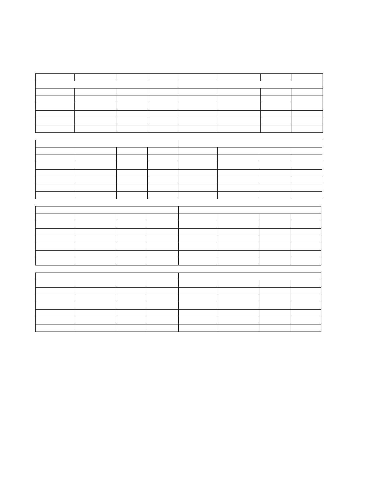
2.3 30” UNIT MOTOR AMPS
The following table contains the motor amps for the available fan motors.
TABLE 2 30” UNIT FULL LOAD MOTOR AMPS
MODEL 208/230/3/60 460/3/60 575/3/60 MODEL 208/230/3/60 460/3/60 575/3/60
ONE FAN WIDE 1 HP 850 RPM TWO FANS WIDE 1 HP 850 RPM
LAVA11*** 4.4 2.0 1.5 - - - LAVA12*** 8.8 4.0 3.0 LAVA22*** 17.6 8.0 6.0
LAVA13*** 13.2 6.0 4.5 LAVA23*** 26.4 12.0 9.0
LAVA14*** 17.6 8.0 6.0 LAVA24*** 35.2 16.0 12.0
LAVA15*** 22.0 10.0 7.5 LAVA25*** 44.0 20.0 15.0
LEVA16*** 26.4 12.0 9.0 LEVA26*** 52.8 24.0 18.0
ONE FAN WIDE 1.5 HP 850 RPM TWO FANS WIDE 1.5 HP 850 RPM
MODEL 208/230/3/60 460/3/60 575/3/60 MODEL 208/230/3/60 460/3/60 575/3/60
LAVC11*** 6.0 3.0 2.5 - - - LAVC12*** 12.0 6.0 5.0 LAVC22*** 24.0 12.0 10.0
LAVC13*** 18.0 9.0 7.5 LAVC23*** 36.0 18.0 15.0
LAVC14*** 24.0 12.0 10.0 LAVC24*** 48.0 24.0 20.0
LAVC15*** 30.0 15.0 12.5 LAVC25*** 60.0 30.0 25.0
LEVC16*** 36.0 18.0 15.0 LEVC26*** 72.0 36.0 30.0
ONE FAN WIDE 1/2 HP 575 RPM TWO FANS WIDE 1/2 HP 575 RPM
MODEL 208/230/3/60 460/3/60 575/3/60 MODEL 208/230/3/60 460/3/60 575/3/60
LAVE11*** 3.4 1.7 1.2 - - - LAVE12*** 6.8 3.4 2.4 LAVE22*** 13.6 6.8 4.8
LAVE13*** 10.2 5.1 3.6 LAVE23*** 20.4 10.2 7.2
LAVE14*** 13.6 6.8 4.8 LAVE24*** 27.2 13.6 9.6
LAVE15*** 17.0 8.5 6.0 LAVE25*** 34.0 17.0 12.0
LEVE16*** 20.4 10.2 7.2 LEVE26*** 40.8 20.4 14.4
ONE FAN WIDE 1.5 HP 1140 RPM TWO FANS WIDE 1.5 HP 1140 RPM
MODEL 208/230/3/60 460/3/60 575/3/60 MODEL 208/230/3/60 460/3/60 575/3/60
LAVF11*** 7.0 3.5 2.4 - - - LAVF12*** 14.0 7.0 4.8 LAVF22*** 28.0 14.0 9.6
LAVF13*** 21.0 10.5 7.2 LAVF23*** 42.0 21.0 14.4
LAVF14*** 28.0 14.0 9.6 LAVF24*** 56.0 28.0 19.2
LAVF15*** 35.0 17.5 12.0 LAVF25*** 70.0 35.0 24.0
LEVF16*** 42.0 21.0 14.4 LEVF26*** 84.0 42.0 28.8
*** - Model number shown does not include rows or fins per inch.
For unit Minimum unit Circuit Amps (MCA) and Maximum unit Overload Protection (MOP)
consult the factory wiring diagram supplied with the unit.
Levitor Series II Air Cooled Condensers (PN E208035_B)
4
2.4 30” UNIT WEIGHTS AND REFRIGERANT CHARGES
The following table contain approximate unit shipping weights and refrigerant charges for the 30” fan
units. The Summer Charge is based on 25% of condenser volume with 86°F liquid. The Winter Charge
is based on 90% of condenser volume with –20°F liquid.
TABLE 3 30” UNIT WEIGHTS AND REFRIGERANT CHARGES
CONDENSER CHARGE (LBS)
APPROX. R - 22 R – 404A
UNIT WT. (LBS) SUMMER WINTER SUMMER WINTER
ONE FAN WIDE UNITS
LAV_112** 445 4.3 20.2 3.8 18.4
LAV_113** 480 6.5 30.4 5.7 27.6
LAV_114** 510 8.6 40.5 7.5 36.8
LAV_122** 730 8.3 39.1 7.3 35.5
LAV_123** 790 12.4 58.6 10.9 53.3
LAV_124** 860 16.6 78.2 14.6 71.1
LAV_132** 1060 12.3 58.0 10.8 52.7
LAV_133** 1150 18.5 86.9 16.2 79.0
LAV_134** 1250 24.6 115.9 21.6 105.4
LAV_143** 1475 24.5 115.2 21.5 104.7
LAV_144** 1600 32.6 153.8 28.6 139.8
LAV_153** 2070 30.4 143.4 26.7 130.4
LAV_154** 2220 40.6 191.3 35.6 173.9
LEV_163** 2610 68.1 320.7 59.7 291.5
LEV_164** 2860 90.7 427.6 79.6 388.7
TWO FAN WIDE UNITS
LAV_222** 1340 16.6 78.2 14.6 71.1
LAV_223** 1460 24.6 117.3 21.6 106.6
LAV_224** 1590 33.2 156.4 29.1 142.2
LAV_232** 1910 24.6 115.9 21.6 105.4
LAV_233** 2100 36.9 173.8 32.4 158.0
LAV_234** 2290 49.2 231.8 43.2 210.7
LAV_243** 2700 48.9 230.3 42.9 209.4
LAV_244** 2950 65.2 307.2 57.2 279.3
LAV_253** 3820 61.0 308.9 53.5 280.8
LAV_254** 4130 81.3 382.6 71.3 347.8
LEV_263** 4870 136.2 641.3 119.5 583.0
LEV_264** 5370 181.6 855.0 159.3 777.3
** - Fins per inch
_ - Motors A, C, E, or F
Levitor Series II Air Cooled Condensers (PN E208035_B)
5
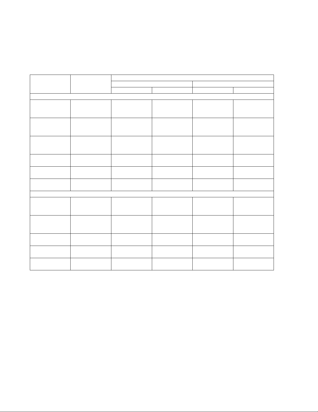
2.5 24” UNIT DIMENSIONS AND MOTOR AMPS
(2)
Figure 2 and Table 4 contain the overall dimensions, leg bolt hole locations, motor full load amps, and
weights for all of the units with 24” diameter fans.
Figure 2 24” UNIT DIMENSIONS
TABLE 4 24” UNIT DIMENSIONS, AMPS, AND WEIGHTS
TOTAL MOTOR FULL LOAD AMPS (1) FLOOD INCL.
DIM. CHARGE FLOOD
UNIT L 208/230/1 208-3 230-3 460-3 575 -3 (LBS)(R-22) CHRG. (LBS)
ONE FAN WIDE UNITS
LAVB11* 39 4.2 2.8 2.6 1.3 0.76 19 180
LAVB12* 75 8.4 5.6 5.2 2.6 1.52 39 360
LAVB13* 111 12.6 8.4 7.8 3.9 2.28 58 540
LAVB14* 147 16.8 11.2 10.4 5.2 3.04 86 720
LAVB15* 183 21.0 14.0 13.0 6.5 3.80 97 900
LAVB16* 219 25.2 16.8 15.6 7.8 4.56 116 1080
LAVB17* 262 29.4 19.6 18.2 9.1 5.32 144 1260
TWO FAN WIDE UNITS
- - - - - - - - LAVB22* 75 16.8 11.2 10.4 5.2 3.04 86 700
LAVB23* 111 25.2 16.8 15.6 7.8 4.56 116 1050
LAVB24* 147 33.6 22.4 20.8 10.4 6.08 172 1400
LAVB25* 183 42.0 28.0 26.0 13.0 7.60 194 1750
LAVB26* 219 50.4 33.6 31.2 15.6 9.12 232 2100
LAVB27* 262 58.8 39.2 36.4 18.2 10.64 288 2450
* - Model number shown does not include rows or fins per inch.
(1) For unit Minimum unit Circuit Amps (MCA) and Maximum unit Overload Protection (MOP)
consult the factory wiring diagram supplied with the unit.
(2) Values listed are for 4 Row units. For 3 Row units multiply by 0.75. For 2 Row units multiply
by 0.5.
WINTER WEIGHT
Levitor Series II Air Cooled Condensers (PN E208035_B)
6
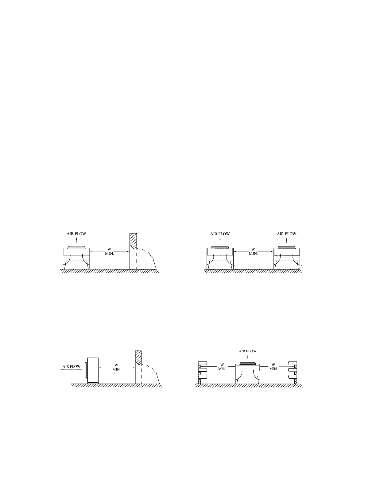
3 UNIT LOCATION
The Levitor Series II units require adequate space to allow unrestricted ambient airflow in to and out of
the fan section. Figure 3 gives general rules of the location of an air-cooled condenser in different
situations. The distances shown in the sketches should be increased whenever possible. The unit
position relative to the prevailing winds should be taken into account. Note that higher than expected
head pressures will result in poor system operation if the following suggested distances are not used.
So that the unit performs as predicted it should be located away from heated air exhausts, steam vents,
or corrosive airflow, whether it comes from the job site, or from another nearby source. A corrosive
atmosphere will require an appropriate coil coating, or copper fins to protect the coil and extend the life
of the unit.
Unit location with regard to noise should also be considered. An air-cooled condensing unit should be
located away from noise and vibration sensitive spaces to avoid transmission into workspaces.
Figure 3 LOCATION REQUIREMENTS
Walls or Barriers Multiple Units
For proper airflow and access, all sides of the
unit should be a minimum of “W” away from
any wall or barrier. Enough space should be
allowed for all maintenance work. Overhead
obstructions are not allowed.
For units placed side by side, the minimum
distance between units is the width of the
largest unit. If units are placed end to end, the
minimum distance between units is one fan
section long.
Walls or Barriers for Horizontal Airflow Decorative Fences
Units with horizontal airflow should be a
minimum of “W” away from any wall or barrier,
plus the air discharge should be free flowing
away from the unit.
Fences must have 50% free area, with 1 foot
undercut, a “W” minimum clearance, and must
not exceed the top of the unit.
W = Total width of the air-cooled condensing unit.
Levitor Series II Air Cooled Condensers (PN E208035_B)
7
 Loading...