

Krack KR14G-037 Installation Manual

G
G
a
a
s
s
D
D
K
K
effrr
e
R
R
o
o
S
S
stt
s
errii
e
U
niitt
U
n
e
e
s
s
C
C
o
o
oll
o
err
e
s
s
O
p
p
err
e
O
a
n
IIn
stt
M
s
M
allll
a
a
a
a
attii
a
n
d
n
attii
a
n
u
n
d
u
n
g
n
o
o
all
a
g
n
n
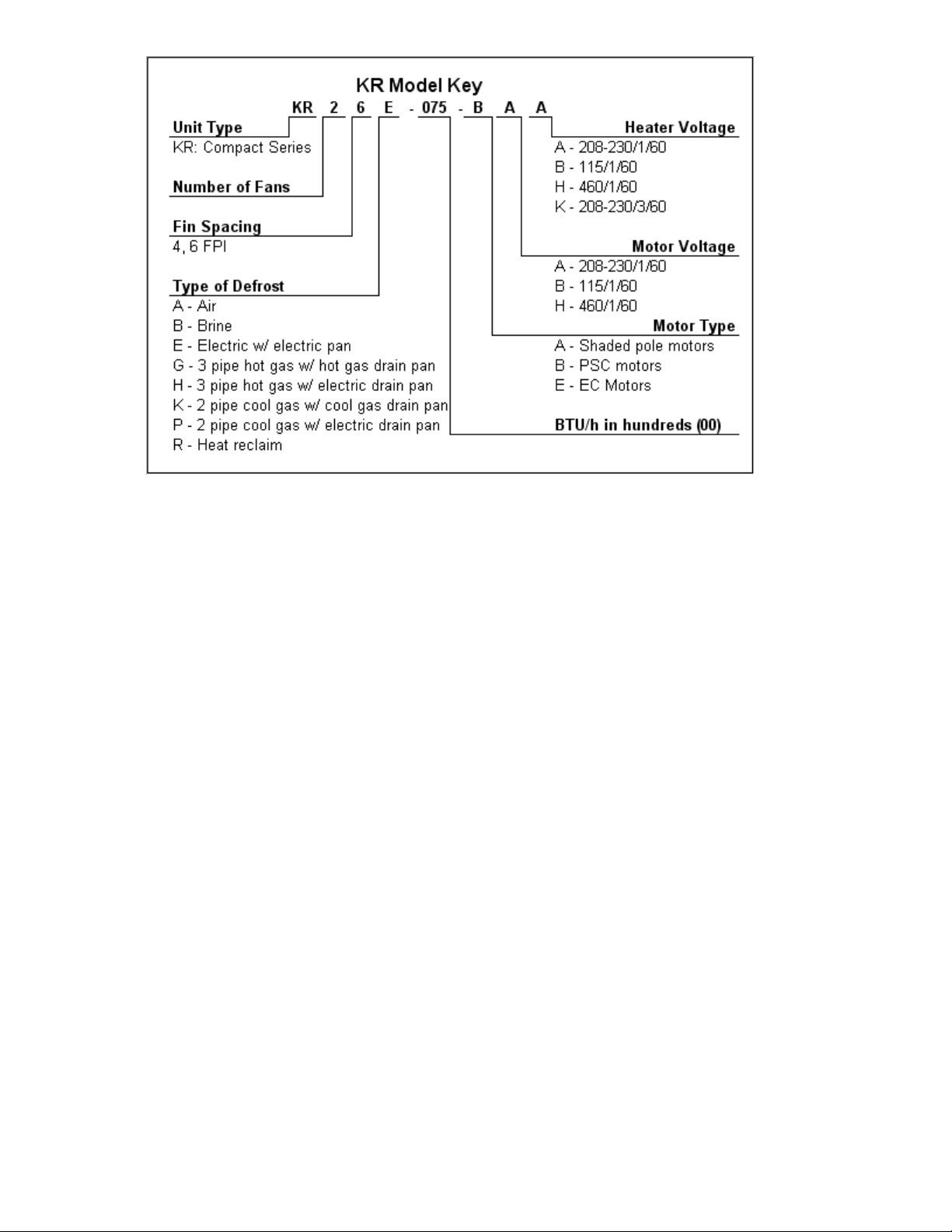
Gas Defrost Unit Coolers (E108319_D)

TABLE OF CONTENTS
1 LOCATION RECOMINDATIONS………………………………………………………………….2
2 UNIT MOUNTING…………………………………………………………………………………….2
3 DRAIN LINE………………………………………………………………………………………….3
4 REFRIGERATION PIPING………………………………………………………………………... 4
5 REFRIGERANT DISTRIBUTOR…………………………………………………………………...4
6 EXPANSION VALVE………………………………………………………………………………..6
7 WIRING……………………………………………………………………………………………….7
8 SEQUENCE OF OPERARIONS.………………………………………………………………….8
9 PRE-STARTUP………..………………………………………………………………………….…9
10 REPLACEMENT PARTS…………………………………………………………………………..9
CHARTS
TABLE 1 UNIT DIMENSIONS……………………………………………………………………….…3
TABLE 2 DISTRIBUTOR NOZZLES…………………………………………………………………. 5
TABLE 3 EXPANSIONS VALVES……………………………………………………………………..6
TABLE 4 FAN & HEATERS AMPERS………………………………………………………………...7
FIGURES
Figure 1 Unit Dimensions .............................................................................................................................. 3
Figure 2 H(HGE) – 3 Pipe Hot Gas Defrost with Electric Pan Heat ................................................. 9
Figure 3 G(HGG) – 3 Pipe Hot Gas Defrost with Hot Gas Pan Heat .............................................. 9
Figure 4 P(KGE) – 2Pipe Kool Gas Defrost with Electric Pan Heat ............................................. 10
Figure 5 K(KGG) – 2 Pipe Kool Gas Defrost with Gas Pan Defrost .............................................. 10
Figure 6 Wiring H(HGE)– 3 Pipe Hot Gas defrost with Electric Pan Heat ................................... 11
Figure 7 Wiring G(HGG) – 3 Pipe Hot Gas Defrost with Hot Gas Pan Heat ............................... 11
Figure 8 Wiring P(KGE) – 2 Pipe Kool Gas Defrost with Electric Pan Heat ................................ 12
Figure 9 Wiring K(KGG) – 2 Pipe Kool Gas Defrost with Gas Pan Defrost ............................................ 12
Gas Defrost Unit Coolers (E108319_D) 1
1 LOCATION RECOMMENDATIONS
Hot gas defrost unit coolers must have proper airflow to maintain a uniform room
temperature and have a complete defrost.
These units are draw thru design thus drawing air thru the cooling coil and discharging it
into the room via the unit fans. For best performance it is desirable to arrange the air
discharge toward the door of the cooler to minimize the entrance of warm moist air when
the door is open. The unit must be at least 12 inches from the wall to assure proper air
intake.
2 UNIT MOUNTING
The unit cooler may be suspended with 3/8" diameter hanger rods or flush mounted to
the ceiling using 5/16 minimum lag screws with flat washers. Rods should be double
nutted top and bottom.
The unit must be level in all directions to insure proper drainage of condensate.
Suspended units must have sufficient clearance above for cleaning the top.
Gas Defrost Unit Coolers (E108319_D) 2
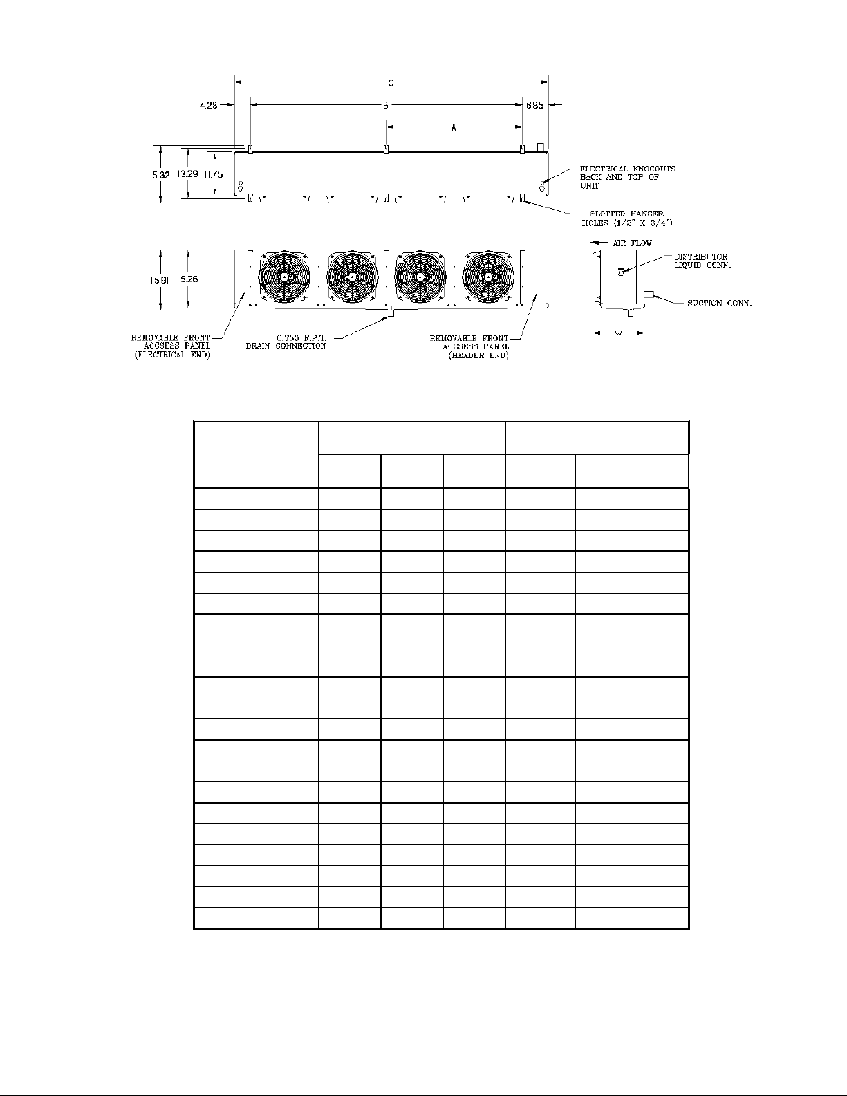
Figure 1 Unit Dimensions
MODEL
NUMBERS
DIMENSIONS (INCHES)
CONNECTIONS ODS (IN)
A B C
LIQUID
SUCTION
KR14*-037
-
18
29-1/8
1/2
5/8
KR24*-065
-
36
47-1/8
1/2
7/8
KR24*-074
-
36
47-1/8
1/2
7/8
KR34*-111
-
54
65-1/8
1/2
7/8
KR44*-148
36
72
83-1/8
1/2
1-1/8
KR54*-185
36
90
101-1/8
1/2
1-1/8
KR64*-213
54
108
119-1/8
1/2
1-1/8
KR64*-220
54
108
119-1/8
1/2
1-1/8
KR16*-035
-
18
29-1/8
1/2
5/8
KR16*-041
-
18
29-1/8
1/2
5/8
KR16*-045
-
18
29-1/8
1/2
5/8
KR26*-067
-
36
47-1/8
1/2
7/8
KR26*-075
-
36
47-1/8
1/2
7/8
KR26*-090
-
36
47-1/8
1/2
7/8
KR36*-126
-
54
65-1/8
1/2
7/8
KR36*-135
-
54
65-1/8
1/2
7/8
KR46*-160
36
72
83-1/8
1/2
1-1/8
KR46*-180
36
72
83-1/8
1/2
1-1/8
KR56*-192
36
90
101-1/8
1/2
1-1/8
KR66*-240
54
108
119-1/8
1/2
1-1/8
KR66*-270
54
108
119-1/8
1/2
1-1/8
Table 1 Unit Dimensions and Connection Sizes
Table1 lists mounting dimensions and sizes of suction, liquid and drain connections.
* May be G, H, K or P depending on type of defrost and type of
drain pan heat.
Gas Defrost Unit Coolers (E108319_D) 3

3 DRAIN LINE
The drain line should be as short and as steeply pitched as possible with a minimum of
1/4" drop per running foot. Any traps in the drain line must be located in an ambient
above freezing. If the temperature surrounding the trap or drain line is below freezing it
must be wrapped with a drain line heater. Be sure to also wrap the unit drain coupling.
Cover the drain line, drain coupling and heat tape with insulation. Be sure to follow the
manufacturer's recommendation when installing the drain line heat tape.
A union is recommended for ease of installation and future servicing. The union should
be located as close to the drain pan as possible. Use two wrenches when tightening to
prevent the drain fitting from twisting and damaging the unit.
Support long runs of drain line (i.e. more than a few feet) by hangers to avoid damage to
the drain pan.
4 REFRIGERATION PIPING
System design must conform to all codes, laws and regulations applying to the site of
installation. In addition the safety code for mechanical refrigeration.
Refrigerant line sizes and piping techniques should be obtained from the ASHRAE
Guide or equivalent reference. Under no circumstances should the refrigerant
connection size of the unit be used as the basis for sizing the lines.
The horizontal suction line should slope away from the unit toward the compressor.
Vertical suction risers may require a trap at the bottom of the riser for proper oil return.
There are two typical methods of defrosting a unit with hot gas. Figures 1 and 2 show
typical piping arrangements for 3 pipe hot gas defrost. Figures 3 and 4 show typical
piping arrangements for reverse cycle defrost.
For Food Service installations – seal any joint between unit cooler and cooler wall with a
sealant Listed by the National Sanitation Foundation.
5 REFRIGERANT DISTRIBUTOR
Distributor nozzles are included using a refrigerant distributor with a changeable nozzle
design. The nozzle(s) are packed in individual plastic envelopes along with a retainer
ring and instruction card. The instruction card tells what refrigerant the nozzle is to be
used with. There may be 1, 2 or 3 envelopes with nozzles located near the distributor.
The nozzles provided with the unit have been selected for design conditions of 9°F to
11°F T.D. and 95°F liquid refrigerant at the expansion valve inlet. If the unit will be
operated at conditions that are substantially different from these conditions, it may be
necessary to select a different size nozzle. Contact the factory for advice.
The nozzle must be installed before the expansion valve is installed. There are nozzle
identification numbers stamped on one side of the nozzle. Be sure to insert the nozzle
into the distributor with these numbers visible in case identification is required later. The
nozzle is held in place by a retainer ring that is easily inserted or removed with a pair of
needle nose pliers.
Gas Defrost Unit Coolers (E108319_D) 4
 Loading...