


G
G
G
e
e
G
nttll
n
L//
L
e--
e
O
O
G
G
Aiirr
A
p
p
H
H
err
e
S
S
U
niitt
U
attii
a
errii
e
n
n
n
e
e
C
C
g
g
s
s
o
o
oll
o
err
e
s
s
n
IIn
M
stt
M
s
a
n
a
n
allll
a
a
n
a
n
d
d
attii
a
u
all
u
a
o
o
n
n
GL/GH – Gentle-Air Series Unit Coolers (E104493_B)

TABLE OF CONTENTS
1 RECEIPT OF EQUIPMENT_______________________________________________________ 3
1.1 INSPECTION ________________________________________________________________ 3
1.2 LOSS OF GAS HOLDING CHARGE _____________________________________________ 3
2 UNIT INFORMATION AND DIMENSIONS _________________________________________ 3
2.1 MODELS COVERED__________________________________________________________ 3
2.2 UNIT DIMENSIONS __________________________________________________________ 4
3 UNIT LOCATION AND MOUNTING_______________________________________________ 5
3.1 UNIT LOCATION ____________________________________________________________ 5
3.2 MOUNTING_________________________________________________________________ 5
4 PIPING INSTALLATION _________________________________________________________ 5
4.1 DRAIN LINE ________________________________________________________________ 5
4.2 REFRIGERATION PIPING _____________________________________________________ 5
4.3 EVACUATION AND LEAK TEST_______________________________________________ 6
4.4 GL/GH HOT GAS DEFROST PIPING ____________________________________________ 6
4.5 REFRIGERANT DISTRIBUTOR NOZZLES _______________________________________ 7
4.6 EXPANSION VALVE _________________________________________________________ 8
5 ELECTRICAL__________________________________________________________________ 11
5.1 FIELD WIRING _____________________________________________________________ 11
5.2 ELECTRICAL DATA_________________________________________________________ 11
5.3 AIR DEFROST SEQUENCE OF OPERATION ____________________________________ 12
5.4 ELECTRIC DEFROST SEQUENCE OF OPERATION ______________________________ 12
5.5 HOT GAS DEFROST SEQUENCE OF OPERATION _______________________________ 17
6 START UP _____________________________________________________________________ 20
6.1 PRE-STARTUP______________________________________________________________ 20
6.2 OPERATION CHECKOUT ____________________________________________________ 20
7 REPLACEMENT PARTS LIST ___________________________________________________ 20
8 PREVENTATIVE MAINTENANCE _______________________________________________ 21
9 TROUBLESHOOTING CHART___________________________________________________ 22
GL/GH – Gentle-Air Series Unit Coolers (E104493_B)
1

CHARTS
T
ABLE
1 UNIT DIMENSIONS__________________________________________________________ 4
T
ABLE
2 SUCTION CONNECTIONS ____________________________________________________ 7
ABLE
3 GL MEDIUM TEMPERATURE NOZZLES ________________________________________ 8
T
ABLE
4 GH MEDIUM TEMPERATURE NOZZLES________________________________________ 8
T
T
ABLE
5 GL SERIES - AIR DEFROST ___________________________________________________ 9
ABLE
6 GH SERIES - AIR DEFROST __________________________________________________ 10
T
ABLE
7 REFRIGERANT CHARGE AT 25% LIQUID IN COIL______________________________ 10
T
T
ABLE
8 GA MOTOR AMPS __________________________________________________________ 11
ABLE
9 GL/GH COIL D(ED), DRAIN PAN H(HGE)/P(KGE) HEATER AMPS ________________ 11
T
T
ABLE
10 PART REPLACEMENT LIST__________________________________________________ 21
ABLE
11 TROUBLESHOOTING CHARTS_______________________________________________ 22
T
FIGURES
IGURE
F
F
F
F
F
F
F
F
F
F
F
F
F
1 UNIT DIMENSIONS ________________________________________________________ 4
IGURE
2 F(HG) & H(HGE) HOT GAS DEFROST PIPING__________________________________ 6
IGURE
3 M(KG) & P(KGE) HOT GAS DEFROST PIPING__________________________________ 7
IGURE
4 AIR DEFROST WIRING__________________________________ ___________________12
IGURE
5 ELECTRIC DEFROST WIRING 208-230/1/60 ___________________________________ 13
IGURE
6 ELECTRIC DEFROST WIRING 208-230/3/60 ___________________________________ 14
IGURE
7 ELECTRIC DEFROST WIRING 460/3/60_______________________________________ 14
IGURE
8 MULTIPLE UNIT COOLERS ELECTRIC DEFROST WIRING 208-230/3/60__________ 15
IGURE
9 MULTIPLE UNIT COOLERS ELECTRIC DEFROST WIRING 460/3/ 60______________ 16
IGURE
10 H(HGE) HOT GAS ELECTRICAL WIRING 115/1/6 0_____________________________ 17
IGURE
11 H(HGE) HOT GAS ELECTRICAL WIRING 208-230/ 1/60 _________________________ 18
IGURE
12 P(KGE) HOT GAS ELECTRICAL WIRING 115-/1/60_____________________________ 19
IGURE
13 P(KGE) HOT GAS ELECTRICAL WIRING 208-230-/1/60_________________________ 19
GL/GH –Gentle-Air Series Unit Coolers (E104493_B)
2
1 RECEIPT OF EQUIPMENT
1.1 INSPECTION
All equipment should be carefully checked for damage or shortages as soon as it is received. Each
shipment should be carefully checked against the bill of lading. If any damage or shortage is evident, a
notation must be made on the delivery receipt before it is signed and a claim should then be filed against
the freight carrier.
1.2 LOSS OF GAS HOLDING CHARGE
Each unit cooler is leak tested, evacuated to remove moisture and then shipped with a gas holding charge.
Absence of this charge may indicate a leak has developed in transit. The system should not be charged
with refrigerant until it is verified that there is no leak or the source of the leak is located.
2 UNIT INFORMATION AND DIMENSIONS
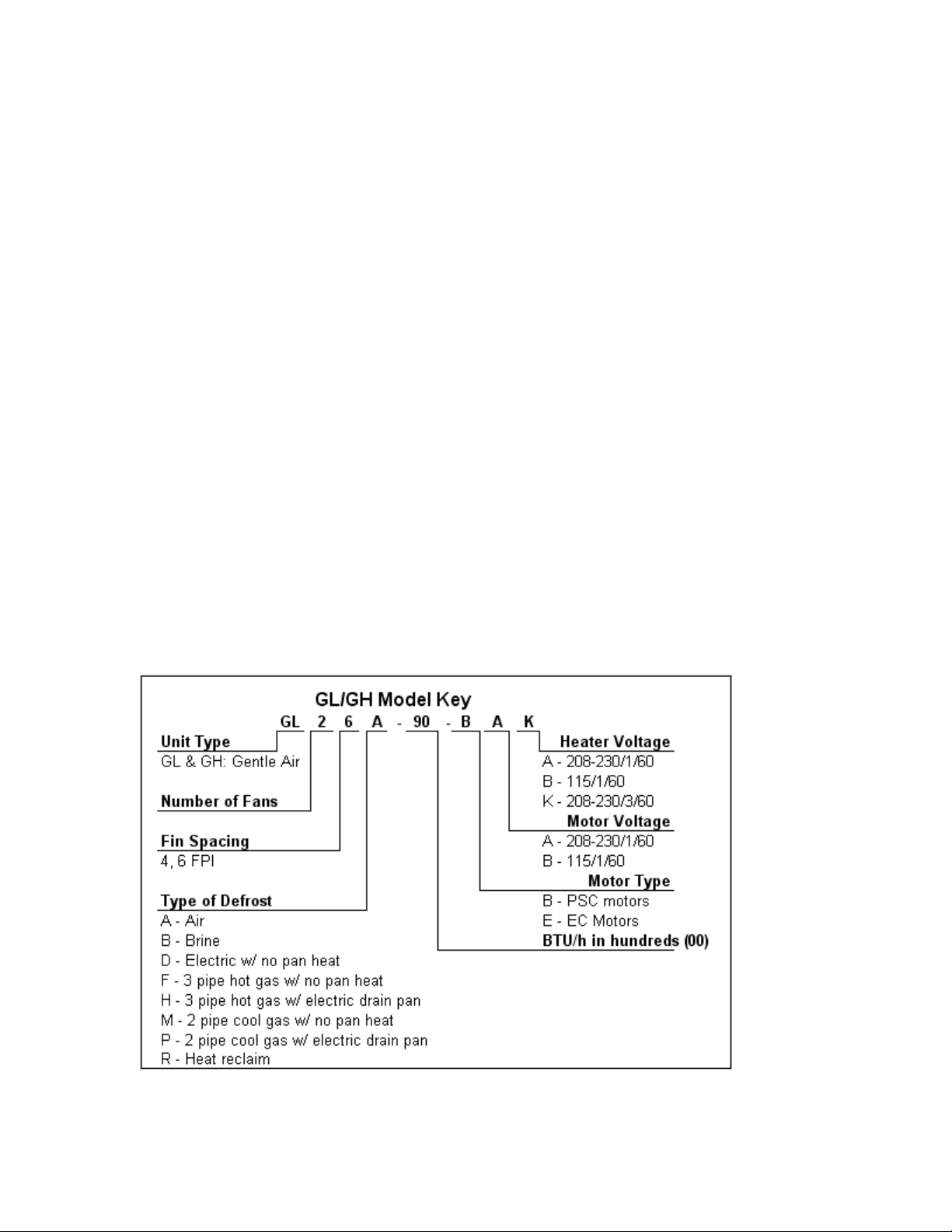
2.1 MODELS COVERED
GL Series Low Silhouette Unit Coolers.
GH Series High Silhouette Unit Coolers
The GL and GH series are designed for medium temperature low air circulation application in spaces
above 20°F (-6.7°C). GL/GH unit coolers blow air uniformly through twin coils creating a low velocity
“umbrella” air distribution.
The GA series has three defrost options – air, electric and hot gas. The GA series is designed to be install
level and tight to ceiling.
GL/GH –Gentle-Air Series Unit Coolers (E104493_B)
3
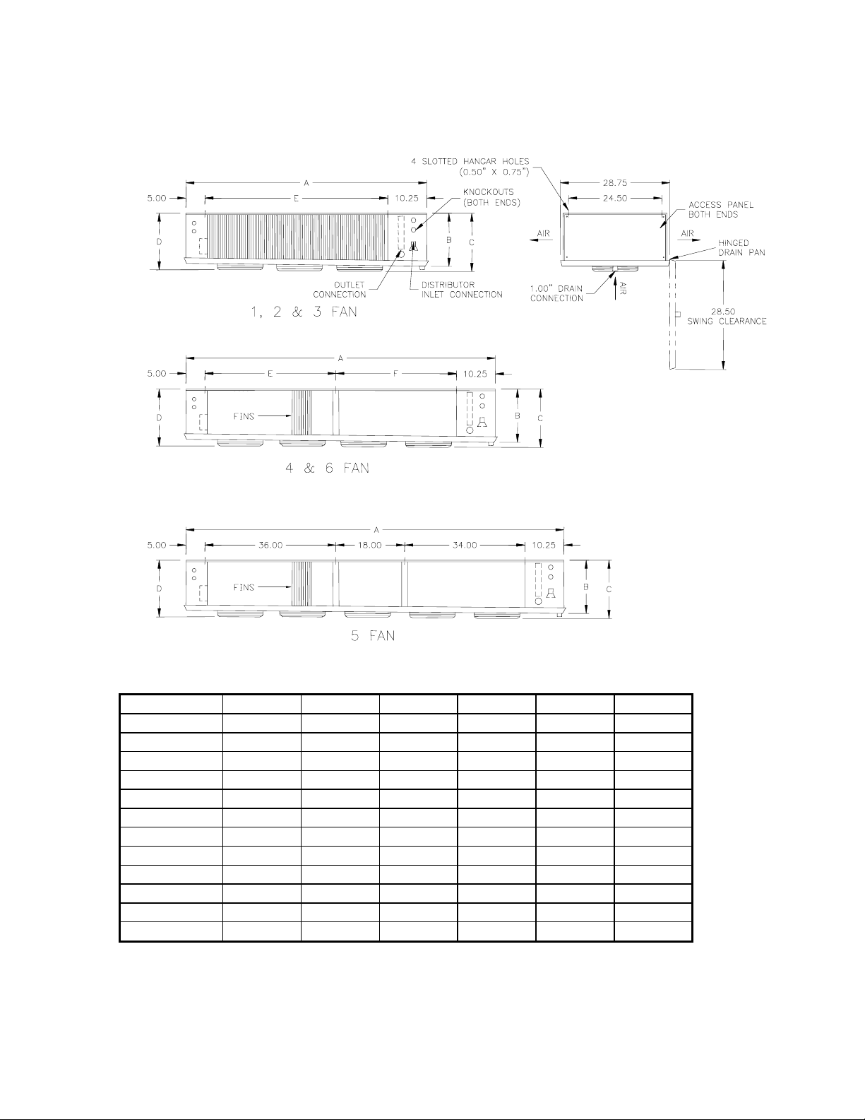
2.2 UNIT DIMENSIONS
Figure 1
Table 1 UNIT DIMENSIONS
Unit Size A B C D E F
GL-1
GL-2
GL-3
GL-4
GL-5
GL-6
GH-1
GH-2
GH-3
GH-4
GH-5
GH-6
31.75 10.50 12.25 11.38 16.00 -
49.75 10.50 12.25 11.38 34.00 -
67.75 10.50 12.25 11.38 52.00 -
85.75 10.50 12.25 11.38 36.00 34.00
103.75 10.50 12.25 11.38 - -
121.75 10.50 12.25 11.38 54.00 52.00
31.75 16.50 18.25 17.38 16.00 -
49.75 16.50 18.25 17.38 34.00 -
67.75 16.50 18.25 17.38 52.00 -
85.75 16.50 18.25 17.38 36.00 34.00
103.75 16.50 18.25 17.38 - -
121.75 16.50 18.25 17.38 54.00 52.00
GL/GH –Gentle-Air Series Unit Coolers (E104493_B)
4

3 UNIT LOCATION AND MOUNTING
3.1 UNIT LOCATION
Unit coolers must be located to provide good air circulation to all areas of the cooler. The unit cooler
should be positioned to allow for even airflow on both sides of the coil. Light fixtures, shelving and
product boxes must be located so that they do not block the air intake or air discharge from the unit
cooler.
IMPORTANT:
The coil face must be located a minimum of 12” from walls.
3.2 MOUNTING
The unit cooler should be suspended with 3/8” diameter hanger rods or flush mounted against the ceiling
using 3/8” minimum lag screws with flat washers. Rods should have double nuts on the top and bottom.
Adequate support must be provided to hold the weight of the unit.
The unit must be level in all directions to insure proper drainage of the condensate. Where N.S.F.
requirements must be met, unit cooler must be flush and sealed to ceiling.
4 PIPING INSTALLATION
4.1 DRAIN LINE
The drain line should be as short and as steeply pitched as possible with a minimum of ¼” drop per
running foot. A drain line trap should be installed to prevent warm moist air from migrating through the
drain line. Where multiple units are installed and share a common drain line but are defrosted
independently from one another, each unit should have its own trap before it enters the common drain
line.
If the temperature surrounding the drain line and trap is below freezing (32°) it must be wrapped with a
drain line heater and insulation. Be sure to also wrap the drain pan coupling. The drain line heater must
be energized continuously. Be sure to follow the manufacturer’s recommendation when installing the
drain line heat tape.
A union at the drain connection in the drain pan is recommended for ease of installation and future
servicing. The union should be located as close to the drain pan as possible. Use two wrenches when
tightening to prevent the drain fitting from twisting and damaging the unit.
Long runs of drain line, i.e. more than a few feet should be supported by hangers to avoid damage to the
drain pan.
4.2 REFRIGERATION PIPING
System design must conform to all local and national codes, laws and regulations applying to the site of
installation. In addition the safety code for mechanical refrigeration, ASME B31.5, should be followed as
a guide to safe installation and operation practice.
Refrigerant line sizes and piping techniques should be obtained from the ASHRAE guide or equivalent
reference. Under no circumstances should the refrigerant connection size of the unit be used as the basis
for sizing the lines.
The horizontal suction line should slope away from the unit cooler toward the compressor. Vertical
suction risers may require a trap at the bottom of the riser for proper oil return.
GL/GH –Gentle-Air Series Unit Coolers (E104493_B)
5
When connecting multiple unit coolers in series using a common suction line, the branch suction lines
must enter the top of the common suction line. The branch lines must be sized for the evaporator capacity
and the common suction line to be sized for the total system capacity.
For Food Service installations – seal any joint between unit cooler and cooler wall with a sealant Listed
by the National Sanitation Foundation.
For units with hot gas defrost refer to section 4.4 and figures 2 and 3 for piping arrangement.
Refer to section 4.5 for refrigerant distributor nozzle selection.
Refer to section 4.6 for expansion valve selection.
4.3 EVACUATION AND LEAK TEST
When all refrigeration connections have been completed, the entire system must be tested for leaks and
then evacuated. Refer to the instructions provided with your systems condensing unit for information on
performing the leak test and evacuation.
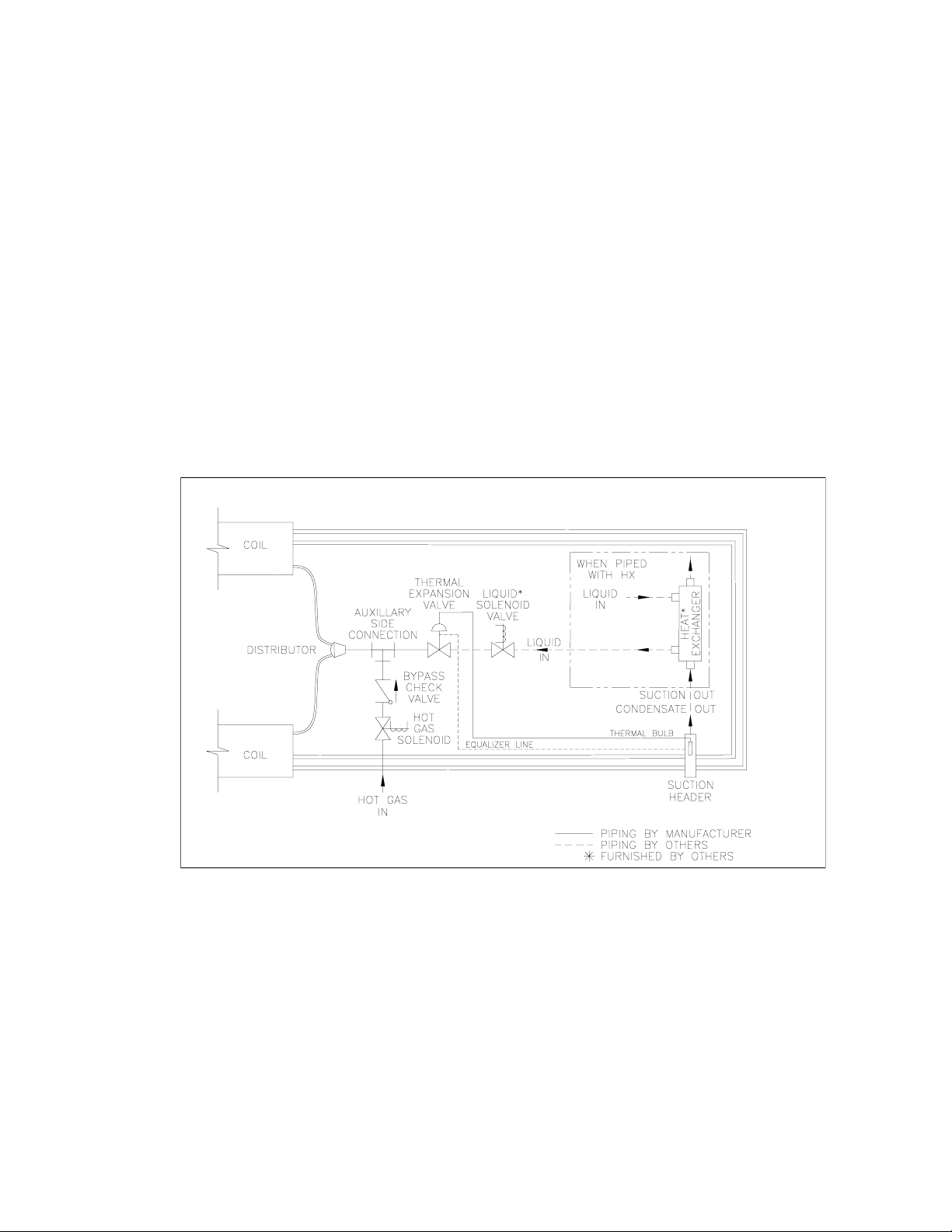
4.4 GL/GH HOT GAS DEFROST PIPING
Figure 2 F(HG) & H(HGE) 3 PIPE HOT GAS DEFROST COIL
GL/GH –Gentle-Air Series Unit Coolers (E104493_B)
6
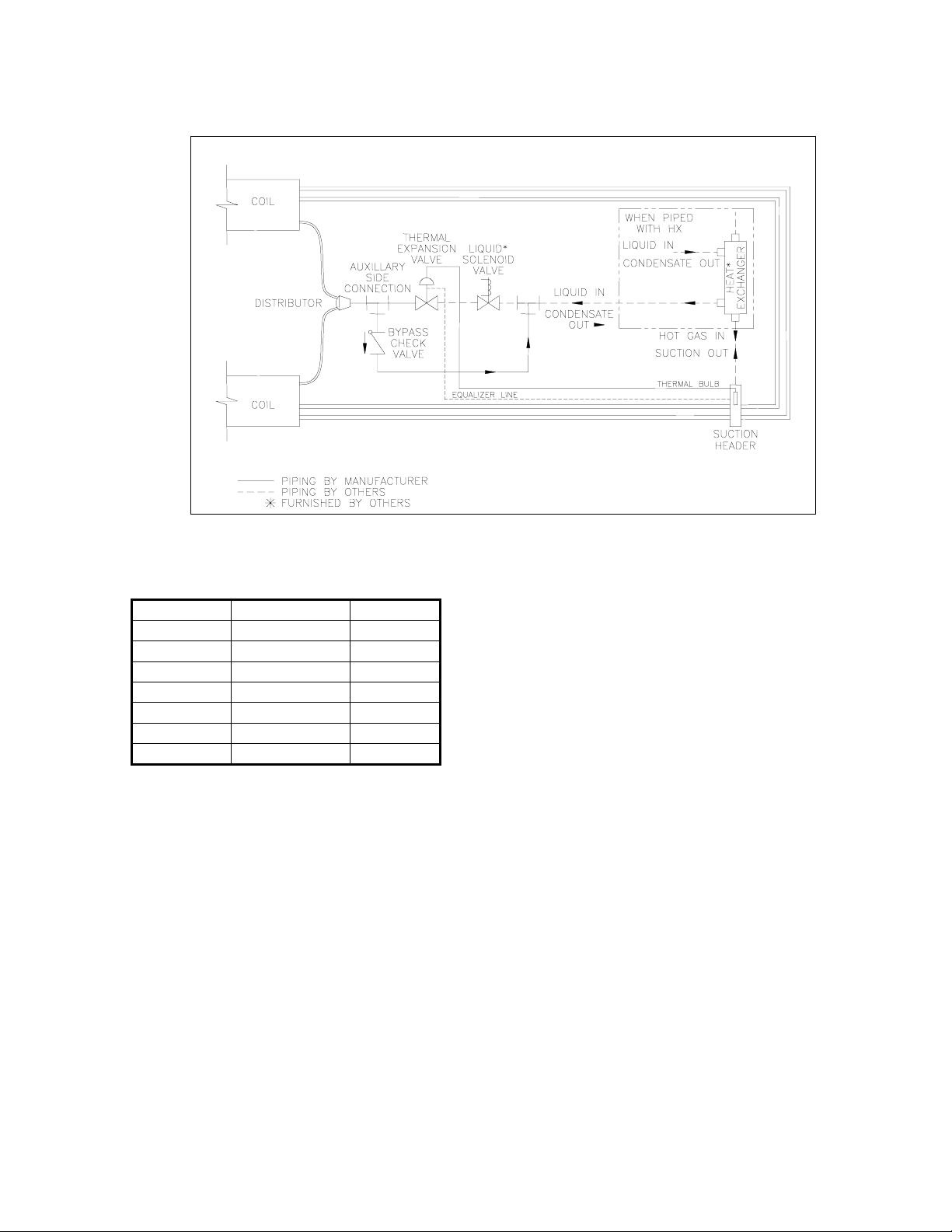
Figure 3 M(KG) & P(KGE) 2 PIPE REVERSE CYCLE HOT GAS DEFROST
Table 2 SUCTION CONNECTIONS
GL 2 CIRCUIT 0.875”
GL 4 CIRCUIT 1.125”
GL 6 CIRCUIT 1.125”
GH 2 CIRCUIT 0.875”
GH 4 CIRCUIT 0.875”
GH 6 CIRCUIT 1.125”
GH 8 CIRCUIT 1.125”
GH 10 CIRCUIT 1.375”
To identify number of circuits per model refer to tables 3 and 4.
4.5 REFRIGERANT DISTRIBUTOR NOZZLES
Unit coolers are piped using a refrigerant distributor with a changeable nozzle design to equally
distribute refrigerant to each circuit of the evaporator coil. Distributor nozzles are included and are
packed in individual plastic envelopes along with a retainer ring and instruction card. The instruction
card tells what refrigerant the nozzle is to be used with. There may be 1, 2 or 3 envelopes with nozzles
located near the distributor.
The nozzles provided with the unit have been selected for design conditions of 9°F to 11°F T.D. and 90°F
(85°F electric and hot gas defrost) liquid refrigerant at the expansion valve inlet. If the unit will be
operated at conditions that are substantially different from these conditions it may be necessary to select a
different size nozzle. Contact the factory for advice.
The nozzle must be installed in the distributor or the auxiliary side connector before installing the
expansion valve. There are nozzle identification numbers stamped on one side of the nozzle. Be sure to
insert the nozzle into the distributor with these numbers visible in case identification is required later.
GL/GH –Gentle-Air Series Unit Coolers (E104493_B)
7
 Loading...