

Page 1
Page 2

ACD320 user manual Preface
Before wiring, please make sure to cut off the power.
The electronic components in the inverter are sensitive to static, so please do not put
After cutting off the AC power supply, if the indicator light still on, please do not
The terminals of inverter must be connected to the ground correctly.
The Input power line absolutely can not be connected to the Output terminal U/T1
、
Preface
This manual is helpful for type selecting, installation, parameter setting, site commissioning,
rubleshooting, and daily maintenance of the inverter. To guarantee safe operation of the inverter,
please read this manual thoroughly, and keep it handy for referance in the future..
First use this product:
For those users who use this product for the first time, should read this manual thoroughly.
If you have any question in the Function and Functional performance, please feel free to contact
our technical support personnel for assist.
Notice:
anything in the inverter, and do not touch the main circuit board.
touch the circuit and any part in the inverter, beacause there still be high voltage in the
inverter which is very dangerous.
V/T2 and W/T3.
Application range of this manual:
This manual is applied to ACD320 Series Inverters of our company.
Page 3

ACD320user manual Catalogue
Chapter 1 Safety information and use notice points
1.1 Safety precautions
1.2 Use range
...........................................................................................................
1.3 Use notice points
1.4 Scrap notice points
Chapter 2 Type and specification of the inverter
2.1 Incoming inverter inspect
2.2 Type explanation
2.3 Nameplate explanation
2.4 Series type explanation
2.6 Out size
...............................................................................................................
2.7 Product technic index and specification
Chapter 3 Installation and wiring
3.1 Installation ambient
..........................................................................................
.............................................................................................
.........................................................................................
.........................................
.............................................................................
..............................................................................................
..................................................................................
.................................................................................
...............................................
....................................................................
......................................................................................
...................................
1
1
2
2
3
4
4
4
4
5
8
11
16
16
3.2 Electrical Installation
3.3 BasicWiring Diagram
3.4 Main Circuit Terminals andWiring
3.5 Control Terminals and Wiring
3.6 EMC Issues
Chapter 4 Digital Keypad Operation
........................................................................................................
4.1 Description of the DigitalKeypad
4.2 Modify and Check the Function Codes
4.3 How to View Status Parameters
4.4 Password Setting
........................................................................................
........................................................................................
...................................................................
..........................................................................
..............................................................
.............................................................
...................................................
...............................................................
..............................................................................................
4.5 Auto Tuning of Motor Parameters(Referto F1.11)
Chapter 5 Function parameters list
...............................................................
...............................
17
20
23
24
30
33
33
34
35
35
36
38
Page 4

ACD320user manual Catalogue
5.1 Symbol description
5.2 Function parameter schedule graph
Chapter 6 Parameter Description
6.1 F0 Basic Function Parameters
6.2 F1 Motor Parameters
......................................................................................
.......................................................
................................................................
..................................................................
...................................................................................
6.3 F2 Input and Output Terminal Function Parameters
6.4 F3 Human Machine Interface Parameters
6.5 F4Application Function Parameters
6.6 F5 Protection Parameters
6.7 F6 Communication Parameters
6.8 F7 Senior Function Parameters
..........................................................................
................................................................
................................................................
6.9 F8 Supplementary function Parameters 1
6.10 F9 Supplementary function Parameters 2
Chapter 7 Fault Diagnosis and Countermeasures
.............................................
........................................................
..........................................
........................................
...................................
..........................
38
38
54
54
64
69
78
82
92
95
98
103
106
109
7.1 Failure and countermeasure
7.2Fault and Countermeasures
7.3 Failure record lookup
7.4 Failure reset
Chapter 8 Maintenance
.................................................................................................
8.1 Routine maintenance
................................................................................
................................................................................
................................................................................
8.2 Inspection and replacement of damageable parts
8.3 Repair guarantee
8.4 Storage
Chapter 9 Appendix
..........................................................................................................
........................................................................................
..........................................................................................
...................................................................
....................................................................
..........................
Appendix 1 ACD320 series serial communication protocol
.................
109
114
125
125
126
126
126
127
127
129
129
Page 5

ACD320user manual Catalogue
Appendix 2 All BrakingResistors & Braking Units Use in AC Drives
.................................................................................................................................
Appendix 3 Parameter illustration of the inverter specially used for
one driving one constant pressure water supply
....................................
Appendix 4 Example for one driving two constant pressure water
supply controlling card and water supply mode that one for use and
one for supplement(one driving two circularly running
..................
)
143
144
147
Page 6
ACD320 User Manual Safety information and use notice points
1
Chapter 1 Safety information and use notice points
There are three kinds of safety relevant warnings in this service manual.They are as
follows:
This symbol briefs on: if do not operate as request, the body injured or equipment
damaged may occur.
This symbol is briefed on useful information.
This symbol briefs on: if do not operate as request, death, severely injured or serious
property loss may occur.
(1) Forbid to connect U/T1、 V/T2、 W/T3 output end to AC power supply, otherwise cause the totally
damageof theinverter.
(2) Don’t make DC- and P2 or DC+ short-circuited, otherwise cause the inverter to be damaged.
(3) The inverter is forbidden to install on flammables, otherwise have the danger of fire.
(4) Don’t install it in the environment with explosive gas,otherwise have the risk of explosion.
(5) After connecting main loop, should carry on insulating treatment to bare wiring end , otherwise
have danger of getting an electric shock.
(6) If being connected to the power supply, don’t operate the inverter with moist hands, otherwise
have danger of getting an electric shock.
(7) The ground terminal of the inverter must be grounded well.
(8) Inverter being connected to power supply, please don’t open cover and carry on wiring, Can
connect the wire or the check only after closing power for 10 minutes.
(9) Only qualified personnel may carry on wiring and forbid leaving over any conductive thing in
machine, otherwise have danger of gentting an electric shock or causing damage of the inverter.
(10) inverter stored for 2 years, should be stepped up gradually with voltage regulator first while having
the electricity ,otherwise have danger of getting an electric shockor explosion.
(1) It is prohibited that conncet AC 220V signal to control ends except RA, RB, RC, TA, TB, TC,
otherwise have danger of damaging property.
(2) If the inverter is damaged or without all parts, please don’t install and operate it, otherwise have
danger of fire or cause personnel injury.
(3) In the process of installation, should choose a place where can lay up the inverter, otherwise have
danger of personnel injury or property damage while falling down.
Note
!
!
In order to ensure the safety of your personal and equipment, please read this chapter of
content conscientiously before using the inverter .
1.1 Safety precautions
- -
Page 7

ACD320 User Manual Safety information and use notice points
1.2 Use range
(1) This inverter is only suitable for three phases AC asynchronous motor in general
industrial field.
(2) When apply inverter to such equipments that arerelated much to the life, great
property, safety devices etc., please must handle cautiously and consult producer.
(3) This inverter belongs to the control device of general industrial motor, if used in
dangerous equipments, must consider the security safeguard procedures when the inverter
breaks down.
1.3 Use notice points
(1) ACD280 series inverter is voltage-type inverter, so temperature, noise and vibration
slightly increasing compared to power source running when using, belongs to normal
phenomenon.
(2) If need to run for a long time with constant torque of low-speed, must select motor
of frequency conversion. To use general asynchronous AC motor when running at a low
speed should control temperature of the motor or carry on heat dissipation measure forcedly,
so as not to burn the generator.
(3) Such mechanical devices such as gearbox and gear wheel need lubrication. After
running at a low speed for a long time, may be damaged because the lubrication result
become poor, so please take necessary measures in advance.
(4) When the motor running with frequency above specified, besides considering the
vibration, noise increase of the motor, must also conform speed range of the motor bearing
and the mechanical device.
(5) For hoist and great inertia load, the inverter would shut off frequently due to
over-current or over-voltage failure in order to guarantee normal work. At this time, should
consider to choose the proper brake package.
(6) Should switch on/off the inverter through terminal or other normal order channels. It
is prohibited that switch on/off the inverter frequently by using strong electric switch such as
magnetic control conductor, otherwise will cause the equipment damage.
(7) If need to install such switch as the magnetic control conductor, etc. between
inverter output and the motor, please guarantee the inverter is switched on/off without output,
otherwise may damage the inverter.
(8) The inverter may meet with mechanical resonance of the load within certain range
of frequency output, can set up jumping frequency to evade.
(9) Before using, should conform the voltage of the power is within the working voltage
- 2-
Page 8
ACD320 User Manual Safety information and use notice points
ACD320
After wiring, short-circuit
U, V, W to measure
insulation resisitance.
1.4 Scrap notice points
U
V
W
M
ACD320
Megohm meter
Grounding part
UVW
Motor
range allowed, otherwise should vary voltage or order special inverter.
(10) In the condition of altitude above 1000 meters, should use the inverter in lower
volume, reduce output current by 10% of specified current after each 1500 meters height
increasing.
(11) Should make insulation check to the motor before using it for the first time or after
a long time placement. Please inspect with 500V voltage-type megohm meter according to
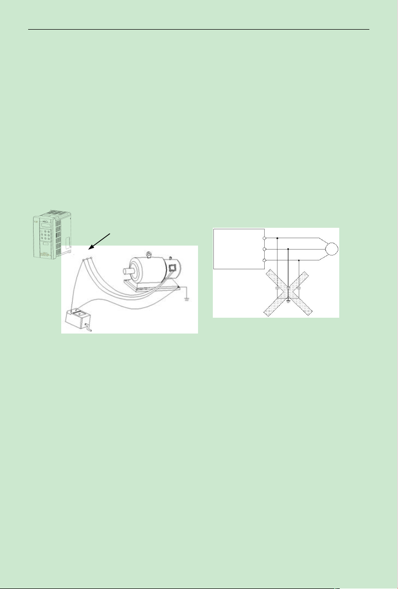
method shown as graph 1-1 and insulation resistance should not be smaller than 5MΩ,
otherwise inverter may be damaged.
(12) To forbid assembling capacitor for improving power factor or lightning proof
voltage-sensible resistance etc., otherwise will cause malfunction trip of the inverter or
damage of the parts, show as graph 1-2
Fig.1-1 motor insulation measure Fig.1-2 capacitor at output forbidden
When disposing scrap inverter and its parts, please note:
(1) The unit: please discard as industrial useless.
(2) Electrolytic capacitor: when burning the inverter electrolytic capacitor in it may
explode.
(3) Plastic: when plastic, rubber parts etc. in the inverter are burning, they may bring bad,
poisonous gas, so please be ready to safeguards.
- 3-
Page 9
ACD320 User Manual Type and specification of the inverter
4
Chapter 2 Type and specification of the inverter
2.1 Incoming inverter inspect
(1) Check if there is a damage during transportation and inverter itself has damage or
fall-off parts
(2) Check if parts presented in packing list are all ready.
(3) Please confirm rated data of the inverter is in line with your order requirement.
Our product is guaranteed by strict quality system during manufacturing, packing,
transportation etc,. please contact our company or local agent rapidly if some careless omission
or mistake arise, we’ll deal with it as soon as possible.
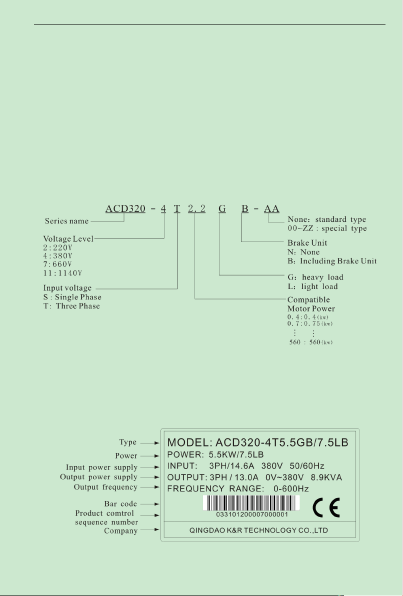
2.2 Type explanation
Fig.2-1 type explanation
2.3 Nameplate explanation
Nameplate presented as figure 2-2 with type and rating data at the bottom of inverter right
side
Fig. 2-2 Nameplate
- -
Page 10

ACD320user manual Type and specification of the inverter
Inverter type
Input
voltage(V)
Rated power
(KVA)
Rated input
current(A)
Rated output
current(A)
Adapted
motor(KW)
Three phase
380V
range::
-15%~20%
2.4 Series type explanation
Table 2-1 series type explanation
ACD320-2T0.4
ACD320-2S0.4
ACD320-2T0.7
ACD320-2S0.7
ACD320-2T1.5
ACD320-2S1.5
ACD320-2T2.2
ACD320-2S2.2
ACD320-2S3.7 5.7 31.5 15.0 3.7
ACD320-2S4.5 6.9 39 18.0 4.5
ACD320-2S5.5 7.6 44 20.0 5.5
ACD320-2S7.5 11.4 65 30.0 7.5
ACD320-4T0.7
ACD320-4T1.5 3.0 5.0 3.8 1.5
ACD320-4T2.2 4.0 5.8 5.1 2.2
ACD320-4T3.0 4.9 8.3 6.8 3.0
ACD320-4T4.0 5.9 10.5 9.0 4.0
ACD320-4T5.5 8.9 14.6 13.0 5.5
ACD320-4T7.5 11.0 20.5 17.0 7.5
ACD320-4T11 17.0 26.0 25.0 11
ACD320-4T15 21.0 35.0 32.0 15
ACD320-4T18.5 24.0 38.5 37.0 18.5
ACD320-4T22 30.0 46.5 45.0 22
ACD320-4T30 40.0 62.0 60.0 30
ACD320-4T37 57.0 76.0 75.0 37
ACD320-4T45 69.0 92.0 91.0 45
ACD320-4T55 85.0 113.0 112.0 55
ACD320-4T75 114.0 157.0 150.0 75
ACD320-4T90 134.0 180.0 176.0 90
ACD320-4T110 160.0 214.0 210.0 110
Three phase
220V range:
-15%~20%
1.0 5.4 2.3 0.4
1.5 8.2 4.0 0.75
3.0 14.0 7.0 1.5
4.0 23.0 9.6 2.2
1.5 3.4 2.1 0.75
- 5-
Page 11

ACD320user manual Type and specification of the inverter
Inverter type
Input
voltage(V)
Rated power
(KVA)
Rated input
current(A)
Rated output
current(A)
Adapted
motor(KW)
Three phase
380V range:
-15%~20%
Three phase
660V range:
-15%~20%
ACD320-4T132
ACD320-4T160 231.0 307.0 304.0 160
ACD320-4T185 237.0 340.0 330.0 185
ACD320-4T200 250.0 385.0 377.0 200
ACD320-4T220 280.0 430.0 426.0 220
ACD320-4T250 355.0 468.0 465.0 250
ACD320-4T280 396.0 525.0 520.0 280
ACD320-4T315 445.0 590.0 585.0 315
ACD320-4T355 500.0 665.0 650.0 355
ACD320-4T400 565.0 785.0 725.0 400
ACD320-4T450 630.0 883.0 820.0 450
ACD320-7T132
ACD320-7T160 231.0 200.0 175.0 160
ACD320-7T185 240.0 218.0 198.0 185
ACD320-7T200 250.0 235.0 215.0 200
ACD320-7T250 355.0 265.0 260.0 250
ACD320-7T280 396.0 305.0 299.0 280
ACD320-7T315 445.0 350.0 330.0 315
ACD320-7T355 500.0 382.0 374.0 355
ACD320-7T400 565.0 435.0 410.0 400
ACD320-7T450 630.0 490.0 465.0 450
ACD320-7T500 700.0 595.0 550.0 500
ACD320-7T560 730.0 605.0 575.0 560
192.0 256.0 253.0 132
192.0 170.0 150.0 132
- 6-
Page 12
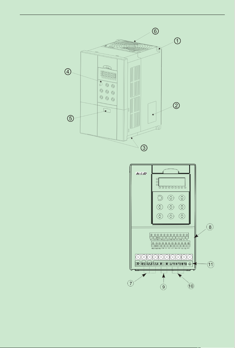
ACD320user manual Type and specification of the inverter
○1:Screw hole
○2:Nameplate
○3:Motor output terminal
lower-cover
○4:Operation surface
○5:Power input terminal
upper-cover
○6:Heat radiation vent
○7:Power input terminal
○8:External input/output
terminal
○9:Energy consumption
braking resistance terminal
○10:Motor output end
○11:Grounding end
2.5 Appearance and parts name explanation
Fig.2-3 parts name sketch
- 7-
Page 13
ACD320user manual Type and specification of the inverter
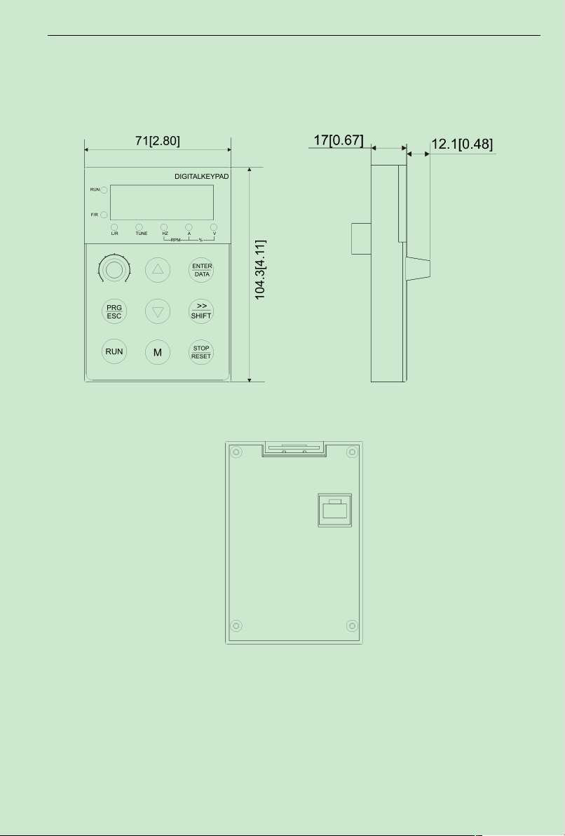
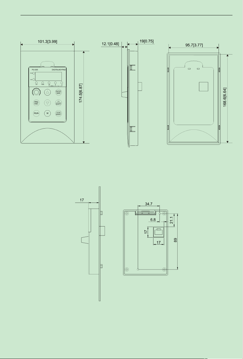
2.6 Out size
2.6.1 Keypad out size
For example:36.5[1.44] Unit:millimeter [inch]
Fig.2-4 Fig.a Outer dimension Fig.2-4 Fig.b Outer dimension
Fig.2-4 Fig.c Outer dimension
- 8-
Page 14
ACD320user manual Type and specification of the inverter
Out-pull panel indicatorA- using keypad sheath
Out-pull panel indicator B- not using keypad sheath
- 9-
Page 15
ACD320user manual Type and specification of the inverter
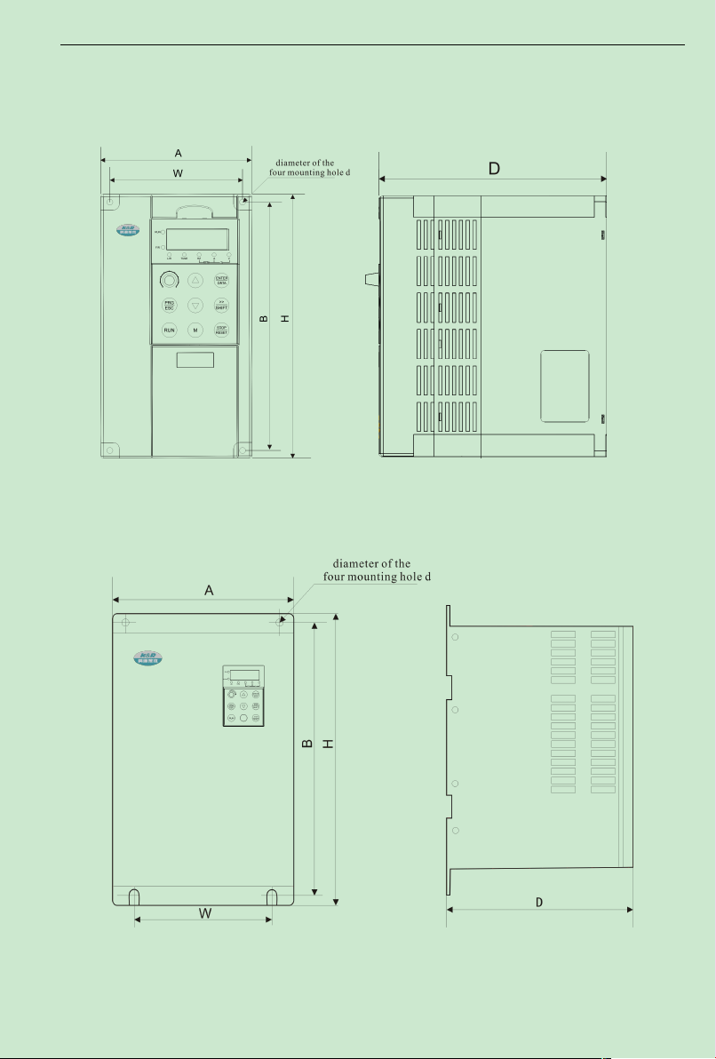
2.6.2 Chassis out size
2.6.2.1 Plastic chassis out size(wall mounted)
2.6.2.2 Metals chassis out size(wall mounted)
- 10-
Page 16
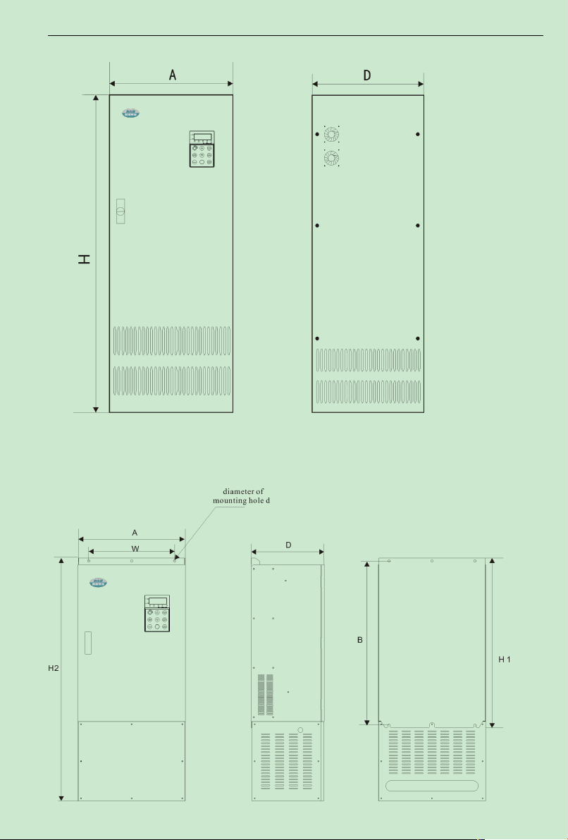
ACD320user manual Type and specification of the inverter
2.6.2.3 Metals chassis outline dimention drawing (clothes closet)
2.6.2.4 Metals chassis outline dimention drawing (the Cabinet machine and the wall hangs
machine)
- 11-
Page 17

ACD320user manual Type and specification of the inverter
Chassis
Specification and type
Size(mm)
Shell
ABHWD
d
E22
ACD320-2T0.4GB
ACD320-2S0.4GB
118.0
172.5
185.0
105.5
150.0
5.0
Plastic chassis
ACD320-2T0.75GB
ACD320-2S0.75GB
ACD320-2T1.5GB
ACD320-2S1.5GB
ACD320-4T0.75GB
ACD320-4T1.5GB
ACD320-4T2.2GB
ACD320-2T2.2GB
ACD320-2S2.2GB
170.0
ACD320-4T3.0GB/4.0
ACD320-4T4.0GB
E75
ACD320-4T5.5LB
160.0
235.0
247.0
148.0
186.0
5.5
ACD320-4T5.5GB/7.5
ACD320-4T7.5GB
E011
ACD320-4T11LB
210.0
322.0
336.0
150.0
200.0
7.0
Wall mounting Metals chassis
ACD320-4T11GB/15L
ACD320-4T15GB/18.5
ACD320-4T18.5G/22L
285.0 457.0 475.0 195.0 240.0 9.0
ACD320-4T22G/30L
ACD320-4T30G/37L
E037
ACD320-4T37G/45L
320.0
536.0
555.0
230.0
229.0
10.0
ACD320-4T45G/55L
E055
ACD320-4T55G/75L
410.0
611.0
634.0
320.0
236.0
12.0
ACD320-4T75G/90L
T090
ACD320-4T55G/75L
375.0
725.0
750.0
290.0
335.0
13.0
ACD320-4T75G/90L
ACD320-4T90G/110L
ACD320-4T110G/132L
500.0 765.0
H1:790.0
400.0 340.0 11.0
H1:th
e wall
hangs
machi
ne
H2:th
e
Cabin
et
machi
ne
ACD320-4T132G/160L
H2:1130.0
ACD320-4T160G/185L
685.0 - 1400.0 - 440.0 -
Clothes closet Metals
chassis
ACD320-4T185G/200L
ACD320-4T200G/220L
K400
ACD320-4T220G/250L
800.0-1600.0
-
550.0
-
ACD320-4T250G/280L
ACD320-4T280G/315L
ACD320-4T315G/355L
ACD320-4T355G/400L
ACD320-4T400G/450L
Size table
T030
E132
K200
- 12-
Page 18

ACD320user manual Type and specification of the inverter
K630
ACD320-4T500G/560L
1260.0-2290-620.0
-
ACD320-4T560G/630L
ACD320-4T630G/700L
Note:H1 is the height of wall mounted inverter, H2 is the height of clothes closet inverter.
Individualized
function
1kHz~ 15kHz;the carrier frequency will be automatically adjusted
according to the load characteristics.
Digital setting: 0.01Hz
Analog setting: maximum frequency ×0.1%
Open loop vector control (SVC)
V/F control
Open loop torque control
G model:0.5Hz/150%(SVC)
L model:0.5Hz/100%
G model: 150% rated current 60s; 180% rated current 1s.
L model: 120% rated current 60s; 150% rated current 1s.
Straight line or S curve acceleration/deceleration mode;
four kinds of acceleration/deceleration time;
acceleration/deceleration time ranges between 0.0s to 3600.0s
DC brake frequency: 0.00Hz to maximum frequency;
brake time: 0.0s to 50.0s, and brake current value: 0.0% to 150.0%.
2.7 Product technic index and specification
Item Specifications
Maximum frequency 600.00Hz
Carrier frequency
Input frequency
resolution
Control mode
Startup torque
Speed adjustment
range
Speed stabilization
precision
Torque control
precision
Overload capacity
Torque boost Automatic torque boost; manual torque boost 0.1% to 30.0%
V/F curve Two types: straight line and square type
Acceleration/decel
eration curve
DC brake
Jog control
Simple PLC and MS
Speed Running
Built-in PID It is easy to realize process-controlled close loop control system.
1:100(SVC)
±0.5%(SVC)
±15%(SVC)
Jog frequency range: 0.00Hz to 50.00Hz;
Jog acceleration/deceleration time: 0.0s to 3600.0s.
It can realize a maximum of 8 segments speed running via the
built-in PLC or control terminal.
- 13-
Page 19

ACD320user manual Type and specification of the inverter
Ru n
Three types of channels: operation panel reference, control terminal
reference and serial communication port reference. These channels can be
switched in various modes.
There are totally eight types of frequency sources, such as digital
reference, analog voltage reference, analog current reference, and serial
port reference etc.
These frequency sources can be switched in various modes.
There are five digital input terminals, one of which can be used as
high-speed pulse input. (The number of digital input terminals can be
expanded to ten) It can be compatible with active PNP or NPN input
mode.
There are two analog input terminals, one of which can be used only as
voltage input, while the other can be used as voltage or current input. (It
can expand one voltage input terminal)
There is one high-speed pulse output terminal (can be selected as open
collector mode), with square wave output of 0kHz to 50kHz. It can output
such physical parameters as setting frequency and output frequency.
One digital output terminal (can be expanded to two) One relay output
terminal (can be expanded to two) One analog output terminal (can be
expanded to two), with optional 0//4mA to 20mA or 0/2V to 10V. It can
realize the output of such physical parameters as setting frequency and
output frequency.
Display and
Keyboard
Operation
It can implement power-on motor short-circuit detection, input/output
phase loss protection, over current protection, over voltage protection,
under voltage protection, over heat protection and overload protection.
Auto voltage
regulation (AVR)
Torque limit and
control
Peripherals
self-detection upon
power-on
Shared DC Bus
Function
M key
running command
channel
Frequency source
It can keep constant output voltage automatically in case of change
of mains voltage.
“Digging machine” feature, which can limit the torque
automatically and prevent frequent over current tripping during the
running process; the close loop vector mode can implement torque
control.
It can conduct safety detections on the peripherals upon power-on,
including earth and short circuit detections.
It can realize the function that multiple inverters share the DC bus.
Programmable key: Select the command channel switching/forward
and reverse rotations/jog operation/up and down.
Input terminal
Output terminal
LED display It can display the parameters
protection function
- 14-
Page 20
ACD320user manual Type and specification of the inverter
Environment
Indoor, not bare to sunlight, not dust, no corrosive gas, no flammable gas,
no oil fog, no water drop or salt etc.
Must choose correct type, otherwise may cause abnormal running of the motor or damage
of the inverter.
Note
!
In order to give full play to the interver’s superior performance, please choose correct type
and check relevant content according to Chapter 2, then it can be used after wiring.
Using Place
altitude Lower than 1,000 meters
ambient temperature
Humidity Less than 95%RH, without condensing
Vibration Less than 5.9 m/s2(0.6g)
Storage temperature -20℃~+60℃
-10 ℃ Celsius to +40 ℃ Celsius (derated when used in the ambient
temperature of 40 ℃ Celsius to 50 ℃Celsius)
- 15-
Page 21
ACD320user manual Installation and wiring
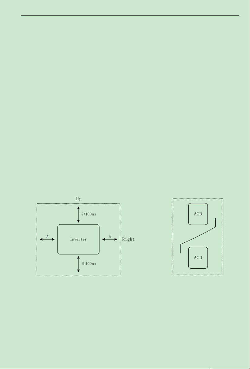
Note: No need to consider the dimension
Afor inverter of 22kWor below.
Ashall be bigger than 50mm for the
inverter of 22kWor above
Installation of single inverter
Note: Install an airflow- guidance
plate for the up and down installation
of inverters.
Up and down installation of inverters
Chapter 3 Installation and wiring
3.1 Installation ambient
3.1.1 Demand for installation ambient
(1) Installed in drafty indoor place, ambient temperature within -10ºC~40ºC, need external
compulsory heat sink or reduce the volume if temperature exceeds 40ºC.
(2) Avoid installing in place with direct sunlight, much dust, floating fibre and metal power.
(3) Forbid to install in place with corrosive, explosible gas.
(4) Humidity should be smaller than 95%RH, without condensation water.
(5) Installed in place of plane fixing vibration smaller than 5.9 m/s²(0.6G)
(6) Keep away from electromagnetic disturbance source and other electronic apparatus
sensible to electromagnetic disturbance.
3.1.2 Installation direction and place
(1) Normally the inverter should be mounted vertically, horizontal mounting will seriously
affect heat dissipation and the inverter must be used in lower volume.
(2) Demand for minimum mounting space and distance, please see Fig.3-1
(3) When install multiple inverters up and down, must apply leading divider between them,
see Fig.3-2
Fig.3-1 DZB Series Inverter Installation Location
- 16-
Page 22

ACD320user manual Installation and wiring
MODEL
ACD320
Series
Appli
cable
Motor
(KW)
INPUT(RST) Wire Size (mm2)
AirCircuit
Breakers
MCCB
Magnetic
Contactor
MC
Power
Terminal
DC
Reactor
Breaking
Terminal
Control
Terminal
2S0.4
2T0.4
0.4
DZ20-100(16A) CJ20-16
1.5
4
1.5
0.5~0.75
2S0.7
2T0.7
0.75
2.5 2.5
2S1.5
2T1.5
1.5
2S2.2
2T2.2
2.2
DZ20-100(32A) CJ20-40 4 6 4
2S3.7 3.7
4T0.7 0.75
DZ20-100(16A)
CJ20-16
1.5
4
1.5
4T1.5 1.5
2.5 2.54T2.2 2.2
4T4.0 3.7
4T5.5 5.5
DZ20-100(32A) 4
6
4
4T7.5 7.5
4T11 11
DZ20-100(50A) CJ20-40
6
4
4T15 15 8
8
4T18 18.5
10
4T22 22 DZ20-100(63A)
CJ20-63
164T30 30 DZ20-100(80A)
16
6
4T37 37
DZ20-100(100A) CJ20-100
4T45 45 25 25
4T55 55 DZ20-200(200A) CJ20-160 35 25*2(50)
The user shall focus on the heat dissipation issues when installing the inverter, and pay attention
to the following points:
1) Install the inverter vertically so that the heatmay be expelled from the top, but do not install
the inverter upside down.When twoVariable SpeedDrives are mounted up and dow n, an air flow
diverting plate should be fixed in between as shown in Fig. 3-1.
2) Installation space is shown in Fig.3-1 so as to ensure the heat dissipation space, but consider
the heat dissipation of other components when placing the inverter.
3) The installation bracket must be flame retardant.
4) Install the heat sink outside of the cabinet if the inverter is installed in the area with metal
powder. And in this case, the space inside the sealing cabinet shall be big enough.
3.2 Electrical Installation
3.2.1 Applicable devices and recommendablewiring of main circuit:
- 17-
Page 23

ACD320user manual Installation and wiring
4T75 75 25*2(50) 35*2(70) 10
4T90 90
DZ20-400(250A)
CJ20-250
35*2(70)
50*2(95)
16
4T110 110
50*2(95) 25
4T132 132
DZ20-400(350A) 70*2(150)4T160 160
4T185 185
4T200 200 DZ20-400(400A) CJ20-400 70*2(150) 70*2(150) 16*2(35)
4T220 220
DZ20-630(500A)
CJ20-630
95*2(185) 95*2(185)
25*2(50)
4T250 250
4T280 280
DZ20-630(600A) 120*2(240) 120*2(240)
4T315 315
4T355 355 DZ20-800(800A) CJ20-800 150*2(300) 150*2(300) 35*2(70)
4T400 400 DZ20-800(800A) CJ20-800 150*2(300) 150*2(300) 35*2(70)
4T450 450 DZ20-1250(1000A) CJ20-500*2 185*2(370) 185*2(370)
50*2(10
0)
4T560 560 DZ20-1250(1250A) CJ20-630*2 185*2(370) 185*2(370)
50*2(10
0)
4T630 630 DZ20-1250(1250A) CJ20-630*2 185*2(370) 185*2(370)
50*2(10
0)
- 18-
Page 24
ACD320user manual Installation and wiring
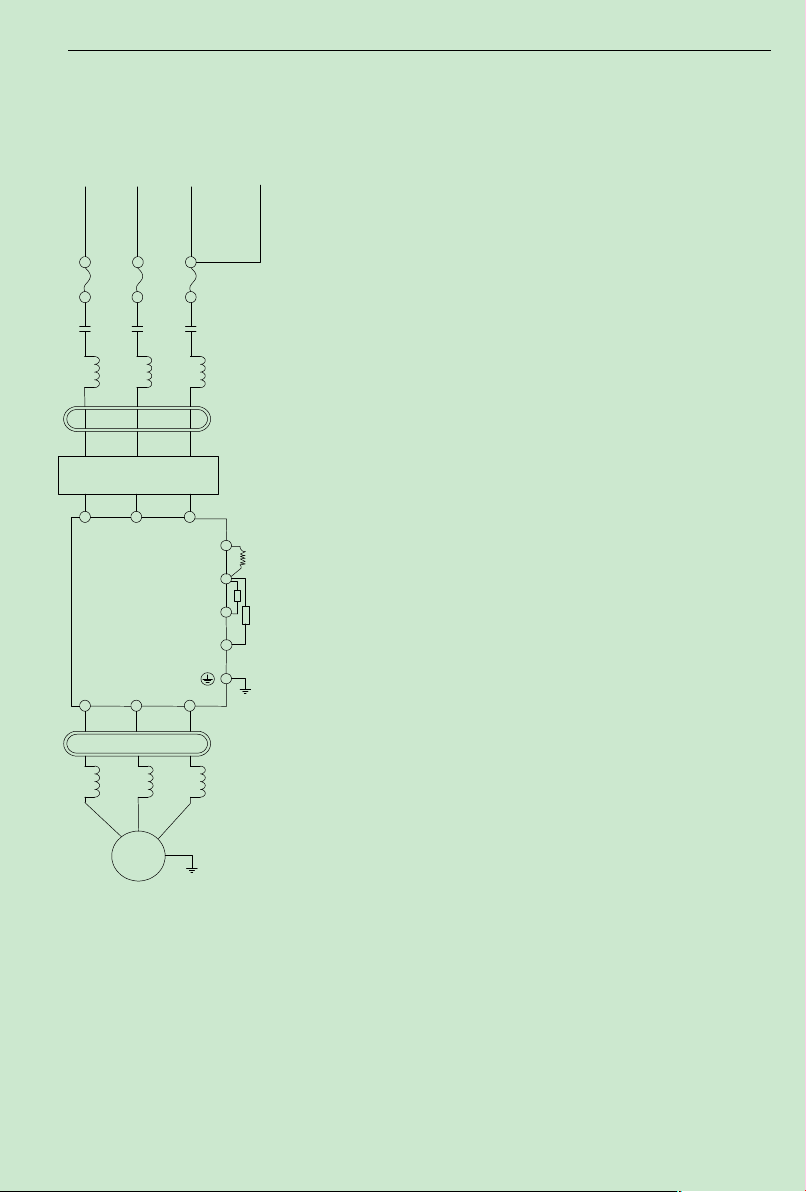
①Power supply:voltage levels:220V,400V。
②fuse or the Electric leakage chopper
Fuse or leaking current breaker
Please use fuse that conform to the rated voltage
and current level of inverter.
Be used to control the power of inverter, it palys
a role of protecting the inverter. Used to switch run and
stop is forbidden.
③Magnetic control conductor
Do not use magnetic control conductor for power switch
of the inverter, for which may reduce the inverter life.
④Input end AC reacter:
It can effectively restrain the harmonics of power supply wire,
or improve the power factor when the imbalance of main power supply
voltage is more than 3%(and the power capacity is larger than 500KVA
at the same time) or when power supply voltage changes dramatically.
⑤Radio interference filter
Nearby equipment, such as radio receiver, may brings electromagnetic
disturbance noise. The EMC radio interference filter is helpful for reducing
radio noise.
⑥EMI filter
Reduce the noise conducting by the power supply wire produced by
inverter.
⑦DC reactor
To inhibit high-order harmonics produced by inverter.
⑧Braking Resistors and braking Units
Improve braking Torque of inverter, or be used in occasions that ON/OFF
is operated frequently and rotatory inertia is great.
⑨Output end noise filter
Reduce the noise from output of inverter.
⑩Input end AC reacter:
Reduce the motor vibration caused by power supply switch waveform.
When wire between inverter and motor is long than 10 meters, which
Fig.3-2 Wiring of
Peripheral Equipment
R S T
P2
P1
B2
DC-
U V W
320
Series
inverter
M
~
Motor
Input power supply
①
②
③
④
⑤
⑥
⑦
⑧
⑨
⑩
3.2.2
周边设备配线图及其应用注意事项:
Wiring Diagram of Peripheral Equipment and the notice
- 19-
Page 25
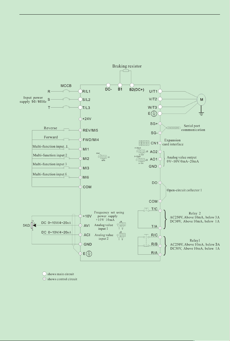
ACD320user manual Installation and wiring
3. 3 BasicWiring Diagram
Usersmust connect wires according to the following circuit diagram shown below.
Below 7.5KW
- 20-
Page 26
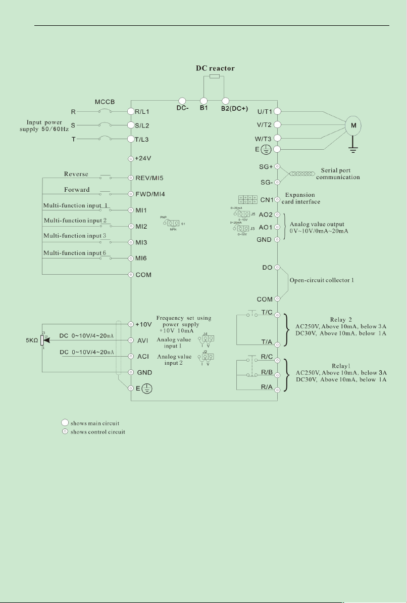
ACD320user manual Installation and wiring
11~30KW
:
- 21-
Page 27
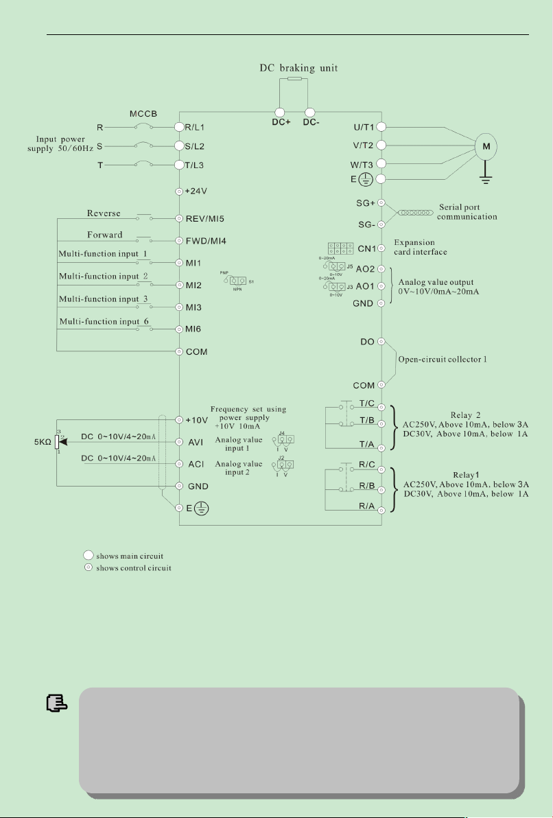
ACD320user manual Installation and wiring
提示
1、 T090、the Cabinet machine of E132、K200、K400 is Built in reactor;
2、 H1 is the height of wall mounted inverter, H2 is the height of clothes closet inverter.
2、E037、E055 is Selection of reactor;
3、The wall hangs machine of E132 is External standard reactor( ※The wall hangs machine of
E132 has to the outer reactor, The fault of not configued reactor is beyond the scope of the
Above 37KW
:
Fig.3-3 Basic running wiring diagram
Note
:
Breaking resistor terminals(B2/B1)for the inverter of 15KW or below.
Braking unitand and DC link reactor terminals(P1/P2/DC-)for the inverter 18.5KW~30KW.
Braking unitand terminals(DC+/DC-)for the inverter above 37KW.
- 22-
Page 28
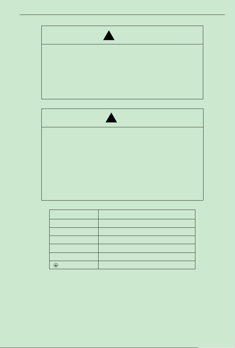
ACD320user manual Installation and wiring
Danger
Danger
R/L1、S/L2、T/L3 AC input line terminals
U、V、W Motor connection
B1、B2(DC+) Connection for the braking resistor (option)
P1/B2(DC+)、DC- Connection for the braking unit (option)
P1/B2(DC+)、P2 Connection for the DC Link Reactor (option)
E
Ground
!
!
3. 4 Main Circuit Terminals andWiring
★Wiring can only be done after the mains input is cut off, otherwise therewill be
danger of electric shock!
★Only qualified and trained engineer can perform thewiring, otherwise there will be
danger of electric shock!
★Grounding cable must be grounded, otherwise there will be danger of electric shock
or fire!
★Please confirmthe mains voltage level is same with that of the inverter, otherwise the
inverter may be damaged!
★Make sure the ratings of the drivenmotor are in compliance with the inverter,
otherwise the motor may be damaged or the inverter may be in protection status!
★Do not confuse the input terminals with the output terminals (U, V,W), otherwise
there will be danger of damaging the inverter!
★Brake resistor cannot be connected between the DC bus terminals (+) and (-),
otherwise fire may occur!
Main Circuit Terminals of Inverter
(1)
Terminals Description
(2)Notes on Wiring
A. Input power supply R/L1,S/L2 and T/L3:
There is no phase-ration requirement for the input of inverter.
B.DC bus P1/B2(DC+) and (DC-) terminals:
Pay attention that the DC bus terminals(P1/B2(DC+) and (DC-) still have voltage after power off,
and the user can only touch the terminals after the CHARGE LED turns off and the voltage is
below 36V, otherwise there is a danger of electric shock.
- 23-
Page 29

ACD320user manual Installation and wiring
Below 7.5KW
When selecting the brake unit for the inverter above 18.5kW,pay attention that the polarity of
(DC+) and (DC-) cannot be reverse, otherwise the inverter may burn or be damaged.
The cable length of brake unit shall be less than 10 mand twisted pair cables shall be used.
Do not connect the brake resistor directly to the DC bus, otherwise the inverter may burn or be
damaged.
C. Brake resistor terminals of B1、B2(DC+
)
The brake resistor terminal is effective only for the inverter of 15kW or below and has a built-in
brake unit. Select the recommended resistor with the cable length of less than 5m, otherwise the
inverter may burn or be damaged.
D. Inverter output U, V and W:
Inverter output terminals cannot connect to capacitors or surge snub devices, otherwise the
inverter may be in protective status or damaged.
If the cables between the motor and the inverter are too long, electrical resonance may occur due
to the distributed capacitance,whichmay result in damaging the motor insulation or big leakage
current, so if the cable length is longer than 100m,AC reactormust be installed.
E. Grounding Terminal :
GroundingTerminal must be connected to earth reliably and the grounding resistance shall be
less than 5Ω, otherwise the equipmentmay work abnormally or be damaged. Do not share the PE
and neutral line of themains supply.
3. 5 Control Terminals and Wiring
1)Layout of ControlTerminals(Fig.3-4,Fig3-5):
Above 11KW
Fig.3-4
Fig.3-5
- 24-
Page 30

ACD320user manual Installation and wiring
Item Symbol
Mu i ti - fu n ct i o n in p ut
te r mi n a l
MI1-COM
Multi-function
input terminal 1
Used for multi-function input
terminal, for detailed see Chapter
6 Section terminal function
parameter(F2 group) input end
function description.
MI4 factory default forward
running ,MI5 factory default
reverse running.
(common end: COM)
Optocoupler isolation
input
Input impedance: R=2KΩ
Max.input
frequency:200Hz
MI2-COM
Multi-function
input terminal 2
MI3-COM
Multi-function
input terminal 3
FWD(MI4)
-COM
Multi-function
input terminal 4
REV(MI5)
-COM
Multi-function
input terminal 5
power supply
Provide +24V power
supply.(negative pole: GND)
Max. output current:
50mA
+24V power supply(negative
pole:COM)
Max. output current:
200mA
Common end of
MI1,MI2,MI3,MI4,MI5,MI6
and reference ground of +24V
power supply.
Internal isolating between
COM and GND
Reference ground of analog
signal and +10V power supply.
An a lo g va l ue in p ut
Accept analog voltage,current
input,voltage, current optioned
by jumping-wire J4, factory
default is current. (reference
ground:GND)
Input voltage range:DC
0~10V(input
impedance:100KΩ)
Input current range:0~
20mA(input impedance:
500Ω);
Resolution:1/1000
Accept analog voltage/current
input,voltage, current optioned
by jumping-wire J2, factory
default is current. (reference
ground:GND)
Input voltage range:DC
0~10V(input
impedance:100KΩ)
Input current range:0~
20mA(input impedance:
500Ω);
Resolution:1/1000
2)Function of Control Terminals:
Name Function description spec
MI6-COM
+10V-GND
+24V-COM
COM
GND
AVI-GND
Multi-function
input terminal 6
+10V power
supply
+24V power
supply
+24V power
supply negative
pole
+10V power
supply negative
pole
Analog value input
1
ACI-GND
Analog value input
2
- 25-
Page 31

ACD320user manual Installation and wiring
An a lo g va l ue ou t pu t
Provide analog voltage/current
output, for detailed see F2.22
parameter description, output
voltage/current optioned by J3,
factory default output voltage.
(reference ground: GND)
Voltage output range:
0~10V
Current output range:
0~20mA
Provide analog voltage/current
output, for detailed see F9.09
parameter description, output
voltage/current optioned by J5,
factory default output voltage.
Voltage output range:
0~10V
Current output range:
0~20mA
Mu l ti - fu n ct i o n ou t pu t
te r mi n al
Used for multi-function switch
output terminal, for detailed see
Chapter 6 terminal function
parameter(F2 group) output end
function description.(common
end: COM)
Optocoupler isolation
output
Work voltage range:
15~30V
Max. output current:
50mA
Use method see
description of parameter
F2.20
Serial port
communica
tion
485 difference signal positive
end
For standard RS-485
communication interface,
please use twisted-pair or
shielded wire.
485 difference signal negative
end
Re l ay ou t p ut
te r mi n a l
Contact capacity:
AC250V,3A,
COSΦ=0.4。
DC 30V,1A
Contact capacity:
AC250V,3A,
COSΦ=0.4。
DC 30V,1A
Always-open terminal
As s is t an t
in t er f ac e
28PIN interface,connected to
selectable card
-
Connecting to native keypad or
wire of pull-out keypad
-
di a l
sw i tc h
Multi-function input NPN, PNP
input choice
Please refer to
“Description of control
terminal wiring” for
detail
AO1-GND
AO2-GND
DO-COM
SG+
SG-
R/A-R/B
R/A-R/C Always-open terminal
Analog value
output 1
Analog value
output 2
Open circuit
collector output
terminal
RS485 serial port
communication
Always-closed terminal
Relay output 1
T/A-T/B
T/A-T/C
CN1
3)Notes on Control Terminals:
A) Analog input terminal:
Since the weak analog voltage signal is easily disturbed by external disturbance source, shielded
Relay output 2
Expansion card
interface
J1
S1 NPN/PNP
Native keypad
interface
Always-closed terminal
- 26-
Page 32
ACD320user manual Installation and wiring
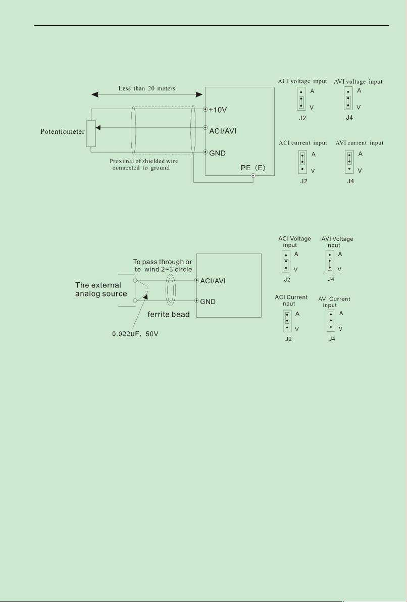
cable shall be used and the cable shall be as short as possible and the length shall not exceed 20m,
as shown in the figure 3-6:
Fig. 3 -6 Analog Input Terminal of ACD Series Inverter
If the analog signal is severely disturbed, filter capacitor or ferrite core shall be installed at the
analog signal source as shown in the Fig. 3-7
:
Fig. 3-7 Analog Input TerminalWith Filter devices
(2) Analog output terminal wiring
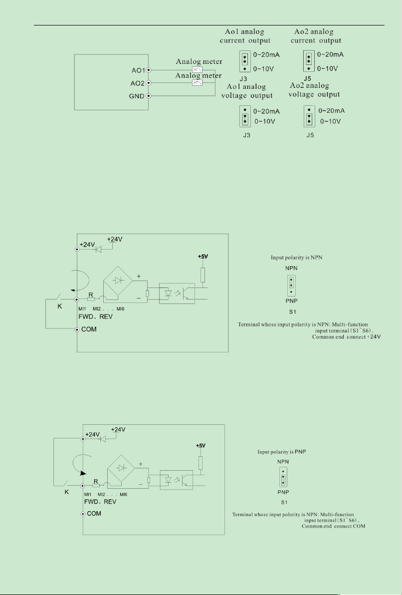
Analog output terminal AO1, AO2 connected to analog meter and kinds of physical
data can be indicated, thereinto AO1 can output current(0~20mA) or voltage(0~10V)
decided by jumping-wire J3, AO2 can output current(0~20mA) or voltage(0~10V) decided
by jumping-wire J5. Terminal wiring mode as Fig.3-8.
- 27-
Page 33
ACD320user manual Installation and wiring
B. Source(Drain) Electrode Connection
Fig.3-8 Analog output terminal wiring diagram
MI1~MI6、FWD、REV terminal wiring method
(3)
A. the mode of dry contact
Use interior 24V power supply, when input polarity is PNP,the wiring mode as
①
Fig.3-9.
Fig.3-9 Source Electrode Connection mode when using interior 24V power supply
Use interior 24V power supply, when input polarity is PNP,the wiring mode as
②
Fig.3-10.
Fig.3-10 Drain electrode connection mode when using interior 24V power supply
- 28-
Page 34
ACD320user manual Installation and wiring
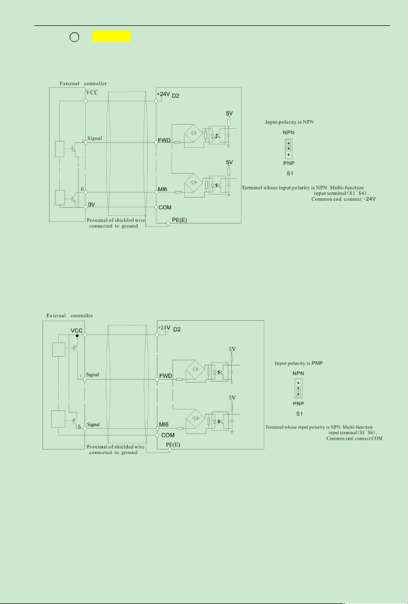
1 The use of inverter internal +24V power supply, external controller for
NPN typecommon emitter connection pole output,As shown in Figure 3-11
Fig.3-11 Source Electrode Connection mode when using interior 24V power supply
The use of inverter internal +24V power supply, external controller for
②
PNP typecommon emitter connection pole output,As shown in Figure 3-12
。
。
Fig.3-12 Drain electrode connection mode when using interior 24V power supply
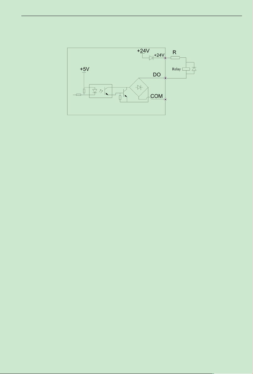
Number output terminal DO
(4)
When number output terminal need to drive the delay, absorber diode should be added to the
two sides of delay coil, else DC 24V power supply may be damaged.
Note: The absorption diode shall be installed with correct polarity, as shown in Fig.3-13.
- 29-
Page 35
ACD320user manual Installation and wiring
3.6.1 Influence ofHarmonics
1) The high frequency harmonics of mains supply will influence the rectifying circuit of the
inverter. The harmonics will heat the rectifying circuit and even damage the circuit. So, it is
recommended to install the filtering device in the environmentwhere the power quality is poor.
2)Since the inverter output has high frequency harmonics, the output cannot be installedwith
capacitor or surge suppressing devices because the capacitor and surge suppressing device may
resonate the circuit and damage the equipment.
3.6.2 EMI
1) Two kinds of EMI, one is the EMI around the inverter and disturbs the inverter. This kind of
EMI is weak, besides the inverter has been designed with strong immunity.Another is the EMI
from the inverter that may influence the equipment around the inverter. The inverter itself is a
disturbance source because it outputs PWM wave through high carrier frequency, so solving the
Otherwise, when the digital output terminal has output, the DC 24V power supply and output
circuit will be damaged immediately.
Fig.3-13 Schematic diagram for connection of digital output terminal
Delay output terminal RA/B/C、TA/B/C wiring
(5)
If driving an inductive load(such as the electromagnetic relay,the contactor), surgevoltage
absorption circuit should be installed, such as RC absorption circuit(Pay attention that its leaking
current should be less than keeper current of the contactor or relay controlled by it),
voltage-sensible resistance, and diode,etc.(If it is used in DC electromagnetic loop, check the
polarity when install). Component of absorption circuit should be installed on the two side of the
coil of delay or contactor.
3.6 EMC Issues
- 30-
Page 36

ACD320user manual Installation and wiring
EMI issue is mainly toreduce the EMI of inverter.
Methods:
A) Inverter and other equipment shall be well grounded and the grounding resistance shall be
less than 5ohm.
B) Inverter's power cables shall be vertical instead of parallel with the control cables.
C) For the applicationwith strong disturbance, the power cables from the motor to the inverter
shall be shielded and the shielding layer shall be grounded.
D) The cables of disturbed equipment shall be twisted shielded cables and the shielding layer
shall be grounded.
2) Reducing the disturbance to the inverter from other equipment
The relay, contactor or electronic -magnetic braking device will disturb the inverter.
Take the following actions to solve this issue:
A) Install surge suppressing devices to the disturbing device
B) Install filter to the input of the inverter
C) Inverter's control cables shall be shielded and the shielding layer shall be grounded
3)Method to reduce the disturbance fromthe inverter to the equipment
Two kinds of noises, one is the radiation from the inverter itself, and another is the radiation from
the cable between the inverter and the motor. These two kinds of radiations induce the cables of
the equipment and make the equipment work abnormally. Following method can be used:
A) If themeasuring meters, radio equipment and sensors and their signal cables are installed in a
cabinet together with the drive, these equipment cableswill be easily disturbed. Take the actions
below to solve the problem: The equipment and the signal cables should be as far away from the
inverter as possible; Signal cables and power cables shall not be routed in parallel or bound
together; The signal and power cables should be shielded; Install radio noise filter and linear
noise filter at the input and output sides of the inverter.
B) If the external equipment shares a sameAC supply with the inverter, and the above cannot
eliminate the disturbance, then the user should install a linear filter or a radio noise filter.
- 31-
Page 37

ACD320user manual Installation and wiring
C) Ground the external equipment and eliminate the disturbance of the leakage current fromthe
inverter's grounding cable.
3.6.3 Leakage current
The inverter has two kinds of leakage current, one is the grounding leakage current and another
is the leakage current between the lines:
1) Grounding leakage current:
The distributed capaci tance exists between the cables and the ground, and the bigger the
capacitance and the bigger the leakage current, so themotor cables should be as short as possible.
Besides, the bigger the carrier frequency is, the bigger the leakage current is, so the user can also
reduce the carrier wave frequency, but themotor noise may increase. Installing reactor can also
reduce the leakage current.
The leakage current is increasedwith the increase of the circuit current, so the leakage current is
big if the motor power is big.
2) Leakage current between lines:
The distributed capacitance exists in the inverter output cables, andresonancemayoccurifhigh
frequency harmonics exist in the current, thus the leakage current occurs, which may result in the
wrong action of relay.
The method to solve this issue is to reduce the carrier frequency or install the output reactor. It is
recommended to use inverter protection function instead of a thermal relay to protect themotor
before using the inverter.
- 32-
Page 38
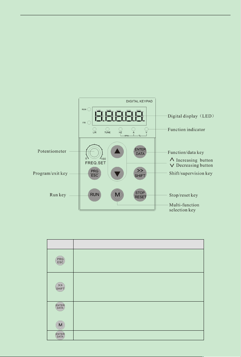
ACD320user manual Digital Keypad Operation
Chapter 4 Digital Keypad Operation
Fig. 4-1 Operation Panel Schematic Diagram
Table 4-1 keypad function table
Program /Esc
First-stage menu entry or exit
Under stop and run display interface, the display parameter can be
chosen by moving to the right circularly; when the parameter is
modified, its modified bit can be chosen, please refer to F3.05 ,
F3.06,F3.07
Under stop and run display interface, the display parameter can be
chosen by moving to the left circularly; when the parameter is
modified, its modified bit can be chosen, please refer to F3.05 ,
F3.06,F3.07
Enter into the next menu or setting parameter confirmation
4.1 Description of the DigitalKeypad
DigitalKeypad Parts and Functions
This digital keypad module includes two parts: display panel and a keypad.The display
panel allows the user to program the AC drive, aswell as view the different operating parameters.
The keypad is the user interface to the AC motor drive. Refer to the following figure for a
description of the different parts.
Key Description
+
- 33-
Page 39
ACD320user manual Digital Keypad Operation
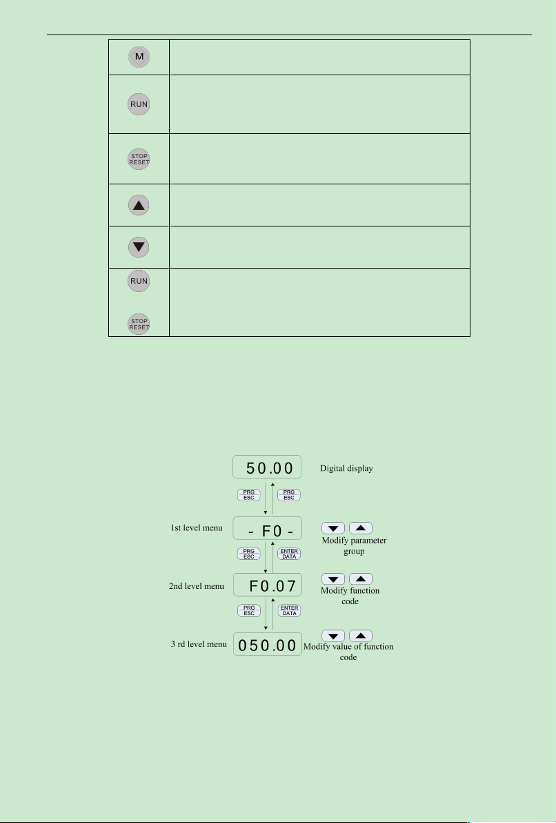
Refer to F3.02 for detailed operation method.
Enter into run under keypad mode
To press the key can stop the running inverter; it can also used to reset
the inverter when in malfunction alarm status, the function of the key is
restrictedby F3.03.
To increase data or function code(to press it continuously can improve
increasing speed)
To decrease data or function code(to press it continouously can
improve decrease speed)
When RUN key and STOP/RESET key are pressed at the same time,
the inverter
+
4.2 Modify and Check the Function Codes
ACD320 series inverter’s operation panel uses 3-level menu to conduct parameter settings.
3-level menu: function parameter group (first level) →function code (second level)
→setting of function code (third level). Operation procedure is shown in Fig. 4-2.
Note: When operating 3-level menu, pressing PRG/ESC or ENTER/DATA can return to second
level menu. The difference is: pressing ENTER/DATA will save the parameters and return to
second level menu and then shift to the next function code, while pressing PRG/ESC will return
to second level menu without saving the parameters.
Fig. 4-2 Operation Procedures for 3-level Menu
- 34-
Page 40
ACD320user manual Digital Keypad Operation
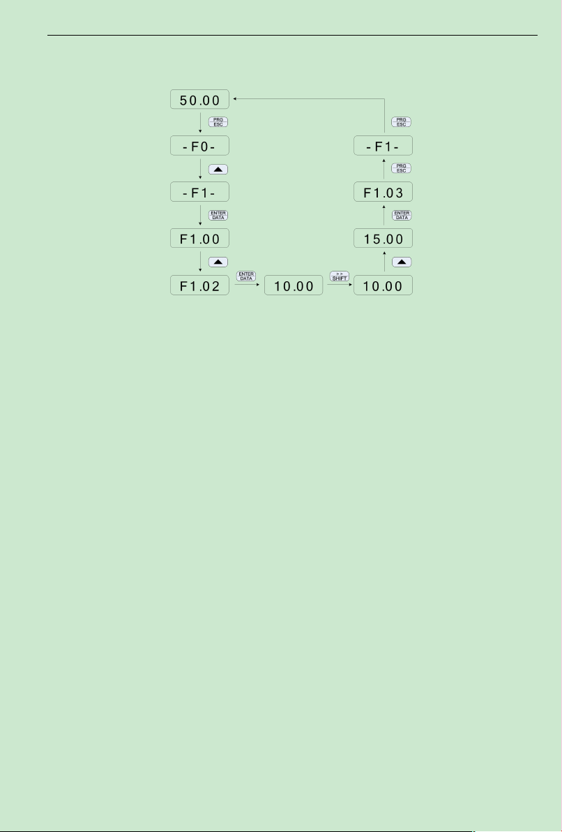
Example: Change the setting of F1.02 from 10.00Hz to 15.00Hz. (Bold means flash bit.)
Fig. 4-3 Example for Parameter Changing
In third level menu, if the parameter has no flash bit, it means the function code cannot be
changed and the possible reasons are:
1) This parameter of this function code cannot be changed, such as the actually detected
parameter and running record parameter.
2) This function code cannot be changed in operating status and can only be changed when
the inverter is stopped.
4.3 How to View Status Parameters
When ACDSeries inverter is in the stop or running status, several status parameter of the
inverter can be displayed on the LED nixie tube. The status can be chosen wether to display by
function code F3.05(running parameter)、F3.06 (stop parameter), please refer to the discrption of
F3.05 and F3.06 for detail. Pressing the key SHIFT can switch the display of stop or running
status parameters by moving to the right circularly, and pressing the key ENTER +M can switch
the display of stop or running status parameters by moving to the left circularly.
There are nine stop status parameters to be displayed in the stop status, Setting frequency,
DC bus voltage, Input terminal status,Output terminal status,PID setpoint,PID feedback, AVI
value, ACI value, segment of multi-speed , the function code F3.06 can decide these parameters
wether to display by bit. Pressing the key SHIFT can switch the display of the selected
parameters by moving to the right circularly, and pressing the key ENTER +M can switch the
display of the selected parameters by moving to the left circularly.
The inverter has fifteen running status parameters to be displayed in the running status, they
are running frequency, setting frequency, Output current,Output voltage, Running speed, Output
- 35-
Page 41

ACD320user manual Digital Keypad Operation
power, Output torque, DC bus voltage, PID setpoint, PID feedback, Input terminal status, Output
terminal status, AVI value, ACI value, current segment of multi-speed, setting torque, the
function code F3.05 can decide these parameters wether to display by bit. Pressing the key
SHIFT can switch the display of the selected parameters regularly.
If the inverter is powered on again after power-off, the parameters displayed are defaulted as
those selected before the power-off.
4.4 Password Setting
ACD320 inverter provides password protection for users. When F3.00 is not zero, that is
the user password, once exiting the function code editing status, the password protection function
is valid if there is no operation within one minute. If the userpresses PRG/ESC again, the inverter
shall display “0.0.0.0.0.”, and the user can only enter the menu after inputting the user password.
Otherwise, the user cannot enter.If the user wants to cancel the password protection function,
F3.00 should be set 0.
4.5 Auto Tuning of Motor Parameters(Referto F1.11)
Before running the inverter that has selected the vector control mode or open loop torque mode,
accurate motor nameplate parameters must be input to the inverter correctly. ACD320 inverter
will configure the standard motor parameters according to the nameplate parameters. Vector
control mode is highly dependent on the motor parameters and correct parameters must be
acquired for achieving good control performance.
Motor auto tuning procedures:
Firstly set the command source (F0.01) as the operation panel command channel.
Then input the following parameters according to the actual parameters of motor:
F1.01 Rated power of motor
F1.02 Rated frequency of motor
F1.03 Rated speed of motor
F1.04 Rated voltage of motor
F1.05 Rated current of motor
If the motor is disconnected from the load completely, select 1 (complete tuning) in F1.11, and
press RUN in keypad, the inverter will calculate the parameters below automatically:
F1.06 Stator resistance
F1.07 Rotor resistance
F1.08 Leakage inductance
F1.09 Mutual inductance
F1.10 Excitation current with no load
- 36-
Page 42

ACD320user manual Digital Keypad Operation
2
0
1II
Mutual inductance calculation:
LIf
0
32
U
L
m
Where I0is the excitation current with no load, Lmis the mutual inductance and Lδis the leakage
inductance.
If the motor cannot disconnect from its load, set F1-11 to 2 (static tuning), and then press the
RUN. The inverter will measure the stator resistance, rotor resistance and leakage inductance in
sequence, but it will not calculate the mutual inductance and the excitation current with no load,
and the user can use the nameplate parameters that are rated voltage U, rated current I, rated
frequency f and power factor η to calculate these two parameters.
The calculation methods of the motor current with no load and the mutual inductance are
described as follows:
Excitation current with no load:
- 37-
Page 43

ACD320user manual Function parameters list
Function
Code
Name Set range
Default
Value
Modifi
cation
Serial
No
H0—Basic run function parameter group
F0.00 Control mode
0: Speed sensorless vector control (SVC)
1 × 01: V/F control
2:open loop torque control
F0.01
Command source
selection
0: Keyboard
0 × 11: Terminal
2: Communication
F0.02
Keyboard and
terminal
UP/DOWN setting
0: Valid, and inverter memorize when power down
1: Valid, and inverter does not memorize when
power down
2: Invalid
0 ○ 2
F0.03
Frequency
command
Selection
0: Keyboard
1: AVI
2: ACI
3: AVI+ACI
4: Multi-speed
5: PID control
6: 485communication
7: simple PLC
8: keypad analog potentiometer
0 ○ 3
F0.04
Maximum output
frequency
10.00~600.00Hz 50.00Hz × 4
F0.05
Upper limit
frequency
F0.06~F0.04 50.00Hz ○ 5
F0.06
Lower limit
frequency
0.00Hz~F0.05 0.00Hz ○ 6
F0.07
Keyboard
frequency setting
0.00Hz~F0.04 50.00Hz ○ 7
F0.08 ACCEL time 1 0.1~3600.0s 10.0s ○ 8
F0.09 DECEL time 1 0.1~3600.0s 10.0s ○ 9
F0.10
Operation direct ion
selection
0: Operating at default direction
1: Operating at reverse direction
2: NO inverse operating
0 × 10
Chapter 5 Function parameters list
5.1 Symbol description
× ---- parameter can’t be changed in process of running
○ ---- parameter can be changed in process of running
* ---- read-only parameter, unmodifiable
5.2 Function parameter schedule graph
- 38-
Page 44

ACD320user manual Function parameters list
F0.11
Carrier frequency
setting
1.0~15.0kHz
Set by
model
○ 11
F0.12
Functional
parameters
restoration
0: NO operation
1: Restore default value
2: Delete failure records
0 × 12
F0.13 AVR selection
0: Invalid
1: Valid all the time
2: Invalid during deceleration
1 ○ 13
F0.14 Star t Mode
0: Direct start
1: DC braking first and then start
0 × 14
F0.15 Start frequency 0.50~10.00Hz 0.00Hz ○ 15
F0.16
Hold time of start
frequency
0.0~50.0s 0.0s ○ 16
F0.17
Braking current
before start ing
0.0~150.0% 0.0 ○ 17
F0.18
Braking time before
start ing
0.0~50.0s 0.0s ○ 18
F0.19 Stop Mode
0: DECEL Stop
1: Free run Stop
0 ○ 19
F0.20
Beginning
Frequency of
braking
0.00~F0.04 0.00Hz ○ 20
F0.21
Waiting time of
braking
0.0~50.0s 0.0s ○ 21
F0.22 DC braking current 0.0~150.0% 0.0 ○ 22
F0.23 DC braking time 0.0~50.0s 0.0s ○ 23
F0.24
Dead time between
forward and
reverse
0.0~3600.0s 0.0s ○ 24
F0.25
Terminal comma nd
Protection when
power on
0: Terminal command invalid when power on
1: Terminal command valid when power on
0 ○ 25
F1 Motor Parameter
F1.00 Inverter model
0: G model
1: L model
0 × 26
F1.01 Motor rated power 0.4~900.0kW
Set by
model
× 27
F1.02
Motor rated
frequency
0.01Hz~F0.04 50.00Hz × 28
F1.03 Motor rated speed 0~36000rpm
× 29
F1.04 Motor rated voltage 0~460V
× 30
Set by
model
Set by
model
- 39-
Page 45

ACD320user manual Function parameters list
F1.05 Motor rated current 0.1~1000.0A
× 31
F1.06
Motor stator
resistance
0.001~65.535Ω
○ 32
F1.07
Motor rotor
resistance
0.001~65.535Ω
○ 33
F1.08
Motor stator/rotor
inductance
0.1~6553.5mH
○ 34
F1.09
Mutual inductance
of motor
stator/rotor
0.1~6553.5mH
○ 35
F1.10 No-load current 0.01~655.35A
○ 36
F1.11
Self-learning of
motor parameters
0: NO operation
1: complete tuning Self-learnin
2: static tuning Self-learning
0 × 37
F1.12
Speed loop
proportional gain1
0~100 30 ○ 38
F1.13
Speed loop integral
time1
0.01~10.00s 0.50s ○ 39
F1.14
Switching low
point frequency
0.00Hz~F1.17 5.00Hz ○ 40
F1.15
Speed loop
proportional gain 2
0~100 10 ○ 41
F1.16
Speed loop integral
time 2
0.01~10.00s 1.00s ○ 42
F1.17
Speed loop integral
time 2
F1.14~F0.04 10.00Hz ○ 43
F1.18
VC slip
compensating
factor
50%~200% 100% ○ 44
F1.19
Upper torque limit
setting
0.0~200.0% (inverter rated current) 150.0% ○ 45
F1.20 V/F curve setting
0: Linear V/F curve
1: square torque V/F curve
0 × 46
F1.21 Torque boost 0.0%(auto) 0.1%~30.0% 0.0% ○ 47
F1.22
Torque boost
cut-off
0.0~80.0% (relative to motor rated frequency) 60.0% × 48
F1.23
V/F slip
compensation limit
0.0~200.0% 0 ○ 49
F1.24 Energy 0: No Operation 0 ○ 50
Set by
model
Set by
model
Set by
model
Set by
model
Set by
model
Set by
model
- 40-
Page 46

ACD320user manual Function parameters list
Conservation
Selection
1: Energy Conservation
F2 Input and Output Terminal Function Parameters
F2.00
On-off signal filter
times
1~10 5 ○ 51
F2.01
MI1 Terminal
Function Selection
0: No Function
1: Forward
2: Reverse
3: three-wire control
4: Forward Jogging
5: Reverse Jogging
6: Free run stop
7: Failure reset
8: External fault input
9: Frequency setting(UP)
10: Frequency setting(DOWN)
11: Frequency up/down setting clear
12: Multi-Speed Terminal 1
13: Multi-Speed Terminal 2
14: Multi-Speed Terminal 3
15: ACCEL/DECELTime selection
16: PID control pause
17: Traverse pause at current frequency
18: Traverse reset
19: ACCEL/DECEL forbid
20: external sleep signal
21: Reserved
22: Reserved
23 : One driving two water supply mode is
ineffective(switch to manual operation)
24: Reserved
25:Simple PLC run reset
26:Simple PLC run ineffective
27:Switch to set of ACI frequency
28:Jog key
29:Torque control forbidden
30:Eliminate the increasing or decreasing set of
frequency temporarily.
31:Reserved.
0 × 52
F2.02
MI3 Terminal
Function Selection
0 × 53
F2.03
MI3 Terminal
Function Selection
0 × 54
F2.04
MI4/FWD Terminal
Function Selection
1 × 55
F2.05
MI5/REV Terminal
Function Selection
2 × 56
F2.06
Function selection
of terminal MI6
0 × 57
F2.07
Terminal control
mode
0: two-wirecontrol 1
1: two-wirecontrol 2
2: three-wire control 1
3: three-wire control 2
0 × 58
F2.08 UP/DOWN 0.01~50.00Hz/s 0.50Hz/s ○ 59
- 41-
Page 47

ACD320user manual Function parameters list
frequency
increment variable
rate
F2.09 AVI lower limit 0.00V~10.00V 0.30V ○ 60
F2.10
AVI lower limit
corresponding
setting
-100.0%~100.0% 0.0% ○ 61
F2.11 AVI upper limit 0.00V~10.00V 9.70V ○ 62
F2.12
AVI upper limit
corresponding
setting
-100.0%~100.0% 100.0% ○ 63
F2.13
AVI input filtering
time
0.00s~10.00s 0.10s ○ 64
F2.14 ACI lower limit 0.00V~10.00V 0.30V ○ 65
F2.15
ACI lower limit
corresponding
setting
-100.0%~100.0% 0.0% ○ 66
F2.16 ACI upper limit 0.00V~10.00V 9.70V ○ 67
F2.17
ACI upper limit
corresponding
setting
-100.0%~100.0% 100.0% ○ 68
F2.18
ACI input filtering
time
0.00s~10.00s 0.10s ○ 69
F2.19
Relay RA/B/C
output selection
0: NO output
1: Frequency reached
2: FDToutput
3: Fault output
4: Motor running forward
3 ○ 70
F2.20
DO (Open circuit
collector ) output
selection
3 ○ 71
- 42-
Page 48

ACD320user manual Function parameters list
5: Motor running reverse
6: Null speed operating
7: Upper limit frequency reached
8: Lower limit frequency reached
9~12: Reserved
13:High pressure arrives detect value
14:Low pressure arrives detect value
15:Sleep status indication
16:Lack of water alarm ingdication.
17:Non-zero speed operating.
18:Running
19:Reserved
20:Reserved
21:Simple PLC run for a cycle until output of
signal.
22:Reserved
23:Reserved
24:Reserved
F2.21
Relay TA/B/C
output selection 3 ○ 72
F2.22
AO1 Analog output
Selection
0: Setting frequency
1: Running frequency
2: Output current
3:Output voltage
4: Running speed
5: Outputpower
6: Output torque
7: AVI input value
8: ACI input value
9~10: Reserved
0 ○ 73
F2.23 AO1 Lower limit 0.0%~100.0% 0.0% ○ 74
F2.24
Lower limit
corresponding AO1
output
0.00V~100.0V 0.00V ○ 75
F2.25 AO1 Upper limit 0.0%~100.0% 100.0% ○ 76
F2.26
Upper limit
corresponding
AO1 output
0.00V~100.0V 10.00V ○ 77
F3 HumanMachine Interface Parameters
F3.00 User password 0~65535 0 ○ 78
F3.01
Application of
macroinstruction
0: General-purpose inverter
1233: The application macro of Offset printing
machine
1235: The application macro of engraving
machine
1237:Constant pressure water supply
macroinstruction
0 × 79
F3.02 Function selection
0:Jog running
0 ○ 80
- 43-
Page 49

ACD320user manual Function parameters list
of M key
1.Switch between running forward and reverse
2: Elimate the set of UP/DOWN
F3.03
STOP function opt
ion
0:Keypad control valid
1: Keypad and terminal control valid
2: Keypad and communication control valid
3: All control modes valid
0 ○ 81
F3.04 Reserved 2 ○ 82
F3.05
operation status
display parameter
option
Displayed Message Code
1183 ○ 83
BIT0: Running frequency 1
BIT1: Setting frequency 2
BIT2: Output current 4
BIT3: Output voltage 8
BIT4: Running speed 16
BIT5: Output power 32
BIT6: Output torque 64
BIT7: DC bus voltage 128
BIT8: PID setpoint 256
BIT9: PID feedback 512
BIT10: Input terminal status 1024
BIT11: Output terminal status 2048
BIT12: AVI value 4096
BIT13: ACI value 8192
BIT14: Current segment of
multi-speed control
16384
BIT15: torque setting value 32768
Note: The set value is the sum of all displayed code, if the inverter need to display output current, running speed,
bus-bar voltage, set the value 4+16+128=148, the parameter can be displayed after saving and exiting the
set period.
F3.06
Stop status display
parameter option
BIT0:Setting frequency 1
207 ○ 84
BIT1:DC bus voltage 2
BIT2:Input terminal status 4
BIT3:Output terminal status 8
BIT4:PID setpoint 16
BIT5:PID feedback 32
BIT6:AVI value 64
BIT7:ACI value 128
BIT8:Current segment of
multi-speed control
256
F3.07
operation status
display preferential
option
0~15(0:invalid) 0 ○ 85
F3.08
IGBTmodule
temperature
0~100℃
Actual
value
* 86
F3.09 Software version 0.00~655.35
Actual
value
* 87
F3.10
Accumulative
operat ing time
0~65535h 0 * 88
- 44-
Page 50

ACD320user manual Function parameters list
F3.11
The fault before
previous fault type
0:No fault
1: IGBT module protection
2: Acceleration over-current
3: Deceleration over-current
4: Constant speed over-current
5: Acceleration over-voltage
6: Deceleration over-voltage
7: Constant speed over-voltage
8: Control power fault(Stop over-voltage)
9: Operation under-voltage fault
10: Inverter overload
11: Motor overload
12: Input side phase failure
13: Output side phase failure
14: Inverter overhea
15: External fault
16:RS485 communication fault
17:Reserved
18: Current detect error
19: Motor self-learning error
20:Reserved
21: EEPROM operation error
22: hardware fault
23: short-current fault
25: PID feedback disconnect er ror
26:Water-lack protection failure
27:the inverter operation time reached
0 * 89
F3.12 Previous fault type 0 * 90
F3.13 Current fault type 0 * 91
F3.14
Operating
frequency at current
fault
0.00~600.00Hz 0.00Hz * 92
F3.15
Output amperage at
current faul t
0.0~2000.0A 0.0A * 93
F3.16
Bus voltage at
current fault
0.0~1000.0V 0.0V * 94
F3.17 Reserved 0 ○ 95
F3.18 Reserved 0 ○ 96
F4 Application Function Parameters
F4.00 ACCELTime2 0.1~3600.0s 10.0s ○ 97
F4.01 DECELTime2 0.1~3600.0s 10.0s ○ 98
F4.02
Frequency of Jog
running
0.00~F0.04 5.00Hz ○ 99
F4.03
The acceleration
time of JOG
running
0.1~3600.0s 10.0s ○ 100
- 45-
Page 51

ACD320user manual Function parameters list
F4.04
The deceleration
time of JOG
running
0.1~3600.0s 10.0s ○ 101
F4.05 Skip frequency 0.00~F0.04 0.00Hz ○ 102
F4.06
Skip frequency
range
0.00~F0.04 0.00Hz ○ 103
F4.07
Traverse frequency
range
0.00~100.0%(relative to set frequency) 0.00% ○ 104
F4.08
Kick frequency
range
0.00 ~ 50.0% ( relative to traverse frequency
range)
0.00% ○ 105
F4.09
Traverse frequency
up time
0.1~3600.0s 5.0s ○ 106
F4.10
Traverse frequency
down time
0.1~3600.0s 5.0s ○ 107
F4.11
Fault auto-reset
times
0~3 0 ○ 108
F4.12
Interval time setting
of automatic
resetting fault
0.1~100.0s 1.0s ○ 109
F4.13
FDT level detection
value
0.00~F0.04 5.00Hz ○ 110
F4.14
FDT delay
detection value
0.00~100.0%(FDT level)) 5.0% ○ 111
F4.15
Frequency reaching
detection range
0.0~100.0%(maximum frequency) 0.0% ○ 112
F4.16
Energy
consumption(brake)
braking voltage
115.0~140.0%(standard DC bus voltage)380V 130.0%
○ 113
115.0~140.0%(standard DC bus voltage)220V 120.0%
F4.17 Speed display ratio
0.1~999.9%
Speed=120×runningfrequency×F4.17/pole number
100.0% ○ 114
F4.18
PID setpoint
Sources Option
0: Given by Keyboard(F4.19)
1: Given by Analog Channel AVI
2: Given by Analog Channel ACI
3: Given by Remote Communication
4: Multi-speed setpoint
0 × 115
F4.19 Preset PID setpoint 0.0%~100.0% 0.0% ○ 116
F4.20
PID Feedback
Sources Option
0: AVI Feedback
1: ACI Feedback
2: AVI+ACI Feedback
3: Communication feedback
4: AVI-ACI Feedback
0 × 117
F4.21
PID Output
Characteristics
Option
0: Positive
1: Negative
0 × 118
- 46-
Page 52

ACD320user manual Function parameters list
F4.22
Proportional gain
(Kp)
0.00~100.00 1.00 ○ 119
F4.23 Integral time (Ti) 0.01~10.00s 0.10s ○ 120
F4.24
Differential time
(Td)
0.00~10.00s 0.00s ○ 121
F4.25
Sampling cycletime
(T)
0.01~100.00s 0.10s ○ 122
F4.26
PID control
discrepancy limit
0.0~100.0% 0.0% ○ 123
F4.27
Feedback
disconnection
detecting value
0.0~100.0% 0.0% ○ 124
F4.28
Feedback
disconnection
detecting time
0.0~3600.0s 1.0s ○ 125
F4.29 Multi-Speed 0 -100.0~100.0% 0.0% ○ 126
F4.30 Multi-Speed 1 -100.0~100.0% 0.0% ○ 127
F4.31 Multi-Speed 2 -100.0~100.0% 0.0% ○ 128
F4.32 Multi-Speed 3 -100.0~100.0% 0.0% ○ 129
F4.33 Multi-Speed 4 -100.0~100.0% 0.0% ○ 130
F4.34 Multi-Speed 5 -100.0~100.0% 0.0% ○ 131
F4.35 Multi-Speed 6 -100.0~100.0% 0.0% ○ 132
F4.36 Multi-Speed 7 -100.0~100.0% 0.0% ○ 133
F5 Protection Parameters
F5.00
Motor Overload
Protection Option
0: Noprotection
1: normal motor
2: Variable Frequency motor
1 × 134
F5.01
Motor Overload
Protection Current
20%~120.0%(motor rated current) 100.0% ○ 135
F5.02
Power-down
Frequency Drop
Point
70.0~110.0%(standard bus voltage) 80.0% ○ 136
F5.03
Instant power-down
Frequency drop rate
0.00Hz~F0.04 0.00Hz ○ 137
F5.04
Over-voltage Stall
Protection
0: prohibit
1: allow
0 ○ 138
F5.05
Over-voltage Stall
Protection Voltage
110~150%(380V) 120%
○ 139
110~150%(220V) 115%
F5.06 Over-curent stall 80~200% 160% ○ 140
- 47-
Page 53

ACD320user manual Function parameters list
point set
F5.07
The frequency
decrease rate
0.00~200.00Hz/s 50.00 ○ 141
F6 Communication Parameters
F6.00
Communication
address
1~247,0 is the broadcast address 1 ○ 142
F6.01 Baud rate setting
0:1200BPS
1:2400BPS
2:4800BPS
3:9600BPS
4:19200BPS
5:38400BPS
3 ○ 143
F6.02 Data pattern
0: No check N,8,1 for RTU
1: Odd check(E,8,1) for RTU
2: Even check(O,8,1) for RTU
3: No check(N,8,2) for RTU
4: Odd check(E,8,2) for RTU
5: Even check(O,8,2) for RTU
6: No check(N,7,1) for ASCII
7: Odd check(E,7,1) for ASCII
8: Even check(O,7,1) for ASCII
9: No check(N,7,2) for ASCII
10: Oddcheck(E,7,2) for ASCII
11: Even check(O,7,2) for ASCII
12: No check(N,8,1) for ASCII
13: Oddcheck(E,8,1) for ASCII
14: Even check(O,8,1) for ASCII
15: No check(N,8,2) for ASCII
16: Oddcheck(E,8,2) for ASCII
17: Even check(O,8,2) for ASCII
0 ○ 144
F6.03
Communication
response delay
0~200ms 5ms ○ 145
F6.04
Communication
overtime fault time
0.0(invalid),0.1~100.0s 0.0s ○ 146
F6.05
Communication
error measure
0: Alarm and free run stop
1: No alarm and keep running
2: No alarm and stop according to stop mode (by
communication)
1 ○ 147
F6.06 Response measure
0: Response whenwrite
1: No response when write
0 ○ 148
F7 Advanced Function Parameters
F7.00
Constant pressure
water supply mode
0:One driving two circularly water supply mode is
invalid.
0 ○ 149
- 48-
Page 54

ACD320user manual Function parameters list
0:One driving two circularly water supply mode is
valid( water supply card is needed as an accessory)
F7.01
Timing switching
interval
0 means that timing switching is invalid. 0 ○ 150
F7.02
Pump switching
distinguish time
0.0~6553.5s 100.0s ○ 151
F7.03
Electromagnetic
switch delay time
0.2~10.0s 0.5s ○ 152
F7.04
Inverter using
delay time
0.0~999.9 1.0s ○ 153
F7.05~
F7.11
Reserved 0 ○
F7.12
High pressure
arrives the
monitoring point
0~100 0 ○ 161
F7.13
Low pressure
arrives the
monitoring point
0~100 0 ○ 162
F7.14
Water supply card
relay B1 output
function
(B1-RCM)
25:The 1stpump of variable frequency 25 * 163
F7.15
Water supply card
relay G1 output
function
(G1-RCM)
26:The 1stpump of AC power 26 * 164
F7.16
Water supply card
relay B2 output
function
(B2-RCM)
27:The 2ndpump of variable frequency 27 * 165
F7.17
Water supply card
relay G2 output
function
(G2-RCM)
28:The 2ndpump of AC power 28 * 166
F7.18~
F7.20
Reserved
F7.21
Sleep detection
frequency
0~max. freq. 0 ○ 170
F7.22
Sleep detection
delay
0~999.9s 0 ○ 171
F7.23 Revival pressure. 1~100 0 ○ 172
F7.24
Revival detection
delay
0~999.9s 0 ○ 173
F7.25 Water-lack 0~999.9s 0 ○ 174
- 49-
Page 55

ACD320user manual Function parameters list
detection delay
Function
Code
Name Set range
Default
Value
Modifi
cation
Serial
No
F7.26
PID adjustable
range
0~50.0 10.0 ○ 175
F7.27
Operation when set
frequency is lower
than low limit
frequency
0:Run at lower limit Freq.
1:Run at 0Hz.
0 ○ 176
F7.28
Selcet sleeping
signal
0: Select internal sleeping signal
1: Select external sleeping signal
2: Internal and external signal are valid at the same
time.
0 ○ 177
F7.29
Simple PLC
running mode
1: Run circularly.
2: Stop after running for one circulation.
3: Run at the selected speed after running for one
circulation.
1 ○ 178
F7.30
The 0ststep
running time.
0~999.9 0 ○ 179
F7.31
The 1ststep
running time.
0~999.9 0 ○ 180
F7.32
The 2ndstep
running time.
0~999.9 0 ○ 181
F7.33
The 3
rd
step running time.
0~999.9 0 ○ 182
F7.34
The 4thstep
running time.
0~999.9 0 ○ 183
F7.35
The 5thstep
running time.
0~999.9 0 ○ 184
F7.36
The 6thstep
running time.
0~999.9 0 ○ 185
F7.37
The 7thstep
running time.
0~999.9 0 ○ 186
F7.38
Simple PLC
selection record or
not when power
off.
0: Record when power off
1: No record when power off.
0 ○ 187
F7.39
Simple PLC
running time unit.
0:s
1:min
0 ○ 188
F7.40 Failure shield
BIT0: Module protection shield
0:Invalid 1: Valid
1
0 × 189
BIT1: Soft overcurrent shield.
0:Invalid 1: Valid
2
BIT2: Over-voltage shield.
0:Invalid 1: Valid
4
- 50-
Page 56

ACD320user manual Function parameters list
BIT3: Reserved. 8
BIT4: Inverter overload shield.
0:Invalid 1: Valid
16
BIT5: Input lack-phase shield.
0:Invalid 1: Valid
32
BIT6: Output lack-phase shield.
0:Invalid 1: Valid
64
BIT7: Reserved. 128
BIT8: current detecting circuit
failure
0:Invalid 1: Valid
256
BIT9: Earthing short circuit
failure shield.
0:Invalid 1: Valid
512
BIT10: Inverter over heating
shield.
0:Invalid 1: Valid(all frequency
section is valid)
1024
Note:Please refer to F8.09 for hardware
overcurrent shield.
Function
Code
Name Set range
Default
Value
Modifi
cation
Serial
No
F8 Supplementary function Parameters 1
F8.00
Inhibit oscillation
low frequency
threshold point
0~500 5 ○ 190
F8.01
Inhibit oscillation
high frequency
threshold point
0~500 100 ○ 191
F8.02
Inhibit oscillation
scope limit value
0~10000 5000 ○ 192
F8.03
0.00~F0.04(max. freq.) 12.50 ○ 193
F8.04 Inhibit oscillation
0: Oscillation inhibit is valid.
1: Oscillation inhibit is invalid.
1 ○ 194
F8.05 PWMselection
0:PWM mode1
1:PWM mode 2
0 × 195
F8.06
Torque setting
mode selection
0: Keyboard setting torque(100.0% is equal to the
value of F1.19)
1: Analog AVI setting torque( 100.0% is equal to
the value of F1.19)
2: Analog ACI setting torque(100.0% is equal to
0 ○ 196
Inhibit oscillation
dividing frequency
of low and high
frequency
- 51-
Page 57

ACD320user manual Function parameters list
the value of F1.19)
3: Analog AVI+ACI setting torque ( 100.0% is
equal to the value of F1.19)
4: Multisection torque setting (100.0% is equal to
the value of F1.19)
5: Telecommunication setting ( 100.0% is equal to
the value of F1.19),that is the actual torque setting
value = 100.0% * F1.19.
F8.07
Keyboard setting
torque
-100.0% ~ 100.0% )( 100.0% is equal to the
value of F1.19)
50.0% ○ 197
F8.08
Upper limit Freq.
setting selection
0: Keyboard set the upper limit Freq. (F0.05)
1:Analog AVI set upper limit
Freq.( 100%corresponds to the max. fre. of
F0.04)
2: Analog ACI set upper limit Freq.(the same as 1)
3: Multisection setting upper limit Freq. (the same
as 1)
4: Telecommunication setting upper limit Freq.
(the same as 1)
0 ○ 198
F8.09
Current limit
selection(selection
of hardware
overcurrent)
0: Current limit is effective all the time(and
hardware overcurrent is ineffective)
1: Current limit is ineffective when run at constant
speed(and hardware overcurrent is effective)
0 ○ 199
F9 Supplementary function Parameters 2
F9.00
Polarity selection
of input and output
terminal
BIT0:MI1 1
0 ○ 200
BIT1:MI2 2
BIT2:MI3 4
BIT3:MI4 8
BIT4:MI5 16
BIT5:MI6 32
BIT6:RA,RB,RC 64
BIT7:DO-R 128
BIT8:TA,TB,TC 256
F9.01
0: Effective
1: Ineffective
1 ○ 201
Function
Code
Name Set range
Default
Value
Modifi
cation
Serial
No
F9.02 Acce. time 3 0.1~3600.0s 445.0 ○ 202
F9.03 Dece. time 3 0.1~3600.0s 445.0 ○ 203
F9.04
F9.08
Reserved.
Carrier wave
selection with the
temperature
adjustment
- 52-
Page 58

ACD320user manual Function parameters list
F9.09
AO2 analog output
selection
0: setting frequency
1: running frequency
2: output current
3: output voltage
4: running speed
5: output power
6: output torque
7: analog AVI input value
8: analog ACI input value
9~10: Reserved
0 ○ 209
F9.10
AO2 analog output
lower limit
0.0%~100.0% 0.0% ○ 210
F9.11
AO2 lower limit
corresponding
analog
0.00~10.00V 0.0% ○ 211
F9.12
AO2 analog output
upper limit
0.0%~100.0% 100.0% ○ 212
F9.13
AO2 upper limit
corresponding
analog
0.00V~10.00V 10.00V ○ 213
FA Reserved.
Fb Reserved
FC Reserved
Fd Reserved
FE Default parameters
Note: Please refers to F3.05,F3.06,F3.07 for the selection of upervision parameter, more details refer to Chapter
4 and Chapter 6.
- 53-
Page 59

ACD320 user manual Parameter Description
Chapter 6 Parameter Description
6.1 F0 Basic Function Parameters
Function Code Name Setting Range Default Value
0: Speed sensorless vector
control (SVC)
F0.00 Control mode
Selection of Speed Control Mode
0: Vector Control without PG: Open loop vector control
This control mode is suitable for the application requiring high torque at low speed and
superior speed control. One inverter can drive only one motor. E.g. machine tool, wiring machine,
plastic injection machine etc.
1:V/F ControlMode
V/F controlmode is suitable for the application which does not require high control accuracy,
e.g. pump and fans, and also suitable for cases with one inverter drivingmultiple motors.
2: Open loop torque control
Suitable for situation that torque control accuracy is not high required, such as wire, 拉丝
and other occasions. In torque control mode, the speed of the motor is determined by its load,and
the accelerating and decelerating speed will not be decided by accelerating and decelerating time
any longer.
Note: If vector control mode is selected, it is amust to correctly set up the nameplate
parameters of motor, and accomplish self learning of motor parameters before operation to
acquire correct motor parameters. Only obtaining correctmotor parameters can exert the high
performance of vector control mode.
Note:
Power section F0.00 Factory value
1: V/F control
2:open loop torque
control
1
0.4KW~75KW 0: No PG vector control mode
90KW~700KW 1: control mode
Function Code Name Setting Range
- 54-
Default
Value
Page 60

ACD320 user manual Parameter Description
Keyboard and terminal
UP/DOWN setting
0: Valid, and inverter
memorize when power
down
1: Valid, and inverter does
not memorize when power
down
2: Invalid
0: Keyboard
1: Terminal
2: Communication
0
F0.01
Command source
selection
Path Selection for the inverter Control Command
0: Keyboard Command Path
The buttons RUN and STOP on the keyboard are for operation control.
1:Terminal Command Path
Multifunction input terminals of forward, reverse, forward jogging, reverse jogging and so
on, perform the operation command control.
2:Communication Command Path
Operation command control is performed through communication pattern by upper level
machine.
Function Code Name Setting Range
F0.02
Default
Value
0
ACD320 series inverter can set up the frequency though "∧" and "∨" buttons on the
keyboard and terminal UP/DOWN (Frequency setting increase /Frequency setting decrease), and
as it has the highest purview, it can combine with any other frequency setting path tomainly
accomplishes the fine adjustment of inverter output frequency during control system
commissioning.
0: Valid, and the inverter memorizes when power down.Able to set up frequency command,
and memorize this set frequency when the inverter is power down.When the power is
back,automatically combine it with current frequency setting.
1: Valid, and the inverter does notmemorize when power is down.Able to set up
frequency,but when the inverter power is down, this frequency setting is not memorized.
2: Invalid. The frequency set through keyboard and terminal UP/DOWN is automatically
cleared,and the settings through keyboard and terminal UP/DOWN are invalid.
Note: After the user restores the default values of inverter function parameters, the
- 55-
Page 61

ACD320 user manual Parameter Description
Frequency command
Selection
0: Keyboard
1: AVI
2: ACI
3: AVI+ACI
4: Multi-speed
5: PID control
6: 485communication
7: simple PLC
8: keypad analog
potentiometer
frequency value, set through keyboard and terminal UP/DOWN, is automatically cleared.
Function Code Name Setting Range
F0.03
Default
Value
0
Selection of inverter frequency command input channels. There are 9 main frequency
setting channels:
0: Keyboard
Accomplish keyboard frequency setting bymeans ofmodifying the value of function code
F0.07” Keyboard frequency setting”
1: AVI
2: ACI
3: AVI+ACI
Thismeans that the frequency is set up through analog input terminals. ACD series inverter
provides 2 analog input channel. VI is 0-10V voltage input mode, while CI can be 0-10V input or
0 (4)-20mAinput.
The 100.0%setting of analog input is corresponding to the maximum frequency (Function
Code F0.04), and -100.0%is corresponding to maximumreverse frequency (Function Code
F0.04).
4:Multi-speed operation
The inverter is operated in the mode of multi-speed once this frequency settingmode is
chosen. It isneeded to set up the parameters of F2 Group and F4 Group “Multi-speed control
group” to determine the coincidence relation between given percentage and given frequency.
5: PIDcontrol
Selection of this parametermeans that the operation mode of inverter is PID controlmode.In
this case, it is required to set up F4 Group “PID control group” . The operation frequency of
inverter is the frequency value which PID gives. Please refer to the description of F4 Group “PID
- 56-
Page 62

ACD320 user manual Parameter Description
functions” for the definition of PID setpoint source, assigned value, feedback source and so on.
6: 485communication
7: simple PLC
8: keypad analog potentiometer
Note: No matter what the setting value of F0.03 is, frequency given of multi-section speed
has the highest priority when the corresponding Mi terminal closed, as long as one of the value
in F2.01~F2.06 of Mi terminal is 12 or 13 or 14.
Function Code Name Setting Range
F0.04
Maximum output
frequency
10.00~600.00Hz 50.00Hz
Default
Value
It is used to set up the maximum output frequency of inverter. Please note that, it is the basis
of frequency setting and acceleration/deceleration speed.
Function Code Name Setting Range
F0.05
Upper limit
frequency
F0.06~F0.04 50.00Hz
Default
Value
It is the upper limit of inverter output frequency, which should be less than or equal to the
maximum output frequency.
Function Code Name Setting Range
Default
Value
F0.06
Lower limit
frequency
0.00Hz~F0.05 0.00Hz
The lower limit of inverter output frequency.
If setpoint frequency is lower than lower limit frequencywhen startup, inverter can not
run.operate at the lower limit frequency, stop or be dormant. Therein,Maximumoutput frequency
upper limit frequency≥lower limit frequency.
≥
Function Code Name Setting Range
F0.07
Keyboard frequency
setting
0.00 Hz~F0.04 50.00Hz
Default
Value
When Frequency Command is chosen as “keyboard Setting” , this function code value is the
initial set value of inverter frequency.
Function Code Name Setting Range Default
- 57-
Page 63
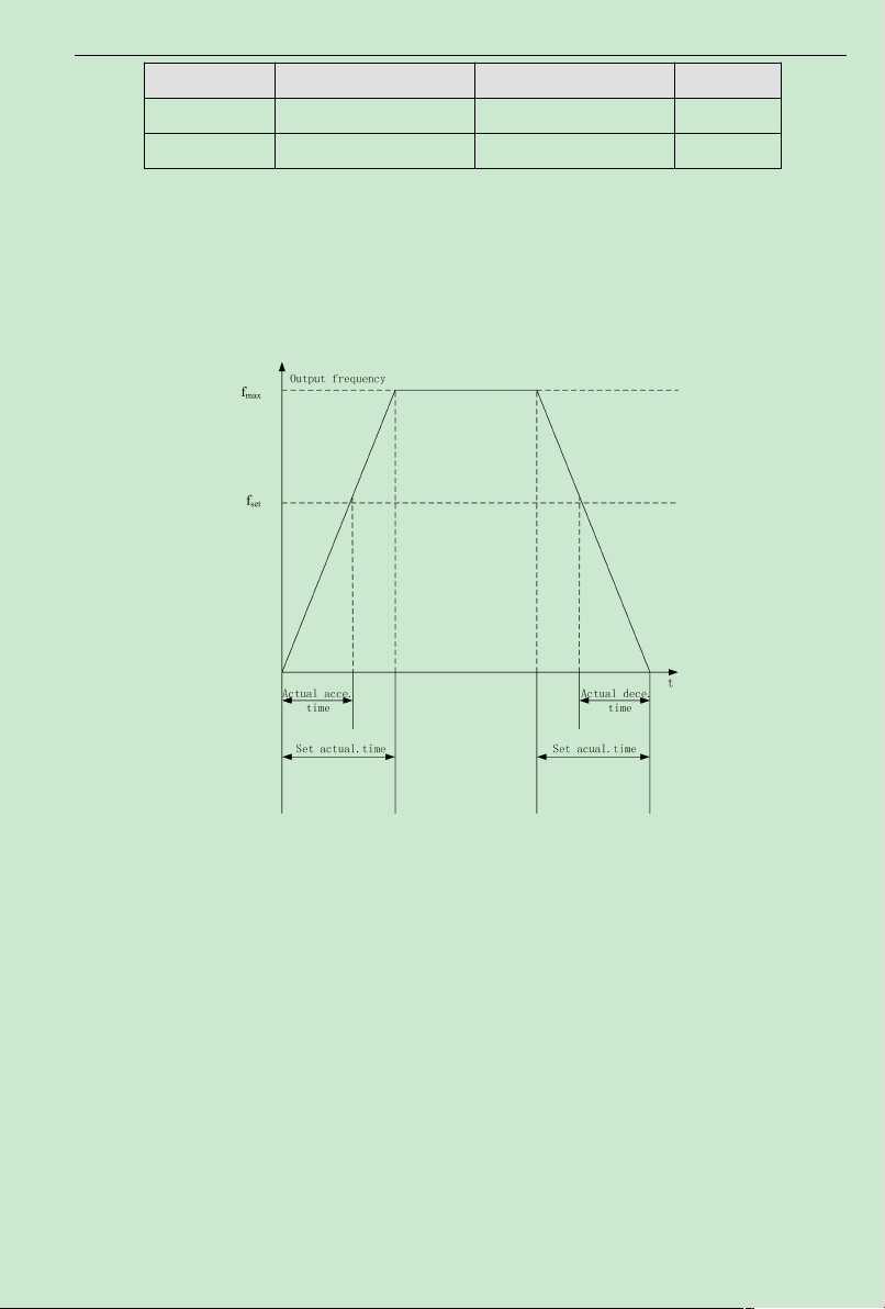
ACD320 user manual Parameter Description
Value
F0.08 ACCELtime 1 0.1~ 3600.0s 10.0s
F0.09 DECEL time 1 0.1~ 3600.0s 10.0s
Acceleration time means the time t1 required for inverter to accelerate to the maximum
output frequency (F0.04) from 0Hz.
Deceleration time is the time t2 required for inverter to decelerate to 0Hz fromthe
maximumoutput frequency (F0.04).
It is indicated by following figure
Fig 6-1 Acceleration and Deceleration time diagram
When the set frequency is equal to the maximum frequency, the actual
Acceleration/Deceleration time are equal to the set Acceleration/Deceleration time.
When the set frequency is less than the maximum frequency, the actual
Acceleration/Deceleration time are less than the set Acceleration/Deceleration time.
Actual Acceleration /Deceleration time = set Acceleration/Deceleration time (set
frequency/max.frequency)
ACD320 series inverter has 2 groups ofAcceleration/Deceleration time.
1st group: F0.08, F0.09;
2nd group: F4.00, F4.01;
The Acceleration /Deceleration time can be chosen through multifunction digital input
terminal (F2 Group).
- 58-
Page 64
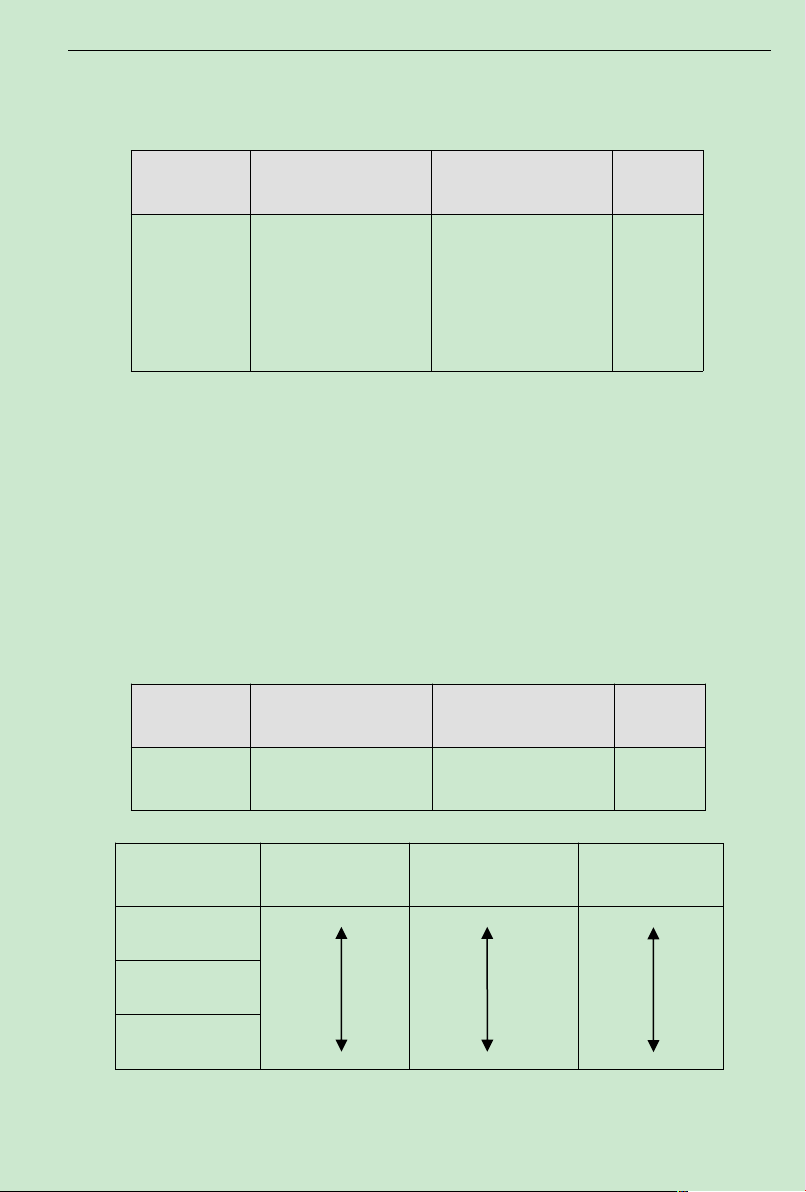
ACD320 user manual Parameter Description
small
large
large
large
small
small
The factory value of decelerating time is10.0s as to the inverter whose power is 5.5KW and
below, the value is 20.0S as to the inverter whose power is between7.5KW and 55KW, while the
value is 40.0S as to the inverter whose power is 75KW and above.
Function Code Name Setting Range
0: Operating at default
direction
1: Operating at reverse
direction
2: NO inverse operating
F0.10
Operation direction
selection
Default
Value
0
0: Operating at default direction.When the inverter is power connected, it operates at the
actual direction.
1: Operating at reverse direction. By means of changing the function code, the motor
rotating direction can be changed without changing any other parameters, which is equivalent to
change the motor rotating direction by exchanging any two of motor cables (U, V,W).
Note: After the parameters are initialized, the motor operating direction can be restored to be its original state. Be
caution to use it in the case that changing motor rotating direction is forbidden after the system commissioning is
completed.
2: Forbid inverse operating. Forbidding inverter inverse operation is suitable to specific
application that inverse operating is forbidden.
Function Code Name Setting Range
F0.11
Carrier frequency
setting
1.0~15.0kHz
Default
Value
Set by
model
Carrier
frequency
Electronmagnetic
noise
Cacophony,Leakage
current Heat
1KHz
10KHz
15KHz
Fig 6-2 Relationship between environment and Carrier frequency
Relationship betweenModel and Carrier frequency
- 59-
Heat radiation
Page 65

ACD320 user manual Parameter Description
Carrier
frequency
Model
G: 0.4k W~11K W
L: 0.75kW~15 KW
G: 15kW~55 K W
L: 18.5kW~75KW
G: 75kW~300KW
L: 90kW~315KW
Max carr ier
frequency (KHz)
15 1 6
8 1 3
8 1 1.5
Min carrier
frequency (KHz)
Factory setting
(KHz)
This function is mainly used to improve the motor operating noise and inverter interference
to external. The advantages of using high carrier frequency: relatively ideal current wave shape,
less harmonic current wave and low motor noise;
The disadvantages of using high carrier frequency: increased switch loss and inverter
temperature rises, affecting inverter output capacity so that it should be operated at derating
under high carrier frequency conditions; in the mean time, inverter leakage current and its
electromagnetic interference to external are increased.
The situations of using low carrier frequency is on the contrary. Too low carrier frequency
can cause operation unstable, torque reduced and even oscillation at low frequency.
When inverter is factory released, its carrier frequency has been set properly. Generally the
user does not need to modify this parameter.
Function Code Name Setting Range
0: Nooperation
1: Restore default value
2: Delete failure records
F0.12
Functional parameters
restoration
Default
Value
0
1: The inverter restores all parameters to their default value.
2: The inverter deletes recent failure records.
After the chosen function operation is completed, this function code is automatically
restored to 0.
Function Code Name Setting Range
Default
Value
- 60-
Page 66

ACD320 user manual Parameter Description
F0.13 AVR selection
0:Invalid
1:Valid all the time
2: Invalid during
deceleration
1
Start Mode
0:Directstart
1:DC braking first and
then start
Hold time of start
frequency
AVR means output voltage auto regulation.WhenAVR is invalid, output voltage will change
according to the change of input voltage (or DC bus voltage); WhenAVR is valid,output voltage
will remain constant within output capacity.
Note: When the motor is decelerating to stop, the inverter would decelerate to stop in a
shorter time and not to be over-voltage if automatic voltage stabilization AVR function is closed.
Function Code Name Setting Range
Default
Value
F0.14
0
0: Direct start: start from the starting frequency.
1: DC braking first and then start: First perform DC braking (pay attention to set up
parametersF0.17 and F0.18 ), and then start and run the motor at the start frequency. It is suitable
for small inertia loading which can cause reverse rotation at starting.
Function Code Name Setting Range
F0.15 Start frequency
F0.16
0.50~10.00Hz
0.0~50.0s
Default
Value
0.00Hz
0.0s
Setting proper starting frequency can increase the starting torque.Within the hold time of the
starting frequency (F0.16), the inverter output frequency is the starting frequency, and then,from
the starting frequency, running to the target frequency. If the target frequency (frequency
command) is less than the starting frequency, inverter does not operate and is at stand-by state.
The starting frequency value is not restricted by the lower limit frequency.
During FWD/REV switching, the starting frequency is inactive.
Function Code Name Setting Range
F0.17 Braking current before
starting
F0.18 Braking time before
starting
0.0~150.0%
0.0~50.0s
Default
Value
0.0%
0.0s
- 61-
Page 67

ACD320 user manual Parameter Description
When it is being started, the inverter first performs DC braking according to the set
prior-to-starting DC braking current, and after the set prior-to-starting DC braking time is passed
then begins to perform acceleration. If the set DC braking time is 0, DC braking is invalid.
The bigger the DC braking current, the greater the braking force. The prior-to-starting DC
braking current is the percentage of the rated inverter current.
Function Code Name Setting Range
F0.19 Stop Mode
0: DECELStop
1: FreerunStop
Default
Value
0
0: Deceleration stop
After the stop command is enabled, the inverter decreases the output frequency according to
the Decelerationmode and the definedAcceleration /Deceleration time, and the motor is stopped
when the frequency is 0.
1: Free-run stop
Once the stop command is valid, the inverter immediately ends the output. The loading is
freely stopped by its mechanical inertia.
Function Code Name Setting Range
F0.20
F0.21
F0.22 DC braking current 0.0~150.0% 0.0%
F0.23 DC braking time 0.0~50.0s 0.0s
Beginning Frequency of
braking
Waiting time of
braking
0.00~F0.04 0.00Hz
0.0~50.0s 0.0s
Default
Value
Beginning frequency of DC brake when stopping.During the Deceleration stop, when this
frequency is reached, the DC brake is started.
Waiting time of DC brake when stopping: Prior to the DC brake, the inverter blocks the
output, and after this delay time, the DC braking is started. It is used to prevent over-current fault
caused by DC braking at high speed.
DC brake current when stopping: indicates the applied DC brake energy. The bigger the
current, the stronger the DC brake energy should be.
DC brake time when stopping: the durative time that the DC brake energy is applied. If the
time is 0, DC brake is invalid, and the inverter stops the motor based on the set Deceleration
time.
- 62-
Page 68
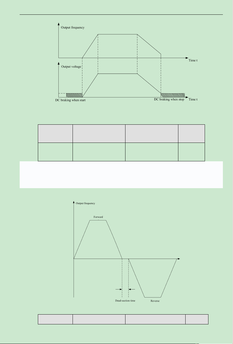
ACD320 user manual Parameter Description
Fig. 6-3 DC Brake Diagram
Function Code Name Setting Range
F0.24
Dead time between
forward and reverse
0.0~3600.0s 0.0s
Default
Value
In the transition process when the inverter runs transforming between forward and reverse,
the transition time that the output frequency is 0 is as follows:
Fig. 6-4 FWD/REV Dead Time Diagram
Function Code Name Setting Range Default
- 63-
Page 69

ACD320 user manual Parameter Description
F1.00
0: G model
1: L model
0-1 0
F1.01 Motor rated power 0.4~900.0kW
Set by
model
F1.02
Motor rated
frequency
0.01Hz~F0.04 50.00Hz
F1.03 Motor rated speed 0~36000rpm
Set by
model
F1.04 Motor rated voltage 0~460V
Set by
model
F1.05 Motor rated current 0.1~1000.0A
Set by
model
Value
0: Terminal command invalid
F0.25
Terminal command
protection when power on
when power on
0
1: Terminal command valid
when power on
If operating command channel is set to terminal control, system will detect terminal status
automatically during inverter power on.
0: Terminal command invalid when power on. Inverter will not run if it detect operating
command terminal is valid.When the operating command terminal is invalid and enable this
terminal again, inverter will run.
1: Terminal command valid when power on. Inverter will startup automatically after
initialization is finished if it detect operation command terminal is valid.
Note: Customer should be careful when you select this function, it may cause severe
consequence.
6.2 F1 Motor Parameters
Function Code Name Setting Range
Default
Value
Note: please set these codes according to motor nameplate parameters. The superior
performances of vector control require precise motor parameters.
ACD series inverter provides parameter self-learning function. Accurate parameter
self-learning comes from correct setting of motor nameplate parameters.
In order to ensure the control performances, please do the motor setting based on the
inverter standard adaptive motor. If the motor rated power has a too big difference to the
standard adaptive motor, the inverter control performances will be deteriorated distinctly.
Note: resetting of motor rated power (F1.01) can initialize motor parameter F1.02-F1.10.
- 64-
Page 70

ACD320 user manual Parameter Description
F1.06
Motor stator
resistance
0.001~65.535Ω
Set by
model
F1.07
Motor rotor
resistance
0.001~65.535Ω
Set by
mode
F1.08
Motor stator/rotor
inductance
0.1~6553.5mH
Set by
mode
F1.09
Mutual inductance of
motor stator/rotor
0.1~6553.5mH
Set by
mode
F1.10 No-load current 0.01~655.35A
Set by
mode
Function Code Name Setting Range
Default
Value
After the motor self-learning is normally ended, F1.06-F1.10 setting values are
automatically replaced. These parameters are the basis of high performance vector control and
have direct effect on the control performance.
Important: users DO NOT change this group parameters at will.
Function Code Name Setting Range
0:NOoperation
1: complete tuning
Self-learning
2: static tuning
Self-learning
F1.11
Self-learning of motor
parameters
Default
Value
0
Note:This function is invalid for ACD200Seriess.
0: NO operation, forbidding self-learning.
1: self-learning of parameters
Prior to parameters self-learning, the motor must be disconnected with its load-ensuring the
motor at no-load condition, and confirming the motor is at static state.
Prior to parameters self-learning, it is a must to correctly input the motor nameplate
parameters(F1.01~F1.05), otherwise what is self learned about motor parameters may be not
correct.
Prior to parameters self-learning, theAcceleration and Deceleration time (F0.08 and F0.09)
should be set properly based on the motor inertia, otherwise over current fault may happen
during motor parameters self-learning.
When the self-learning of motor parameters is started by setting F1.11 as 1 and then pushing
the button FUNC/DATA, LED displays -TUN- and flickering, then push the button RUN to
- 65-
Page 71

ACD320 user manual Parameter Description
F1.12
Speed loop proportional
gain1
0~100 30
F1.13 Speed loop integral time1 0.01~10.00s 0.50s
F1.14
Switching low
point frequency
0.00Hz~F1.1 7 5.00Hz
F1.15
Speed loop proportional
gain 2
0~100 25
F1.16
Speed loop integral
time 2
0.01~10.00s 1.00s
F1.17
Switching high
point frequency
F1.14~F0.04 10.00Hz
begin the procedure of the motor parameters self-learning. At this time, TUN-0 is displayed.
After the motor is started, TUN-1 is shown and RUN light is flickering.
When the self-learning of parameters is finished, -END- is displayed, and finally back to the
stop state interface.
When -TUN- is blinking, the process of parameters self-learning can exit by pushing the
button PRGM/RESET .
During the process of parameters self-learning, it can be stopped by pressing the button
STOP.
Please note, the start and stop of the parameters self-learning can only be done through
keypad. Once the parameter self-learning is finished, this function code automatically restores to
0.
Function Code Name Setting Range
Default
Value
Above parameters are valid only to vector control, but invalid toV/F control.When the
frequency is less than the switching frequency point 1 (F1.14), the speed loop PI parameters are
F1.12 and F1.13.When frequency is higher than the switching frequency point 2 (F1.17),the
speed loop PI parameters are F1.15 and F1.16. Between the switching points, PI parameter is
acquired according to the line type variation of the two group parameters, as shown in following
figure.
- 66-
Page 72
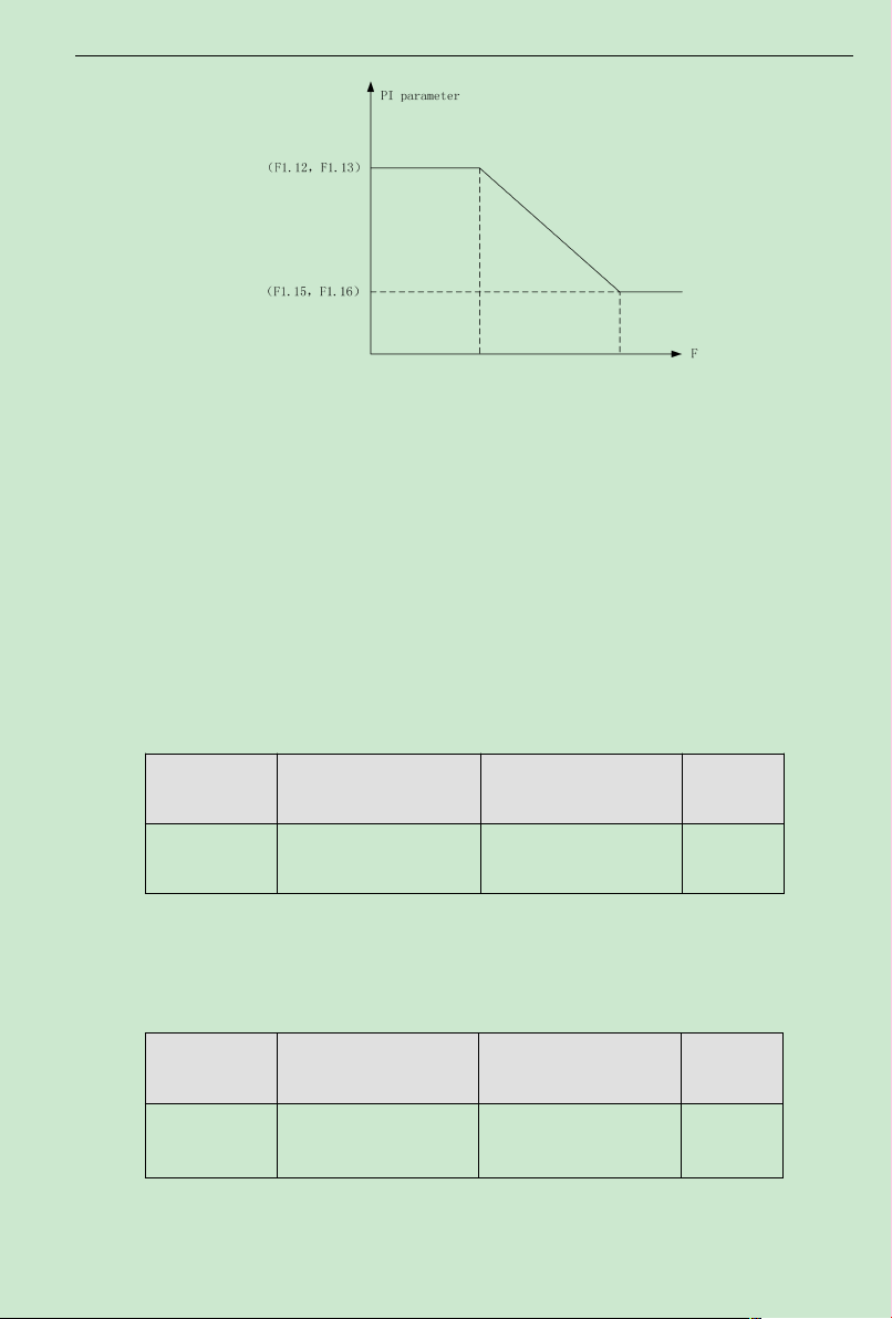
ACD320 user manual Parameter Description
Fig. 6-5 PI ParameterDiagram
By means of setting the proportion factor and integration time of the speed regulator, the
speed dynamic response of vector control can be regulated. Increasing the proportional gain,and
reducing the integration time, can equally quicken the dynamic response of speed loop,but either
the proportional gain being too much or the integration time being too short can easily cause
system oscillation and too big overshoot. The proportional gain being too small also can lead to
system steady state oscillation and possibility of speed steady-state error occurring.
Speed loop PI parameters have an intimate relationwith the inertia ofmotor system, and
therefore based on the default PI parameter the user needs to make adjustment for different
loading character in order to meet different requirement.
Function Code Name Setting Range
F1.18
VC slip
compensating factor
50%~200% 100%
Default
Value
The slip compensating factor is used to adjust the slip frequency of vector control and
improve the system speed control accuracy. Properly regulating this parameter can effectively
restrain the speed steady-state error.
Function Code Name Setting Range
F1.19
Upper torque l imit
setting
0.0 ~ 200.0%(inverter
rated current)
Default
Value
150.0%
The setting 100.0%is corresponding to the rated output current.
The function code below (F1.20~F1.24) are valid to V/F control ( F0.00 =1 ), but invalid to
- 67-
Page 73
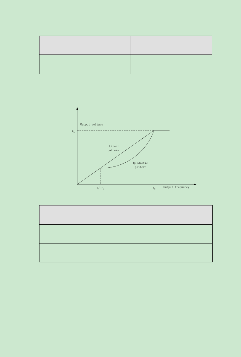
ACD320 user manual Parameter Description
vector control.
Function Code Name Setting Range
F1.20 V/F curve setting
0: LinearV/Fcurve
1: square torque V/F curve
Default
Value
0
0: LinearV/F curve. It is applicable to constant torque load.
1: 2.0 exponential V/F curve. It is applicable to variable torque load, such as blower,
pump etc.
Fig. 6-6 V/F curve
Function Code Name Setting Range
F1. 21 Torque boost
F1. 22 Torque boost cut-off
0.0%:(auto) 0.1 % ~ 30.0
%
0.0% ~ 50.0% (relative to
motor rated frequency)
Default
Value
0
20.0%
Torque Boost is mainly applied to less than cut-off frequency (F1.22). TheV/F curve after
boost is shown in following figure. Torque booth can improve the low frequency torque
performance ofV/F control.
Based on the load, a torque should be chosen properly. For heavy load, increase the torque
boost, but the torque boost should not be set too big, whichwill result in the motor operating at
overexcitation and that it could be overheated, and also the inverter output current is big,
reducing efficiency.
When the torque boost is set as 0.0%, the inverter is at automatic torque boost.
- 68-
Page 74
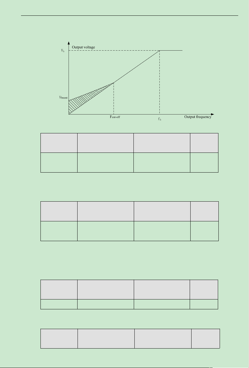
ACD320 user manual Parameter Description
Torque boost cut-off frequency: below this frequency, torque boost is valid, and above this
frequency setting, torque boost is invalid.
Fig. 6-7Manual torque boost diagram
Function Code Name Setting Range
F1. 23
V/F slip
compensation limit
0.0~200.0% 0
Default
Value
Setting this parameter can compensate the motor speed change produced because of
undertaking loading while on V/F control, to increase the rigidity of motor mechanical
performance. This value should be set as the motor rated slip frequency.
Function Code Name Setting Range
F1. 24
Energy Conservation
Selection
0: No Operation
1: Energy Conservation
Default
Value
0
When the motor is running in no-load or lower-load during,the inverter can output voltage
by adjust automatically current kf the load。
Note:This function is especially valid for variable torque load (such as fan and pump).
6.3 F2 Input and Output Terminal Function Parameters
Function Code Name Setting Range
F2.00 On-off signal filter times 1~10 5
It sets up MI1~MI6,AVI and ACI terminals sample filtering time. In big interference
situation, this parameter should be increased in order to preventmal operation.
Function Code Name Setting Range
Default
Value
Default
Value
- 69-
Page 75

ACD320 user manual Parameter Description
MI1 Terminal Function
Selection
MI2 Terminal Function
Selection
MI3 Terminal Function
Selection
MI4/FWD Terminal
Function Selection
MI5/REV Terminal
Function Selection
MI6 Terminal Function
Selection
Setting
value
Function Description
0 No Function
Even if there is a signal input, the inverter does not run.
Terminals which are not used can be set to be no function in order
to prevent malfunction
1 Forward
The inverter ’s forward or reverse running can be control by
external terminals.
2 Reverse
3
Three-wire operation
control
By means of this terminal the inverter s operation mode can be
defined to be three-wire control mode. For details, please refer to
the function code description of F2.07 three-wire control mode.
4 Forward Jogging At Jogging operation, the frequency and Jogging
Acceleration/Deceleration time can be found in detail descriptions
of F4.02,F4.03 and F4.04 function codes.
5 Reverse Jogging
6 Free-run stop
The inverter turns off output, and the motor stop process is not
controlled by the inverter. It is often applied when the inertia
loading is big and there is no requirement on stop time. This mode
has the same definition as F0.19 does.
7 Failure reset
This is external failure reset. It has the same function as STOP
button on the keyboard. Using this function can
performlong-distance failure reset.
8 External fault input When external fault signal is input, the inverter reports it and stops.
9
Frequency
up setting(UP)
When the frequency is set by external terminal, modify the
frequency up and down command.When the frequency
source is set as digital setting, the set frequency can be
regulated up and down.
Using terminal can clear UP/DOWNset frequency so that set
frequency can be restored the frequency setting given by frequency
10
Frequency
down setting
(DOWN)
11
Frequency up/down
setting clear
F2.01
F2.02
F2.03
F2.04
F2.05
F2.06
0~31 0
0~31 0
0~31 0
0~31 1
0~31 2
0~31 0
These parameters are used to set up the corresponding functions of digitalmultifunction
input terminals.
- 70-
Page 76
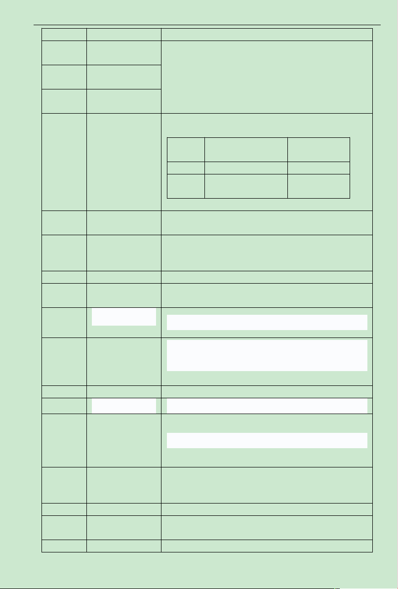
ACD320 user manual Parameter Description
command channel.
12
Multi-speed terminal
1
8 stages speed can be set up via these 3 terminals digital state
combination.
Note:multi-speed 1 is the low position, and multi-speed 3 is the
high position.
13
Multi-speed terminal
2
14
Multi-speed terminal
3
15
ACCE/DCCE time
selection terminal
2 kinds ofACCE/DCCE time can be chosen via these two terminals
digital state combination.
Terminal
ACC/DCC time
selection
Parameter
O F F ACCE time 0 F0.08、F0.09
N
ACCE time 1 F4.00、F4.01
16 PID control pause
PID is temporarily out of work, and the inverter keeps its current
frequency output
17 Traverse pause
The inverter pauses at its current output frequency.After this
function is cancelled, continue to start its traverse operation at its
current frequency.
18 Traverse reset The inverter is back to its center frequency output.
19
Acceleration/
Deceleration forbid
Ensure the inverter is not interfered by external signals ( excluding
stop command ), maintaining its current output frequency.
20
23
One driving two
circularly water
supply mode is
ineffective
21,22,24 Reserved
25
26
Simple PLC run
ineffective
27
Switch to the set of
ACI frequency.
No matter which value F0.03 is set, frequency setting channel is
ACI effective when terminal is closed, and F0.03 run command
channel recover after terminal isopened.
28 Jog key Jog run according to current status(forward or reverse)
29
Torque control
forbidden
The inverter switch the control mode from torque control to speed
comtrol.
30 Frequency When terminal is closed, the frequency value UP/DOWN has set is
External sleep signal
Simple PLC run reset To restore the PLC run to initial state.
Please refer to F7.28 for detailed description.
One driving two circularly water supply mode is ineffective, and it
is used in the case of manual operation.
PLC run pause.
- 71-
Page 77
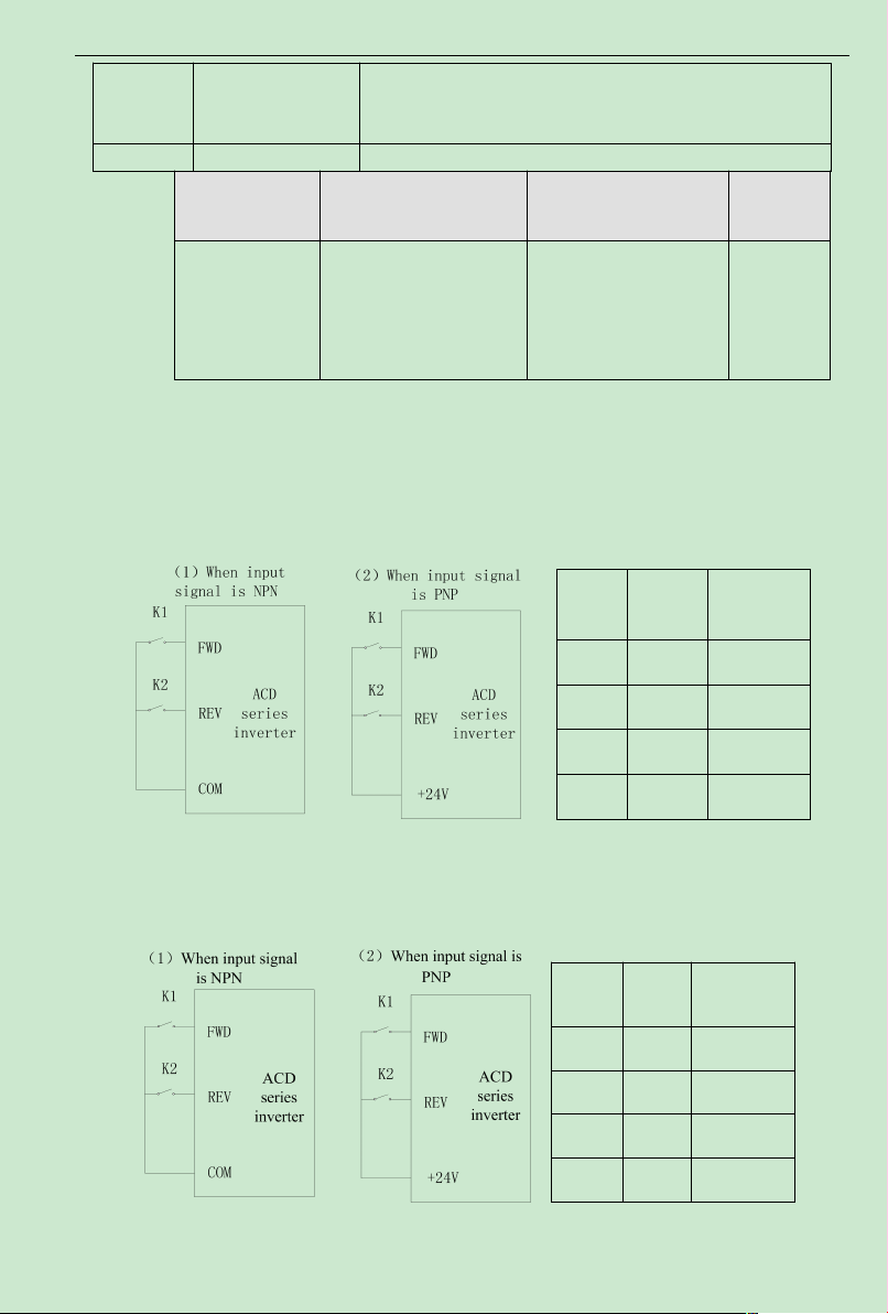
ACD320 user manual Parameter Description
increasing/decreasing
set clear temporarily
clear, and the given frequency will return to that the frequency
command channel has given, while it will to the frequency value
after the increasing/decreasing set.
31 Reserved
K1 K2
Operation
Command
OFF OFF STOP
ON OFF FWD
OFF ON REV
ON ON STOP
K1
K2
Operation
Command
OFF
OFF
STOP
ON
OFF
FWD
OFFONSTOP
ONONREV
Function Code Name Setting Range
0: two-wirecontrol 1
F2.07
Terminal cont rol
mode
1: two-wirecontrol2
2: three-wire control 1
3: three-wire control 2
Default
Value
0
This parameter defines four different control modes which controls the inverter operation
through external terminals.
0: Two-wire type control, integrate Enable with direction. This mode is the most often used
two-wire controlmode. The motor forward and reverse operations are determined by the defined
FWD and REV terminal command.
Fig. 6-8 Two-wire operation mode 1
1: Two-wire control, separateEnable fromdirection.When thismode is used, the defined
FWDis enable terminal. The direction is determined by the defined REVstate.
Fig. 6-9 Two-wire operation mode 2
- 72-
Page 78
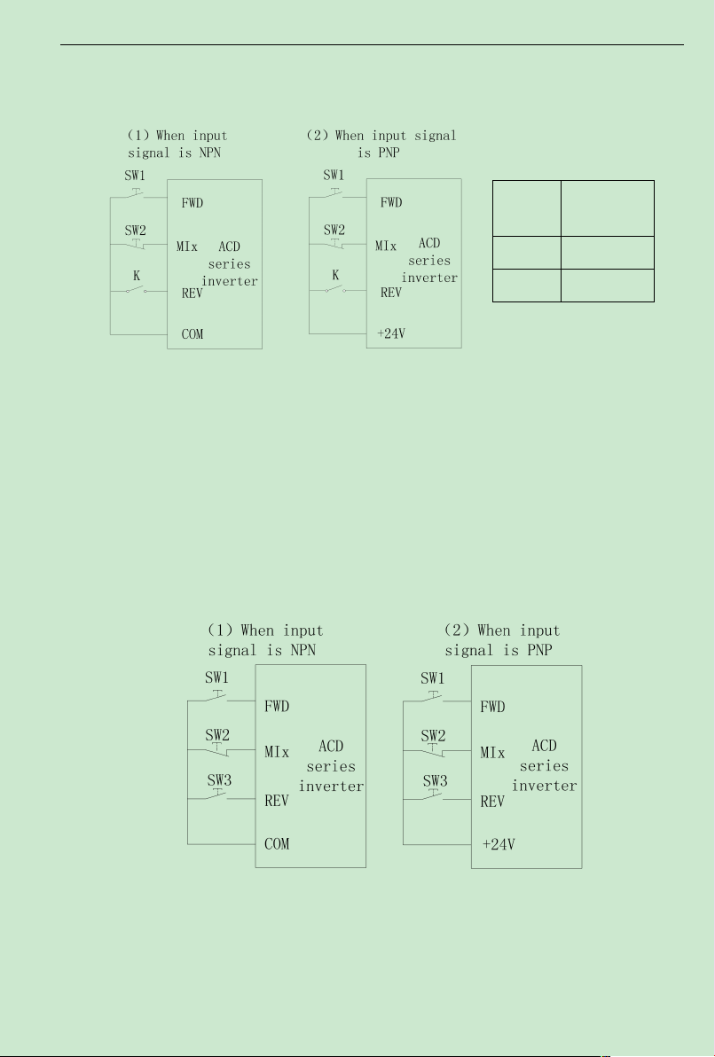
ACD320 user manual Parameter Description
K
Operation
Command
OFF FWD
ON REV
2: Three-wire control 1, integrate Enable with direction.At thismode, EN is the Enable
terminal with the direction controlled by the defined FWD. REV define the direction.
Fig. 6-10 Three-wire operation mode 1
K: FWD/REV switch SW1: RUN button SW2: STOP button
MIx is defining the corresponding terminal function as Function 3 “Three-wire operation
control ”.
3: Three-wire control, separate Enable from direction.At thismode EN is the Enable
terminal, SW1 or SW3 define operating command and control direction at the same time. Stop
command is defined by SW2.
SW1: FWD operating button SW2: STOP button K: REVoperating button
MIx is defining the corresponding terminal function as Function 3 “Three-wire operation
control ”.
Fig. 6-11 Three-wire operation mode 2
- 73-
Page 79

ACD320 user manual Parameter Description
AVI lower limit
AVI lower limit
corresponding setting
AVI upper limit
corresponding setting
AVI upper limit
corresponding setting
AVI input filtering time
Note: For two-wire operation mode, when FWD/REV terminal is enabled and the stop
command produced by other sources stops the equipment, the inverter does not start to operate
after the stop command disappears even if the control terminal FWD/REV is still valid. If the
inverter needs to operate, it is required to trigger FWD/REVagain.
Function Code Name Setting Range
UP/DOWN
F2.08
frequency increment
variable rate
0.01~50.00Hz/s 0.50Hz/s
Default
Value
Terminal UP/DOWN regulates the change rate of frequency setting.
Function Code Name Setting Range
F2.09
0.00V~10.00V 0.30V
Default
Value
F2.10
F2.11
F2.12
F2.13
-100.0%~100.0% 0.0%
0.00V~10.00V 9.70V
-100.0%~100.0% 100.0%
0.00s~10.00s 0.10s
Above function codes define the relationship between analog input voltage and the setting
value that analog input is corresponding to.When the analog input voltage exceeds the range of
the set maximum or minimum input, the beyond portion should be calculated with maximum
input or minimum input.
When analog input is amperage input, 0mA-20mAis corresponding to 0V-10V.
For different applications, the corresponding nominal value of analog setting 100.0%is
different. For details, please refer to each application description.
Following figures shows several settings. Note: AVI lower limit must be less or equal to
AVI upper limit.
- 74-
Page 80
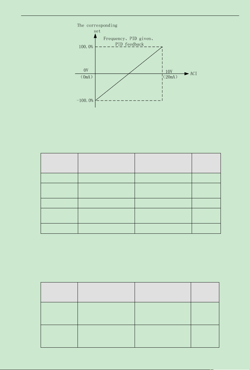
ACD320 user manual Parameter Description
ACI lower limit
ACI lower limit
corresponding setting
ACI upper limit
ACI upper limit
corresponding setting
ACI input filtering time
Relay RA/B/C output
selection
DO (Open circuit
collector )output
selection
Fig. 6-12Relationship between analog input and setting value
AVI input filtering time determines analog input sensitiveness. Increasing this parameter, in
order to prevent malfunction caused by interference to the analog, can strengthen the
anti-interference ability, but reduce the analog input sensitiveness.
Function Code Name Setting Range
F2.14
0.00V~10.00V 0.30V
Default
Value
F2.15
F2.16
F2.17
F2.18
ACI function settings are similar toVI setting method.
ACD320 Series inverter provides 2 paths of analog input port.
ACD320 Series inverter standard unit has twomultifunction digital output terminal, one (or
two) multifunction relay output terminals and one analog output terminal.
Function Code Name Setting Range
F2.19
F2.20
- 75-
-100.0%~100.0% 0.0%
0.00V~10.00V 9.70V
-100.0%~100.0% 100.0%
0.00s~10.00s 0.10s
Default
Value
0~24 3
0~24 3
Page 81

ACD320 user manual Parameter Description
Relay TA/B/C output
selection
F2.21
0~24 3
Open collector output functions are indicated as following table:
Setting
value
0 Zero Output Output terminal has no function
1 Frequency reached
2 FDT reached
3 Fault output Once inverter fault happens, output ON signal
4
5
6 Null speed operation
7
8
9~12 Reserved Reserved
13
14
15 Sleep status indication Output ON signal and display “EoPP” in sleep status.
16
17
18 Running
19~20 Reserved Reserved
Function Descript ion
Please refer to the detail description of function code
F4.15
Please refer to the detail description of function code
F4.13,F4.14
Inverter is running
forward
Inverter is running
revers
Upper limit frequency
reached
Lower limit frequency
reached
High pressure arrives
detect value
Low pressure arrives
detect value
Lack of water alarm
indication.
Run at nonzero speed Output ON signal when output frequency is larger than
ON signal Indicates the inverter is running forward with
output frequency
ON signal Indicates the inverter is running reverse with
output frequency
When the inverter output frequency is less than the
starting frequency, output ON signal
When the operating frequency reaches the upper
frequency limit, output ON signal.
When the operating frequency reaches the lower
frequency limit, output ON signal.
When the pressure is higher than F7.12 detection value,
ON signal output.
When the pressure is lower than F7.13 detection value,
ON signal output.
Output ON signal and display “U-26” when lack of water.
minimum output frequency.
Output ON signal when the inverter has output or
operation command input.
- 76-
Page 82
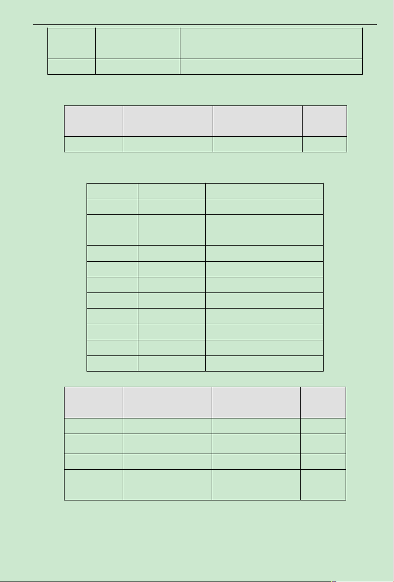
ACD320 user manual Parameter Description
AO1 Lower limit
Lower limit corresponding
AO1 output
AO1 Upper limit
21
22~24 Reserved Reserved
Function Code Name Setting Range
Simple PLC run for a
cycle
F2.22 AO1 output selection 0~10 0
After simple PLC run for a cycle, output impulse signal of
500ms.
Default
Value
The standard analog output is 0-20mA(or 0-10V). Current or voltage output can be selected
by Jumper S2. Its corresponding value range is shown as following table:
Setting Value Function Range
0 Setting frequency 0-maximum output frequency
1
2 Output current 0-double rated inverter current
3 Output voltage 0-1.5 times rated inverter voltage
4 Motor speed 0-double rated motor speed
5 Output power 0-double rated power
6 Output torque 0-double rated motor current
7 Analog AVI input 0~ 10V/0~20mA
8 Analog ACI input 0~ 10V/0~20mA
9~10 Reserved Reserved
Operating
frequency
0-maximum output frequency
Function Code Name Setting Range
F2.23
F2.24
F2.25
F2.26
Upper limit corresponding
AO1 output 0.00V~10.00V 10.00V
0.0%~100.0% 0.0%
0.00V~10.00V 0.00V
0.0%~100.0% 100.0%
Default
Value
Above function codes define the relationship between output value and analog output
corresponding output value.When the output value exceeds the maximum output or the minimum
output range, the beyond portion should be calculated with maximum output or minimum output.
- 77-
Page 83
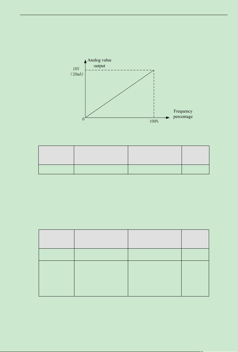
ACD320 user manual Parameter Description
Function Code Name Setting Range
F3.01
Application of
macroinstruction
0~65535
F3.02
Selection of M key
function
0:JOG running
1: Switch between
running forward and
reverse
2: Clear the set of
UP/DOWN
When analog output is current output, 1mAis equivalent to 0.5V For different applications,
the analog output corresponding to 100%output value is different. For details, please refer to the
instruction of each application.
Following figures explain several setting circumstances:
Figure 6-13 The coincidence relationship between assigned value and analog output
6.4 F3 Human Machine Interface Parameters
Function Code Name Setting Range
F3.00 User password 0~65535 0
User password is applied to prevent non-authorized person to look and modify
parameter.Input a nonzero five digit number as password, then press ENTER/DATA to confirm,
if there is no button operation in one minute, password function becomes effective.
After password becomes effective, customer can not access parameter list if password input
is incorrect. Please remember the password. If it is not necessary to set password, just set 00000
to clear password.
Default
Value
Default
Value
0
F3.01=1233 the application macro of Offset printing machine, F3.01=1235 the application
macro of engrving machine F3.01=1237 the application macro of constant pressure water
supply.
The only need is to set F3.01 to corresponding macroinstruction, then restore F0.12=1 to
- 78-
Page 84

ACD320 user manual Parameter Description
STOP function option
0: Keypad control valid
1: Keypad and terminal
control valid
2: Keypad and
communication
control valid
3: All controlmodes valid
BIT0: Running frequency
BIT1: Setting frequency
BIT2: Output current
BIT3: Output voltage
BIT4: Running speed
BIT5: Output power
BIT6: Output torque
BIT7: DC bus voltage
factory value, and fine control relevant parameter.
Function Code Name Setting Range
F3.03
This function code is to define the STOPstop function validity options.
Function Code Name Setting Range
F3.04 Reserved 0
Function Code Name Setting Range
F3.05
F3.06
F3.07
operation status display
parameter option
Stop status display
parameter option
operation status display p
eferential option
0-65535 1183
0-65535 207
0~15(0:invalid) 0
Operation status display:
Displayed Message Code
1 1
2 ******
4 2
8 3
16 4
32 5
64 6
128 7
F3.07
code
Default
Value
0
Default
Value
Default
Value
- 79-
Page 85
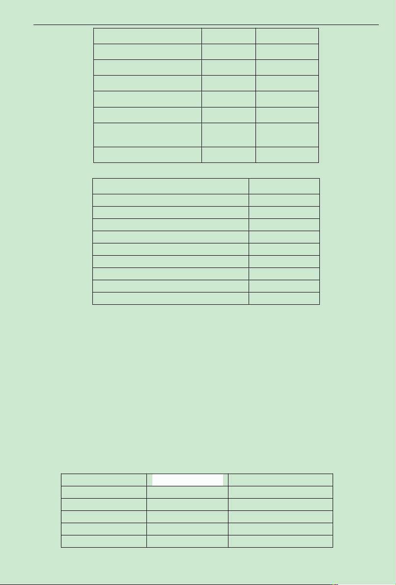
ACD320 user manual Parameter Description
BIT8: PID setpoint
BIT9: PID feedback
BIT10: Input terminal status
BIT11: Output terminal status
BIT12: AVI value
BIT13: ACI value
BIT14: Current segment of
multi-speed control
BIT15:Torque setting value 32768
BIT0:Setting frequency 1
BIT1:DC bus voltage 2
BIT2:Input terminal status 4
BIT3:Output terminal status 8
BIT4:PID setpoint 16
BIT5:PID feedback 32
BIT6:AVI value 64
BIT7:ACI value 128
BIT8:Current segment of multi-speed control 256
Input terminal Effective Ineffective
MI1 1 0
MI2 2 0
MI3 4 0
MI4 8 0
MI5 16 0
256 8
512 9
1024 10
2048 11
4096 12
8192 13
16384 14
15
Stop status display:
Displayed Message Code
Option: setting parameter=the sum total of display code for example:
require to display at operation status:Output current,Running speed,Output power
4+16+32=52, then setting F3.05to 52 , its corresponding parameter can be viewed at operation
through pressing button "DATA".
This I/O terminal status is displayed in decimal system,S1 (MO1) corresponding to the
lowest digit.
For instance, input status displays 3 is indicting that terminal S1 and S2 are closed and
others are open.
For details, please see F3.17 and F3.18 description.
Input terminal state display with 10 hexadecimal, as following table:
- 80-
Page 86

ACD320 user manual Parameter Description
MI6 32 0
Output terminal Effective Ineffective
TA/B/C 1 0
RA/B/C 2 0
DO 4 0
The fault before previous
fault type
Previous fault type
For example:If input state displays 3, it means terminal MI1, MI2 is effective, and the other
terminals are ineffective .
Output terminal state display with 10 hexadecimal, as following table:
If output state displays 3, it means that terminalTA/TB/TC、RA/RB/RC are effective, and
DO terminal is ineffective .
The display of operating status of F3.07 selected preferentially.
0:The displaying content in operating state is selected by SHIFT key of the keyboard.
1--15: Correspond to F3.05 displaying contents.
In run status, switch to the displaying content that the parameter selects with 10 seconds
delay when there is no SHIFT key operation.
Automatically switch to the displaying content that the parameter selects when switching
from stop status to run status.
Function Code Name Setting Range
F3.08 IGBT module temperature 0~100.0℃
F3.09 Software version
F3.10
Accumulative operating
time
0~65535h 0
Default
Value
Actual
value
Actual
value
These functions only can be viewed but can not be modified.
IGBTmodule temperature: indicates the temperature of the inverter IGBTmodule.
Over-temperature protection value of different invertermay be different.
Software version: software version number.
Inverter accumulative operating time: displays current inverter accumulative operation time.
Function Code Name Setting Range
F3.11
0~29
Default
Value
F3.12
0~29
- 81-
Page 87

ACD320 user manual Parameter Description
Current fault type
F3.13
0~29
Record three recent fault types: 0 is no fault; 1~22 is 22 different kinds of fault. For
details,please see fault analysis.
Function Code Name Setting Range
F3.14 Operat ing frequency at
current fault
F3.15 Output amperage at
current fault
F3.16 Bus voltage at current
fault
Function Code Name Setting Range
F3.17 Reserved
F3.18 Reserved
The output frequency
when current fault
happens
The output amperage
when current fault
happens
The bus voltage when
current fault happens
Default
Value
0.00Hz
0.0A
0.0V
Default
Value
6.5 F4Application Function Parameters
Function Code Name Setting Range
F4.00 ACCELTime 2 0.1~3600.0s 10.0s
F4.01 DECEL Time 2 0.1~3600.0s 10.0s
Acceleration/Deceleration time can be chosen to be F0.08, F0.09 or above three time
settings. Their meanings are all the same; please refer to F0.08 and F0.09 related description.
TheAcceleration/Deceleration time 0-1 at inverter operation can be chosen through different
combination of multifunction digital input terminals.
Function Code Name Setting Range
F4.02 Frequency of JOG running 0.00 ~ F0.04(maximum
frequency)
F4.03 The acceleration time of
JOG running
0.1~3600.0s 10.0s
- 82-
Default
Value
Default
Value
5.00Hz
Page 88
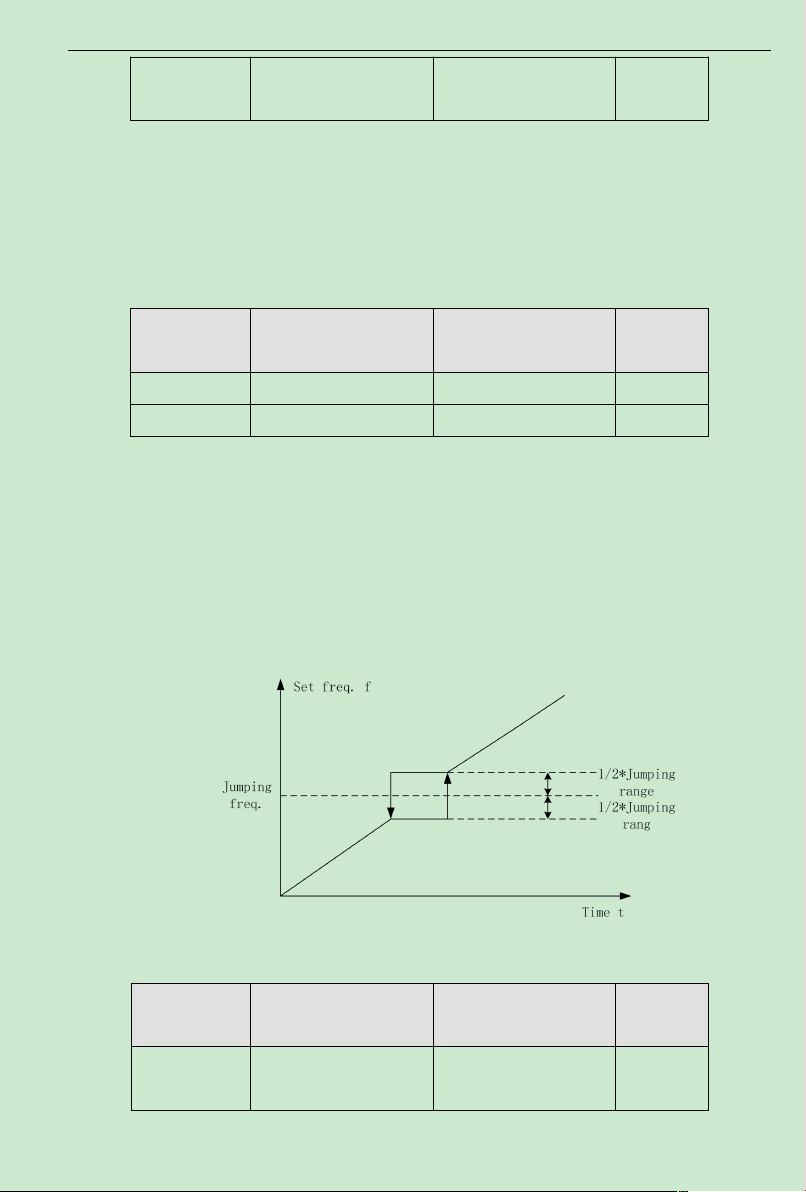
ACD320 user manual Parameter Description
0.0~100.0%(relative to
set frequency)
F4.04 The deceleration time of
JOG running
0.1~3600.0s 10.0s
It is to define the inverter set frequency and Acceleration/Deceleration time at Jog operation.
Jog operation is performed by direct start mode and deceleration stop mode.
The Acceleration time of JOG running is the time required for inverter to accelerate from
0Hz to the maximum output frequency (F0.04).
The Deceleration time of JOG runing is the time required for inverter to decelerate from the
maximum output frequency (F0.04) to 0Hz.
Function Code Name Setting Range
F4.05 Skip frequency 0.00~F0.04 0.00Hz
F4.06 Skip frequency range 0.00~F0.04 0.00Hz
Default
Value
When the set frequency is within the skip frequency range, the actual operating frequency
will be operated near the boundary of skip frequency range.
By means of setting skip frequency, the inverter can keep away from the mechanical
resonance point of the load.
This inverter has one skip frequency point available. If these two skip frequencies are both
set to 0, this function will be inactive.
Function Code Name Setting Range
Fig. 6-14 Skip frequency schematic diagram
F4.07 Traverse frequency range
- 83-
Default
Value
0.0%
Page 89
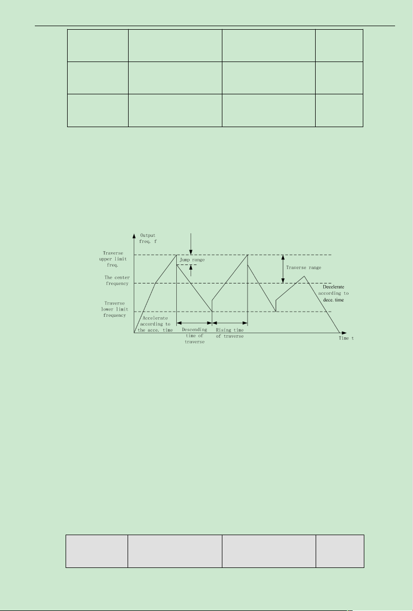
ACD320 user manual Parameter Description
0.0~50.0%(relative to
traverse frequency range)
F4.08 Kick frequency range
F4.09 Traverse frequency rising
time
F4.10 Traverse frequency
descending time
0.1~3600.0s
0.1~3600.0s
0.0%
5.0s
5.0s
Traverse frequency function is suitable to industries such as textile, fiber and so on, and to
applications which require traversing andwinding functions.
Traverse frequency function means that the inverter output frequency is traversing up and
down around the set frequency. The operating frequency locuswith time axis is shown as
following diagram, in which the amplitude of traverse is set by F4.07.When F4.07 is set to be 0,
i.e. traverse range is 0, the traverse frequency function will be inactive.
Fig. 6-15 Traverse Frequency Operation Diagram
Traverse frequency range: traverse operation frequency limits by upper and lower limit
frequency.
Traverse range relative to the center frequency: amplitude of traverseAW= CF×AWrange
F4.07
Kick frequency = amplitude of traverseAW×Kick Frequency Range F4.08. I.e. the kick
frequency is the value relative to amplitude of traverse at traverse-frequency operation.
Traverse frequency rising time: the time required to rise from the lowest traverse frequency
to the highest traverse frequency.
Traverse frequency fall time: the time required to fall from the highest traverse frequency to
the lowest traverse frequency.
Function Code Name Setting Range
- 84-
Default
Value
Page 90
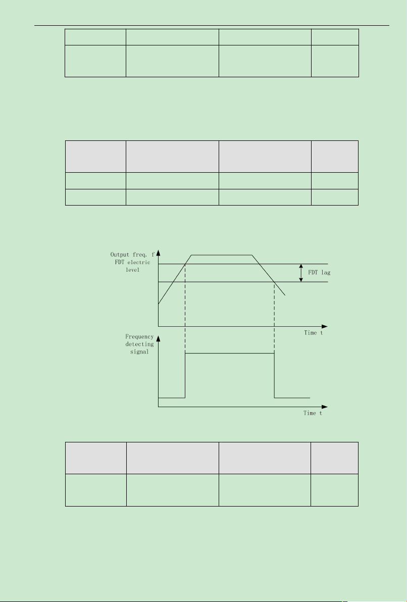
ACD320 user manual Parameter Description
F4.11 Fault auto-reset times 0~3 0
F4.12
Interval time setting of
automatic resetting fault
0.1~100.0s 1.0s
Fault auto-reset times: used to set the auto-reset times when inverter chooses fault auto-reset.
If this value is exceeded, inverterwill wait for trouble shooting.
Interval time setting of fault auto-reset: chose the interval time between fault occurring and
automatic resetting actuated.
Function Code Name Setting Range
F4.13 FDT level detection value 0.00~ F0.04 50.00Hz
F4.14 FDT delay detection value 0.0~100.0%(FDTlevel) 5.0%
Default
Value
Set output frequency detection value and the delay value of output action dismissed, as
shown by following figure:
Fig.6-16 FDT LevelDiagram
Function Code Name Setting Range
F4.15 Frequency reaching
detection range
0.0~100.0%(maximum
frequency)
Default
Value
0.0%
When the inverter output frequency reaches the set frequency value, this function can
regulate its detect ion range value, as shown by following figure:
- 85-
Page 91
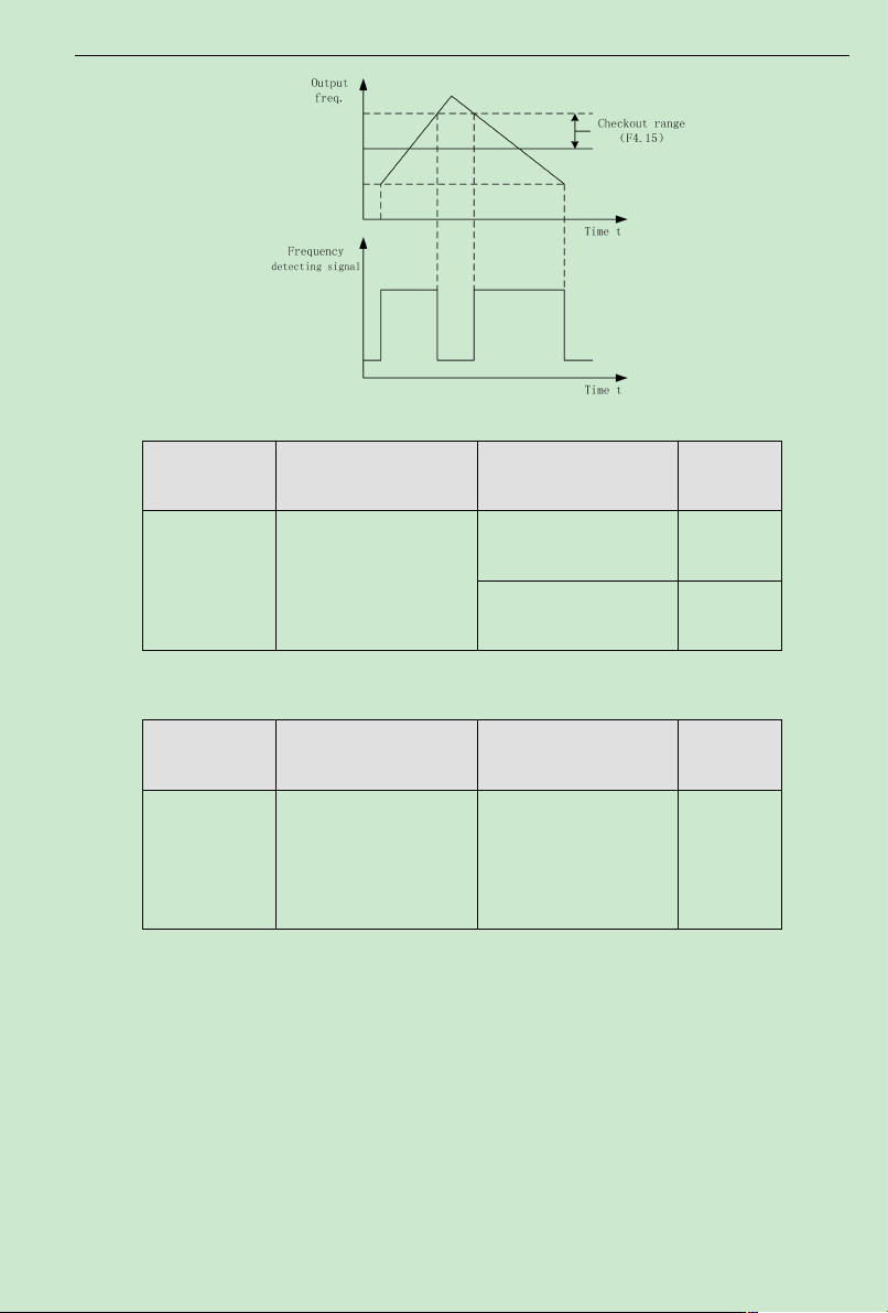
ACD320 user manual Parameter Description
Fig.6-17 Frequency Reaching Detection Range Diagram
Function Code Name Setting Range
115.0~140.0% ( standard
F4.16
Brake Threshold Value
Voltage
DC bus voltage) 380V
115.0 ~ 140.0%( standard
DC bus voltage) 220V
Default
Value
130.0%
120.0%
This function is to set up the initiative bus voltage of dynamic braking, and properly
regulating this value can result in an effective brake to the load.
Function Code Name Setting Range
0.1~999.9%
F4.17 Speed display ratio
Speed=120 × running
frequency × F4.17/pole
number
Default
Value
100.0%
Speed=120×running frequency ×F4.17/pole number
This function is used to calibrate speed display error, it has no impact on actual speed.
PID control is one method normally used to process control, holding the control value to the
target value by the negative feedback systemwhich regulates the inverter output frequency by
means of proportion, integration and differential operations on the difference between the control
value feedback signal and the target value signal. It is applicable to the process controls such as
flow control, pressure control and temperature control and so on. The control functional block
diagramis shown as follows:
- 86-
Page 92
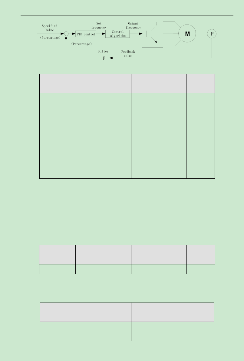
ACD320 user manual Parameter Description
Fig.6-18 Process PID Functional BlockDiagram
Function Code Name Setting Range
0: Given by Keyboard
(F4.19)
1: Given by Analog
Channel AVI
2: Given by Analog
Channel ACI
3: GivenbyRemote
Communication
4: Multi-seg setpoint
F4.18
PID setpoint Sources
Option
Default
Value
0
When frequency source is chosen to be PID, i.e. F0.03 is chosen to be 5, these group
functions are active.
This parameter is to determine the assignment channel of the process PIDtarget value.
The set target value of process PID is a relative value, and the set 100%is corresponding to
the 100% feedback signal of the system being controlled.
The system always performs the calculation according to relative value (0-100%)
Note: If multistage input, it can be accomplished by means of setting F4 group parameters.
Function Code Name Setting Range
F4.19 PresetPID setpoint 0.0%~100.0% 0.0%
Default
Value
When F4.08=0 is chosen, i.e. the target source is the keyboard, it is required to set this
parameter.
The reference value of this parameter is the system feedback value.
Function Code Name Setting Range
F4.20
PID Feedback Sources
Option
0: AVI Feedback
1: ACI Feedback
Default
Value
0
- 87-
Page 93

ACD320 user manual Parameter Description
2: A VI+ACI Feedback
3: Communication
feedback
4: AVI-ACI Feedback
The PID feedback channel is chosen by this parameter.
Important: The assignment channel and feedback channel can not be in coincidence,
otherwise PID is unable to control effectively.
Function Code Name Setting Range
F4.21
PID Output Characteristics
Option
0: positive
1: negative
Default
Value
0
PID output is positive characteristic:when the feedback signal is bigger than the PID given
signal, it is required for the inverter output frequency to decrease to counterbalance the PID, for
instance, the winding tension PID control.
PID output is negative characteristic:when the feedback signal is bigger than the PID giver
signal, it is required for the inverter output frequency to increase to counterbalance the PID,for
instance, the unreeling tension PIDcontrol.
Function Code Name Setting Range
F4.22 Proportional gain (Kp) 0.00~100.00 1.00
F4.23 Integral time (Ti) 0.01~10.00s 0.10s
F4.24 Differential time (Td) 0.00~10.00s 0.00s
Default
Value
Proportional gain (Kp): determines the adjusting strength of PIDadjustor. The bigger the P,
the bigger the adjusting strength is. This parameter being 100 means that when the difference
between the PID feedback value and the assigned value is 100%, the adjusting range of PID
adjustor to the output frequency command is the maximum frequency (ignore integral action and
derivative action).
Integrating time (Ti): determines the speed at which PIDadjustor performs integral
regulation to the discrepancy between the PID feedback value and the assigned value. The Ti is
indicating the period of time that integral controller (ignore proportional action and derivative
action), when the discrepancy between the PID feedback value and the assigned value is 100%,
continuously regulates to make the regulating amount to reach the maximumfrequency (F0.047).
The shorter the integrating time, the stronger the adjusting strength is.
Differential time (Td): determines the controlling strength at which PID adjustor performs
- 88-
Page 94

ACD320 user manual Parameter Description
adjustment to the variance ratio of discrepancy between the PIDfeedback value and the assigned
value. TheTd is indicating the period of time within which if the feedback value is changed
100%, the regulating amount of integral controller is the maximum frequency (F0.04) (ignore
proportional action and integral action). The longer the Td, the bigger the controlling strength
is.PID is the most popularly used controlmode in process control, with each part playing different
role. Following simply introduces the operational principle and the controlling method:
Proportion control (P): when there is discrepancy between feedback and the
assignment,output the regulating amount in proportion to the discrepancy. If the discrepancy is
constant,the regulating amount keeps constant. Proportion control can response quickly to the
feedback variation, but only using proportion control is unable to perform noncorresponding
control. The bigger the proportional gain, the faster the system regulating speed, but being too
bigmay cause oscillation. The control method is first to set a long integrating time and a zero
differential time, and then run the system only by using proportion control. Change the assigned
value, and watch the stable discrepancy (steady-state error) of feedback signal and assigned value.
If the steady-state error is at the varying direction of assigned value (for instance, increase the
assigned value, the feedback value after the system is steady is always less than the assigned
value), continue to increase the proportional gain, otherwise decrease it.Repeat the above until
the steady-state error is relatively small (it is very difficult to do no steady-state error).
Integral time (I): when there is a discrepancy between the feedback and
assignment,continuously accumulate the output regulation amount. If the discrepancy still exists,
continue to increase the regulation amount until there is no discrepancy. Integral controller can
effectively eliminate the steady-state error. Integral controller being too strong can cause
repeated overshooting, systemunstable and up till oscillating. The characteristic of oscillation
caused by too strong integral action is that the feedback signal is swinging up and down around
the assigned value, and the amplitude of swing increases gradually till the oscillation happens.
Normally the integral time is adjusted from big to small, gradually regulate the integral time, and
watch the effect, until the systemstable speed meets requirements.
Differential time (D): when the discrepancy between feedback and assignment varies,output
a regulation amount in proportion to the variance ratio of discrepancy. The regulation amount is
related to the direction and magnitude of discrepancy variation, but irrelevant to the direction and
value of the discrepancy itself. The differential control action is to perform the control according
to the varying trendwhen the feedback signal variation happens, and thereby to restrain the
feedback signal variation. It should be caution to use differential controller as the differential
control have a trend to magnify the system interference, especially the high varying frequency
- 89-
Page 95
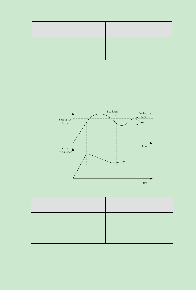
ACD320 user manual Parameter Description
interference.
Function Code Name Setting Range
F4.25 Sampling cycle time (T) 0.01~100.00s 0.10s
F4.26
PID control discrepancy
limit
0.0~100.0% 0.0%
Default
Value
Sampling time (T): is the time to sample the feedback value. In each sampling period the
controller runs one time. The longer the sampling time, the slower the responding.
PID control discrepancy limit: the allowable maximum discrepancy of PIDsystem output
value relative to the closed-loop assigned value.As shown in following diagram,within the
discrepancy limit, PID controller stops adjustment. Properly setting this function code can
improve the accuracy and stability of PIDsystem.
Fig. 6-19 Coincidence relation of discrepancy limit and output frequency
Function Code Name Setting Range
F4.27 Feedback disconnection
detecting value
F4.28 Feedback disconnection
detecting time
0.0~100.0% 0.0%
0.0~3600.0s 1.0s
Default
Value
Feedback disconnected detecting value: this detecting value is relative to the full range
(100%).
The system detects the PID feedback value all the time.When the feedback value is less or
equal to the feedback disconnected detecting value, the system starts to time the detection.When
- 90-
Page 96
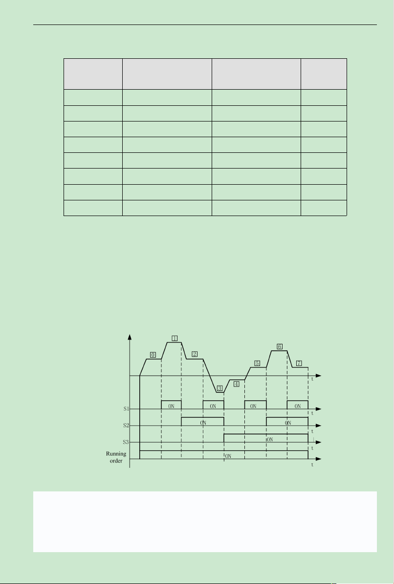
ACD320 user manual Parameter Description
the detecting time exceeds the feedback disconnected detecting time, the system will send an
alert of feedback disconnecting failure . (U-25)
Function Code Name Setting Range
F4.29 Multi-Speed 0 -100.0~100.0% 0.0%
F4.30 Multi-Speed 1 -100.0~100.0% 0.0%
F4.31 Multi-Speed 2 -100.0~100.0% 0.0%
F4.32 Multi-Speed 3 -100.0~100.0% 0.0%
F4.33 Multi-Speed 4 -100.0~100.0% 0.0%
F4.34 Multi-Speed 5 -100.0~100.0% 0.0%
F4.35 Multi-Speed 5 -100.0~100.0% 0.0%
F4.36 Multi-Speed 7 -100.0~100.0% 0.0%
Default
Value
Note: The multi-speed symbol defines the operation direction. If it is negative, the operation
direction is reverse. Frequency setting 100.0% is corresponding to maximum frequency(F0.04).
When MI1=MI2=MI3=OFF,the input mode is chosen by F0.03. When terminals MI1
、
MI2、MI3 are not all OFF and multi-step speed run, priority of multi-step speed is higher than the
input of keyboard,simulation and communication frequency, through the combined code, 8-step
speed can be chosen at most.
Fig.6-20multi-speed logic Diagram
The selection of stop channel starting is also determined by function code F0.01 when
inverter is running at multi- speed, and the multi- speed control process is shown in Fig.6-20.
The relation between MI1、MI2、MI3 terminal and multi-speed section is shown in the following
table.
- 91-
Page 97

ACD320 user manual Parameter Description
Relationship betweenmulti-speed and MI1、MI2、MI3 terminals:
MI1 MI2 MI3
OFF OFF OFF Multi-Speed 0
ON OFF OFF Multi-Speed 1
OFF ON OFF Multi-Speed 2
ON ON OFF Multi-Speed 3
OFF OFF ON Multi-Speed 4
ON OFF ON Multi-Speed 5
OFF ON ON Multi-Speed 6
ON ON ON Multi-Speed 7
Current segment of
multi-speed control
6.6 F5 Protection Parameters
Function Code Name Setting Range
0: Noprotection
F5.00
Motor Overload
Protection Option
1: normal motor
2: Variable
Frequencymotor
0: no protection. There is nomotor overloading protection characteristic (caution to use),and
thereby the inverter has no protection to the overloaded motor.
1: normalmotor (with low speed compensation).As generalmotor has a poor heat emission at
low speed, the relevant electronic thermal protection should be regulated properly.The low speed
compensation characteristic herementioned is to switch down the overloading protection
threshold for themotor with an operation frequency lower than 30 Hz.
2:Variable frequencymotor (without lowspeed compensation).As the heat emission of
special variable frequency motor is not affected by speed, it is not required to regulate the
protection value for lowspeed operation.
Function Code Name Setting Range
F5.01
Motor Overload
Protection Current
20.0% ~ 120.0%(motor
rated current)
Default
Value
1
Default
Value
100.0%
- 92-
Page 98
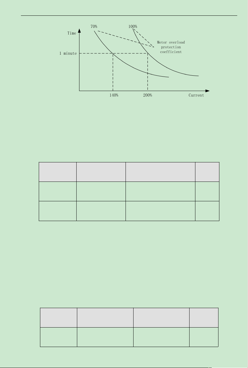
ACD320 user manual Parameter Description
Fig.6-21 Motor Overload Protection Current
The value can be determined by following equation:
Motor overload protection current = (maximum current/rated current)×100%
It is mainly applied to the cases that big inverter drives small motor, requiring to correctly
set up this function to protect the motor.
Function Code Name Setting Range
F5.02
F5.03
Power-down
Frequency Drop Point
Instant power-down
Frequency drop rate
70.0~110.0%(standard bus
voltage)
0.00Hz~F0.04 0.00Hz
Default
Value
80.0%
If the instant power-down drop rate is set to be 0, the instant power-down restart function is
invalid.
Instant power-down frequency drop point: it is indicting when the bus voltage, after the
power network is down and drops to the instant power-down frequency drop point, the inverter
starts to decrease the operation frequency based on the instant power-down frequency drop rate,
enabling the motor to generate electricity which is fed back to keep the bus voltage, and thus
ensuring the inverter is operating normally till inverter power is on again.
Important: Adjusting these two parameters properly canmagnificently achieve the power
network switching instead of causing inverter protection and thus causing production shutdown.
Function Code Name Setting Range
F5.04
Over-voltage Stall
Protection
0: prohibit
1: allow
Default
Value
80.0%
- 93-
Page 99
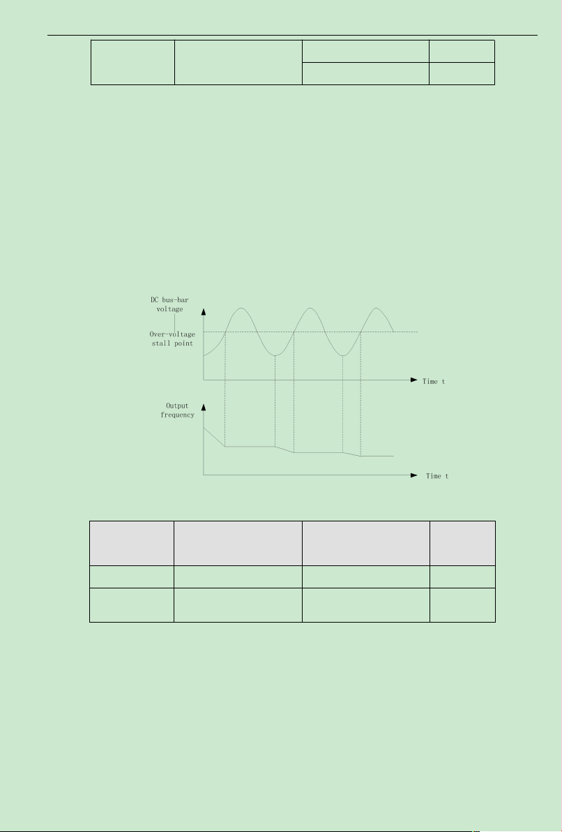
ACD320 user manual Parameter Description
Limit current frequency
drop rate
0.00~200.00Hz/s
F5.05
Over-voltage Stall
Protection Voltage
110~150%(380V) 120%
110~150%(220V) 115%
During the inverter deceleration, the load inertia may cause the actualmotor speed drop rate
lower than the output frequency drop rate, and thereby the motor generates electricity and feeds it
back to the inverter, causing the inverter bus voltage going up and even bus over-voltage
breakdown which then can cause inverter tripping if no provision ismade.
Over-voltage stall protection function is to detect the bus voltage and compare itwith the
stall over-voltage point defined by F5.05 (relative to the standard bus voltage). If it exceeds the
over-voltage stall point, inverter output frequency stop going down, and when the next bus
voltage detected is lower than the over-voltage stall point, the inverter continues to decelerate,as
shown by following figure:
Fig.6-22Over-voltage Stall Function
Function Code Name Setting Range
F5.06 Auto limit current level 100~200% 160%
F5.07
Default
Value
50.00Hz/s
When inverter is running, the actual climbing rate of motor speed is lower than climbing
rate of output frequency because load is too big. If you don抰 take any action, it will cause over
current fault in acceleration then inverter will trip.
Over-current stall protection function is to detect output current and compare it with the
current limit defined by F5.06. If it exceeds the current limit, output frequency drop down
according to F5.07.When it show that output current is lower than limit current, inverterwill
remain normal operation.
- 94-
Page 100
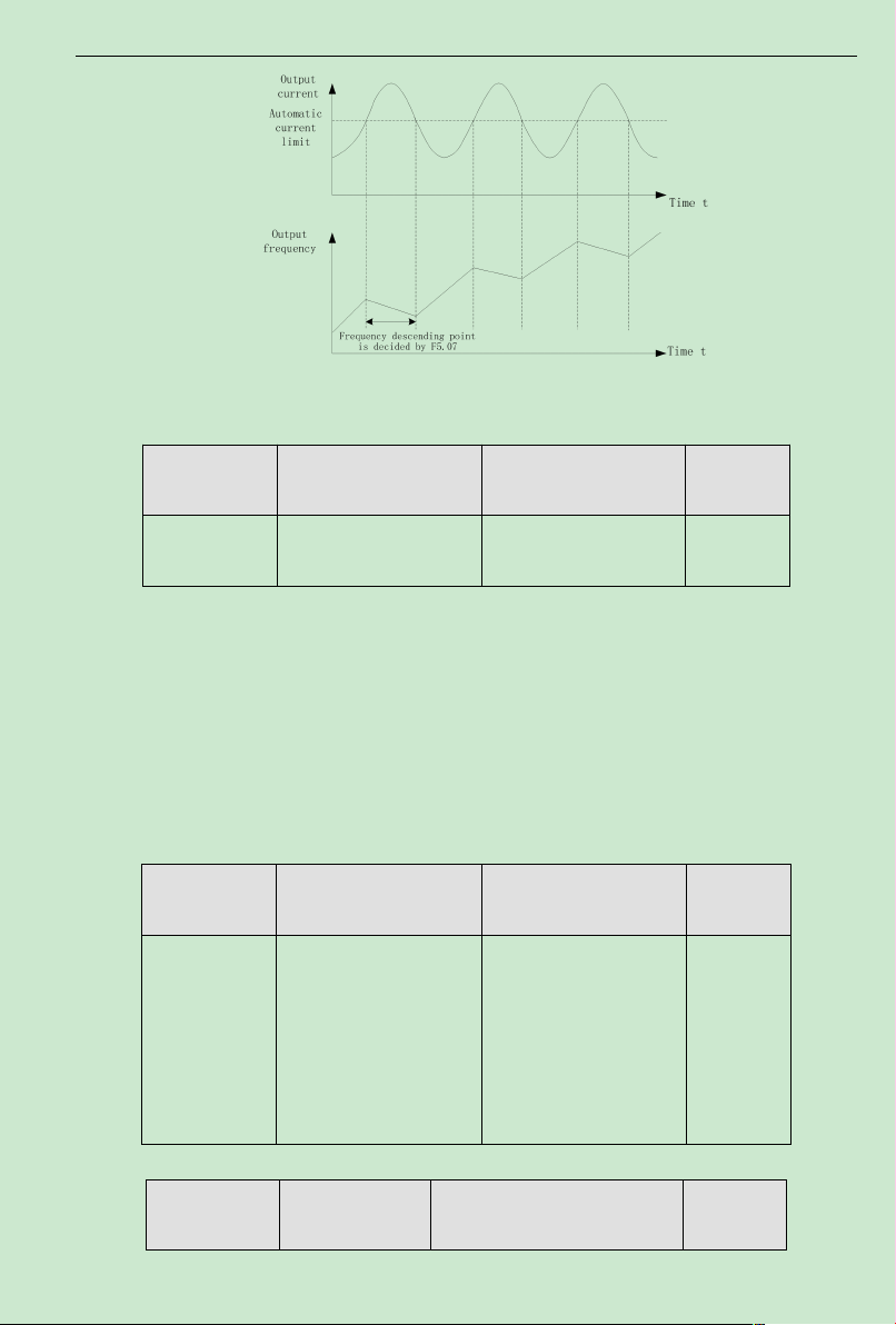
ACD320 user manual Parameter Description
Fig. 6-23 Limit current protection
6.7 F6 Communication Parameters
Function Code Name Setting Range
F6.00 Communication Address
1~ 247,0 is the broadcast
address
When master machine plan to transmit a frame, slave communication address is set to be 0,
it is also broadcast address.All slavemachine inMODBUS will receive this frame but not
response.
Note: slave address is not allowed to set 0.
Local communication address is unique for every slave machinewithin communication
network. This is basis of utilization of point to point communication betweenmaster machine and
inverter.
Default
Value
1
Function Code Name Setting Range
0:1200BPS
1:2400BPS
F6.01 Baud rate setting
2:4800BPS
3:9600BPS
4:19200BPS
5:38400BPS
This parameter is used to set transmission rate.
Function Code Name Setting Range
- 95-
Default
Value
3
Default
Value
 Loading...