

Page 1
MT2W™
Long-Range Synthesized
Radio Meter Transmitter
Installation Manual
Web Site: www.kpsystems.com
ISRAEL Office
Email: info@kpsystems.com
Tefen Industrial Park, Tefen 24959
Tel: 972-4-987-3066 Fax: 972-4-987-3692
USA Office:
KP ELECTRONICS INC.
Email: info@kpsystems.com
415 Sargon way , Suite F Horsham PA 19044
Book 144
Approved: Efi
Rev: NEW
21-Oct-15
MT2W™ General Description
MT2W Wire
Register
Wire/Terminal
Green
Green
Red
Red
Black
Black
The MT2W™ is a 2W output power and
-117DBm sensitivity long-range,
synthesized radio-metering transceiver for
narrow band wireless networks in the
VHF 136-174 MHZ frequency band.
At a preprogrammed interval (default is
every hour) the MT2W interrogates the
register to obtain the most recent read,
and transmits the data to the central
receiver.
Unit parameters and meters values are
easily programmed using the GUP5000™
utility-programming software (see the
MT2W ™ Programming Guide) or by the
FTU.
The MT2W™ has one connector (see
Figure 1).
1. Meter Input: The meter input is
either a single three-wire or double
three-wire cable, depending on factory
configuration. These wires connect to
the meter output.
4. If the strongest signal received is only
a weak signal, move the MTU to
another location, wait 20 seconds and
swipe the magnet along the bottom of
the unit again.
5. Repeat step 4 until the location with
the best signal level is found.
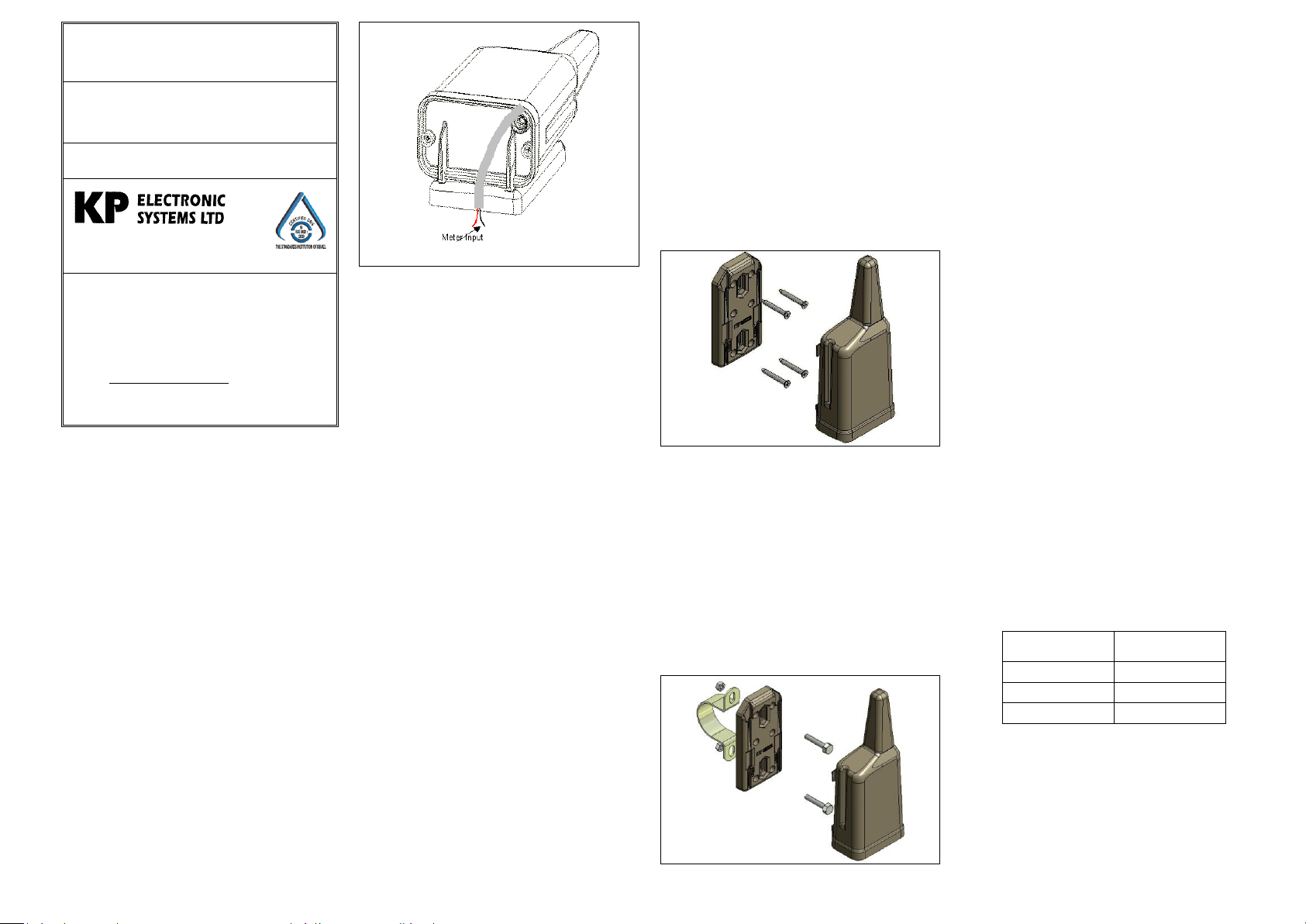
1. Fasten the mounting bracket on the
pipe with two screws and the “Omega”
bracket (See figure 3)
2. Slide the MT2W unit on the mounting
bracket until the 4 clips lock the unit
3. Define the parameters with the field
programmer (FTU100) see the FTU
User Guide
Installing the MT2W™
There are two mounting methods:
Wall mounting
On-pipe mounting
Wall Mounting Installation
4. Swipe the magnet along the bottom of
the MT2W unit. The MT2W wakes
and sends a transmission.
Restrictions
Before installation pay attention to the
following restrictions:
Figure 1: MT2W™ View
1. Do not mount the MT2W on any
metallic surface.
2. Do not run wires next to the MT2W
Preparing for Operation
Before installing the MT2W on site,
perform the following preparations:
1. Setting communication parameters
2. Self test
Setting Communication Parameters
Connect GUP5000 program to the
MT2W (see the MT2W™ Programming
Manual)
Self-Test
See the Field Programmer User Guide for
directions on performing a self-test.
Signal Level Verification
Before attaching the MT2W to the
mounting bracket, verify signal level in
the planned mounting location, by
following these steps:
Figure 2: Wall Mounting
1. Fasten the mounting bracket on the
wall with four screws (See figure 2)
2. Slide the MT2W unit on the mounting
bracket until the 4 clips lock the unit
3. Define the parameters with the field
programmer (FTU100) see the FTU
User Guide
4. Swipe the magnet along the bottom of
the MT2W unit. The MT2W wakes
and sends a transmission.
On-pipe Mounting Installation
antenna.
3. Do not mount the MT2W horizontally.
Always mount unit with antenna facing
upwards.
4. Do not wrap excess wire around the
MT2W.
5. When installing more than a one
MT2W in the same site, make sure
you keep distance of at least 3 ft.
between two adjacent the MT2W units
installed on the same wall/surface.
Wiring
1. Connect the three wires from the
MT2W to the register wires using a
self-stripping insulated connector (3M-
Scotchlock™ or equivalent), or
directly to the register terminals.
Connect as follows:
1. Turn on the FTU101 signal strength
unit.
2. Hold the MT2W in the planned
mounting location (after connecting
the 3 wires to the register – see the
Wiring section for directions how to
connect the MT2W to the register) and
swipe the magnet along the bottom of
the unit.
3. Look at the FTU101 screen, and make
sure you get a good or full signal from
at least one of the repeaters that is
receiving the ID of the MT2W that
was just activated.
Figure 3: On-pipe Mounting
2. Polarity:
If a Passive Pulse type meter is
connected, there is no polarity and
the wires can be connected in any
order
If an Active Pulse type meter is
connected, there is a polarity and the
wires have to be connected in the
following order:
Red wire to the POSITIVE (+) poll
Page 2

Black wire to the NEGATIVE ()
Operating Voltage
8–15 VDC
Standby Current
30µA max.
Tx Current
0.8A max.
Power Output
2W
Freq. Stability
5ppm at operating
temp. range
Operating Temp.
-22F 120F
(-30C 60C)
Storage Temp.
-40F 158F
(-40C 70C)
Weight
0.5 lb.
(230 gr.)
THIS DEVICE COMPLIES WITH
PART 15 OF THE FCC RULES.
OPERATION IS SUBJECT TO THE
FOLLOWING TWO CONDITIONS:
(1) THIS DEVICE MAY NOT CAUSE
HARMFUL INTERFERENCE, AND
(2) THIS DEVICE MUST ACCEPT
ANY INTERFERENCE RECEIVED,
INCLUDING INTERFERENCE THAT
MAY CAUSE UNDESIRED
OPERATION.
NOTE: KP IS NOT RESPONSIBLE
FOR ANY CHANGES OR
MODIFICATIONS NOT EXPRESSLY
APPROVED BY THE PARTY
RESPONSIBLE FOR COMPLIANCE.
SUCH MODIFICATIONS COULD
VOID THE USER’S AUTHORITY TO
OPERATE THE EQUIPMENT.
Figure 4: Wiring
poll.
Technical Specifications
NOTICE
The information in this document has
been carefully checked and is considered
reliable. No responsibility is assumed for
inaccuracies.
KP ELECTRONIC SYSTEMS LTD.
reserves the right to introduce changes in
its products to improve reliability,
function, or design.
KP ELECTRONIC SYSTEMS LTD.
does not assume any liability arising from
the application or use of any of its
products or any product described in this
document, nor does it convey any license
under its patent rights or the rights of
others.
This document contains proprietary
information and may not be reproduced in
any form without prior written consent of
KP ELECTRONIC SYSTEMS LTD.
*Other names and brands may be claimed
as the property of others.
Copyright 2015 by KP ELECTRONIC
SYSTEMS LTD., PO Box 42, Tefen
Industrial Park, Tefen 24959, Israel. All
rights reserved.
FCC INFORMATION TO USER
 Loading...