

Page 1
MT2PIT Installation Manual
1. General Description:
The MT2P is for PIT installation. Before installation check if you have all the MT2P
parts:
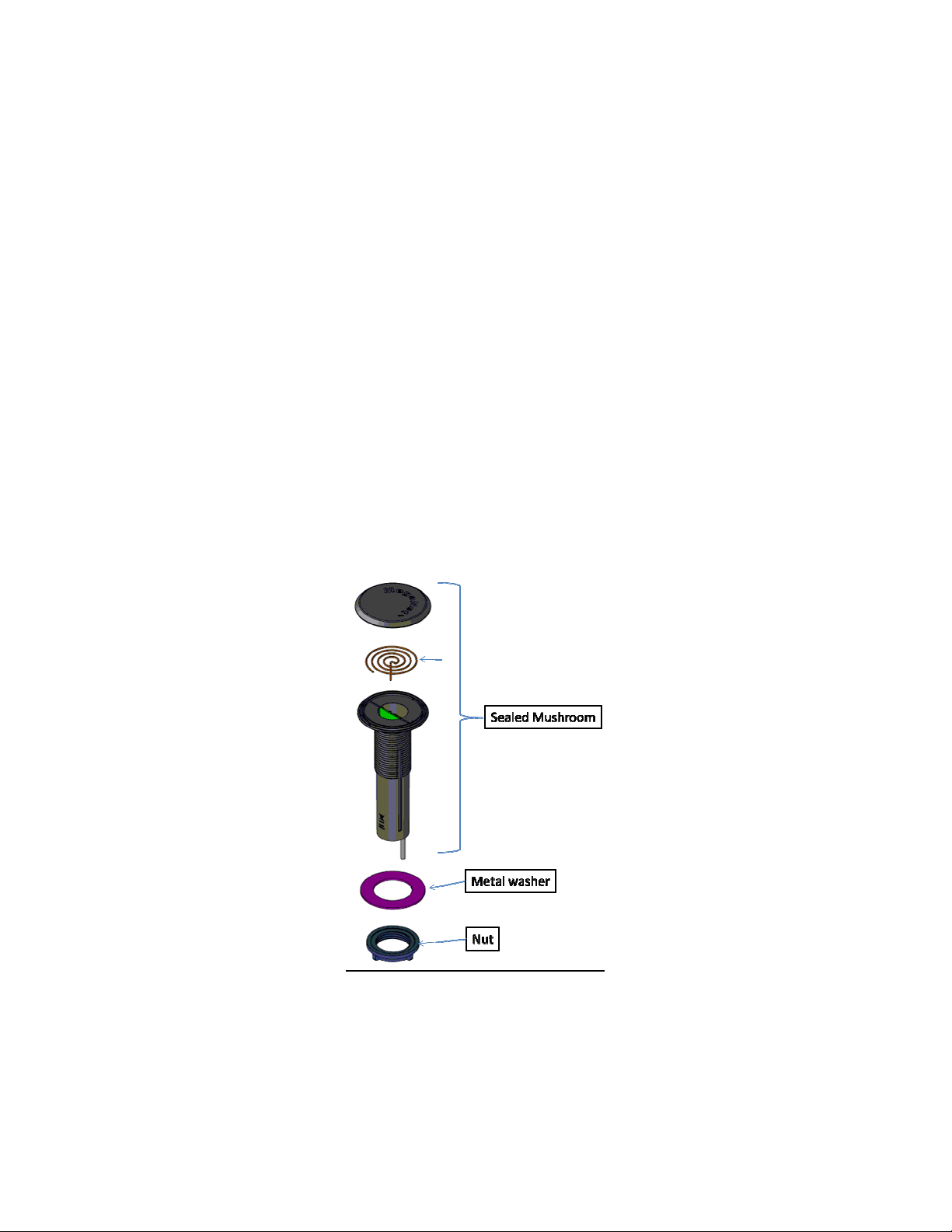
1. The mushroom shape plastic. Check that the unit is not damaged e.g. there
are no scratches or Cracks.
2. Metal washer.
3. Plastic Nut.
4. Cable with NICOR connector. Check the connector pins are straight.
5. Check if there is enough space for the unit beneath the PIT cover.
2. Unit installation
1. Remove and separate the metal washer and the Nut
from the mushroom.
Page 2

2. Insert the mushroom through the cover hole, first the
cable.
3. Screw the Nut with the metal washer above. Tied the
Nut not too much – just be sure that mushroom is tied
to the pit cover.
4. Place the cover on the pit carefully and verify that
nothing touches it.
5. Remove the pit cover and place it on the upper cover
side so the mushroom i.e. ups down.
6. Connect the cable with the meter cable. Make sure
that the two connector ration before pushing one in
the other.
7. Place the lid back and cover the pit.
3. PDA using
The MT2P is sealed without any visual indication e.g. LED. The unit functionality
should be inspected before leaving the pit site. The MT2P is in a very low energy. To
wake up the unit for testing a magnet should be approach the upper side on the unit
from the outside. The MT2P wakes for shot time waiting from a wireless prompt
from the PDA.
4. PDA setting.
Page 3
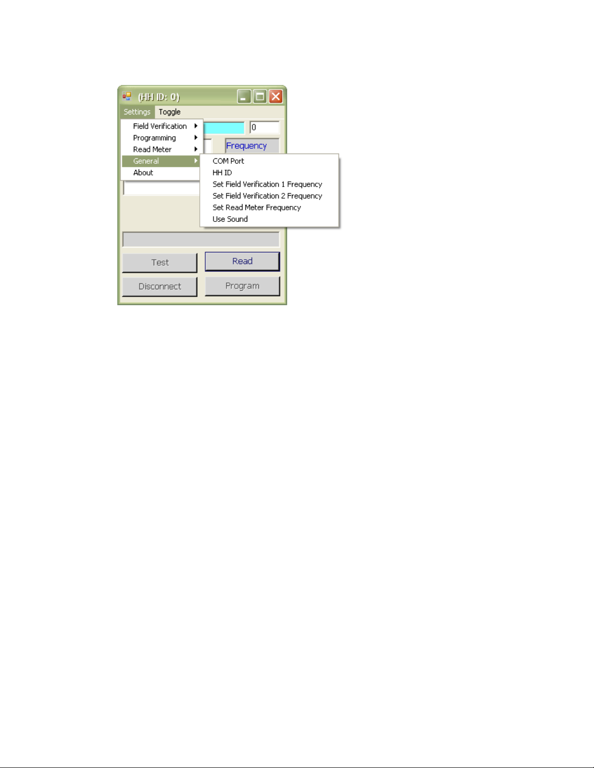
Com Port - To choose the right RSINT05 port.
HH ID - To choose the PDA ID (Paring communication).
Set Field Verification 1 Frequency - To choose the first repeaters frequency.
Set Field Verification 2 Frequency - To choose the second repeaters frequency.
Set Read Meter Frequency - To choose the meter frequency.
Use Sound – Turn on/off sound on received message.
Field Verification (Receive messages from repeaters):
Page 4

Filter - Set filter (to receive certain address \ receive a range of addresses \ receive
all messages the on the air).
Clear Screen – Delete received messages from the screen.
Page 5

5. Programming:
MTWE – For programming encoder transmitters.
MT1W - For programming MT1W transmitters.
MTWP - For programming Pulse transmitters.
Meter Protocols – Show all meters protocols.
Page 6

Read Meter (Receive messages directly from the transmitters):
Filter - Set filter (to receive certain address \ receive a range of addresses \ receive
all messages the on the air).
Clear Screen – Delete received messages from the screen.
Page 7

Toggle (Switch between screens):
Field Verification 1 - Displays the incoming messages that received on first
Frequency.
Field Verification 2 - Displays the incoming messages that received on second
Frequency.
Read Meter - Displays the incoming messages that received on meters frequency.
Page 8

Programming (For transmitters reading and programming):
The top of the screen shows the type of transmitter, version and its parameters
The lower part of the screen is for programming.
Read - Read parameters from the transmitter.
Program - Programming new parameters in the transmitter.
Test - Transmit Test message (VHF/UHF).
Disconnect - End Communications.
Page 9

FCC Part 15.19 Warning Statement- (Required for all Part 15 devices)
THIS DEVICE COMPLIES WITH PART 15 OF THE FCC RULES. OPERATION IS SUBJECT TO THE
FOLLOWING TWO CONDITIONS: (1) THIS DEVICE MAY NOT CAUSE HARMFUL
INTERFERENCE, AND (2) THIS DEVICE MUST ACCEPT ANY INTERFERENCE RECEIVED,
INCLUDING INTERFERENCE THAT MAY CAUSE UNDESIRED OPERATION.
FCC Part 15.21 Warning Statement-
NOTE: THE GRANTEE IS NOT RESPONSIBLE FOR ANY CHANGES OR MODIFICATIONS NOT
EXPRESSLY APPROVED BY THE PARTY RESPONSIBLE FOR COMPLIANCE. SUCH
MODIFICATIONS COULD VOID THE USER’S AUTHORITY TO OPERATE THE EQUIPMENT.
FCC Part 15.105(b) Warning Statement- (ONLY Required for 15.109-JBP devices)
NOTE: This equipment has been tested and found to comply with the limits for a Class B
digital device, pursuant to part 15 of the FCC Rules. These limits are designed to provide
reasonable protection against harmful interference in a residential installation. This
equipment generates, uses and can radiate radio frequency energy and, if not installed
and used in accordance with the instructions, may cause harmful interference to radio
communications. However, there is no guarantee that interference will not occur in a
particular installation. If this equipment does cause harmful interference to radio or
television reception, which can be determined by turning the equipment off and on, the
user is encouraged to try to correct the interference by one or more of the following
measures:
- Reorient or relocate the receiving antenna.
- Increase the separation between the equipment and receiver.
-Connect the equipment into an outlet on a circuit different from that to which the
receiver is connected.
-Consult the dealer or an experienced radio/TV technician for help.
 Loading...