

Page 1
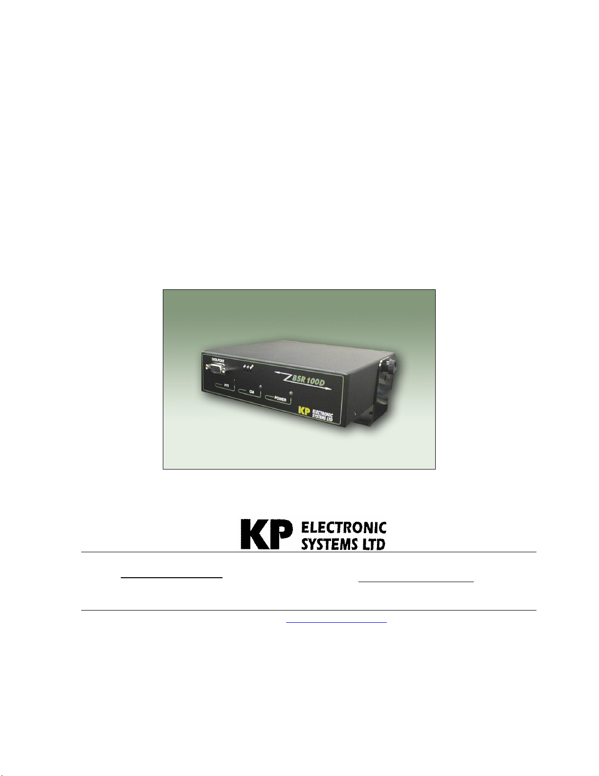
BSR100D™
Wireless VHF / UHF
Radio Modem
User Manual
ISRAEL Office:
Email: info@kpsystems.com
P.O. Box 42, Tefen Industrial Park, Tefen 24959
Tel: 972-4-987-3066 / Fax: 972-4-987-3692
Web Site: www.kpsystems.com
P.N: Book 087 Rev: New
USA Office: KP ELECTRONICS INC.
Email: info@kpelectronics.com
109 Tudor Drive, North Wales, PA 19454
Tel: (215) 542-7460 / Fax: (215) 542-7461
Approved: Moshe Z. 22/05/03
Page 2

Table of Contents
1 GENERAL DESCRIPTION
1.1 BSR100D F
...............................................................................................
UNCTIONS
............................................................................................
4
1.2 F
RONT PANEL DISPLAY
.............................................................................................
4
1.3 R
EAR PANEL DISPLAY
...............................................................................................
5
2 RADIO MODULE DESCRIPTION
3 MODEM MODULE DESCRIPTION
3.1 D
4 PREPARING FOR OPERATION
4.1 RF
ATA PORT INTERFACE
EXPOSURE STATEMENT
.......................................................................................
............................................................................................
..............................................................................
0
4.2 C
ONNECTING ASSEMBLY CABLES
..........................................................................
10
4.3 C
ONNECTING
......................................................
PC/DTE
TO MODEM MODULE
10
4.4 C
4.5 P
ONNECTING POWER SUPPLY
ERFORMING A SELF TEST
.....................................................................................
...............................................................................
.............................................................................
..........................................................................
4
6
7
7
10
1
11
11
5 SETTING COMMUNICATION PARAMETERS
5.1 BSR100D™
....................
RADIO PROGRAMMING GUIDE USING
...............................................
GUP10™
13
1
3
5.1.1 Operating Instructions
.....................................................
1
3
5.1.2 Connecting BSR100D to Gup10
...................................
1
3
5.1.3 Loading Parameter Values
.............................................
1
4
5.1.4 Changing Parameter Values
..........................................
1
4
BSR100D™ Wireless Radio Modem Page 2 User Manual
Page 3

5.1.5 Updating Parameter Value Changes
..........................
4
5.1.6 Confirming Parameter Changes
...................................
4
5.1.7 Activating Self Test
...........................................................
6
5.1.8 On-Screen HELP
...............................................................
6
5.2 BSR100D M
P
ROGRAMMING
5.2.1 Preparing Programming
.................................................
7
5.2.2 COM Port Settings
............................................................
7
5.2.3 COM Port Parameters
.....................................................
7
5.2.4 Primary and Secondary Port Settings Communications Modes
5.2.5 Port Statistics
ODEM PROGRAMMING GUIDE USING
(DFP) S
OFTWARE
.....................................................................
...................
DATARADIO™ F
IELD
.....
1
1
1
1
16
1
1
1
19
20
6 TECHNICAL SPECIFICATIONS
.............................................................................
22
BSR100D™ Wireless Radio Modem Page 3 User Manual
Page 4
1 General Description
The BSR100D is a data radio modem unit designed for high performance, longrange SCADA (Supervisory Control and Data Acquisition) and telemetry
applications. The BSR100D offers the advantage of distanced communications
using long-range VHF and UHF frequencies with data modem.
1.1 BSR100D Functions
BSR100D functions include the following:
• Receives and transmits DRCMSK (Differential Raise Cosine Minimum
Shift Keying) and DF (Direct Frequency) modulation
• Performs receiving and transmitting frequency programming changes
• RSSI output
• Visual control
• Channel monitor control
• PTT control
• On/Off indicator
• Data speeds of 4800 to 19200 bps (9600bps maximum in half channels)
using a standard RS-232 interface
• Power output of 10 watt
• Half duplex or simplex operations
• Transmit control via Request-to-Send (RTS)
• Online diagnostic monitoring
• Offline local and remote diagnostics
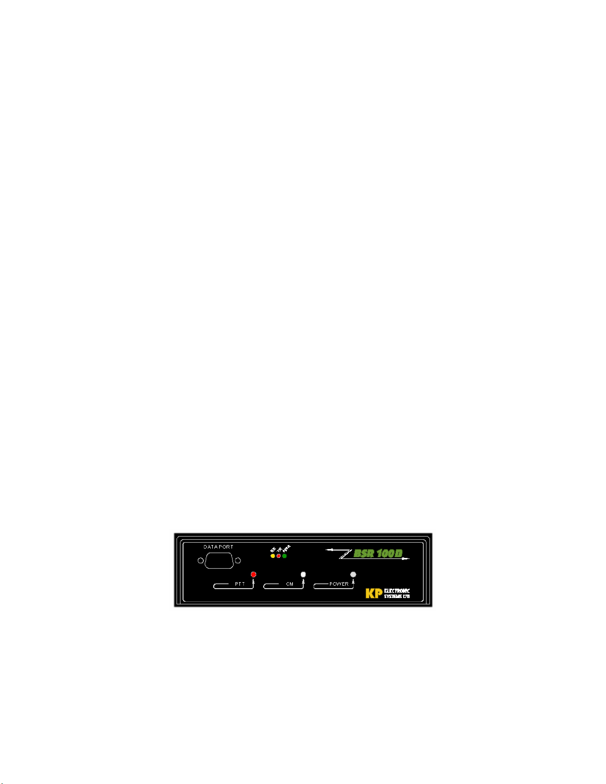
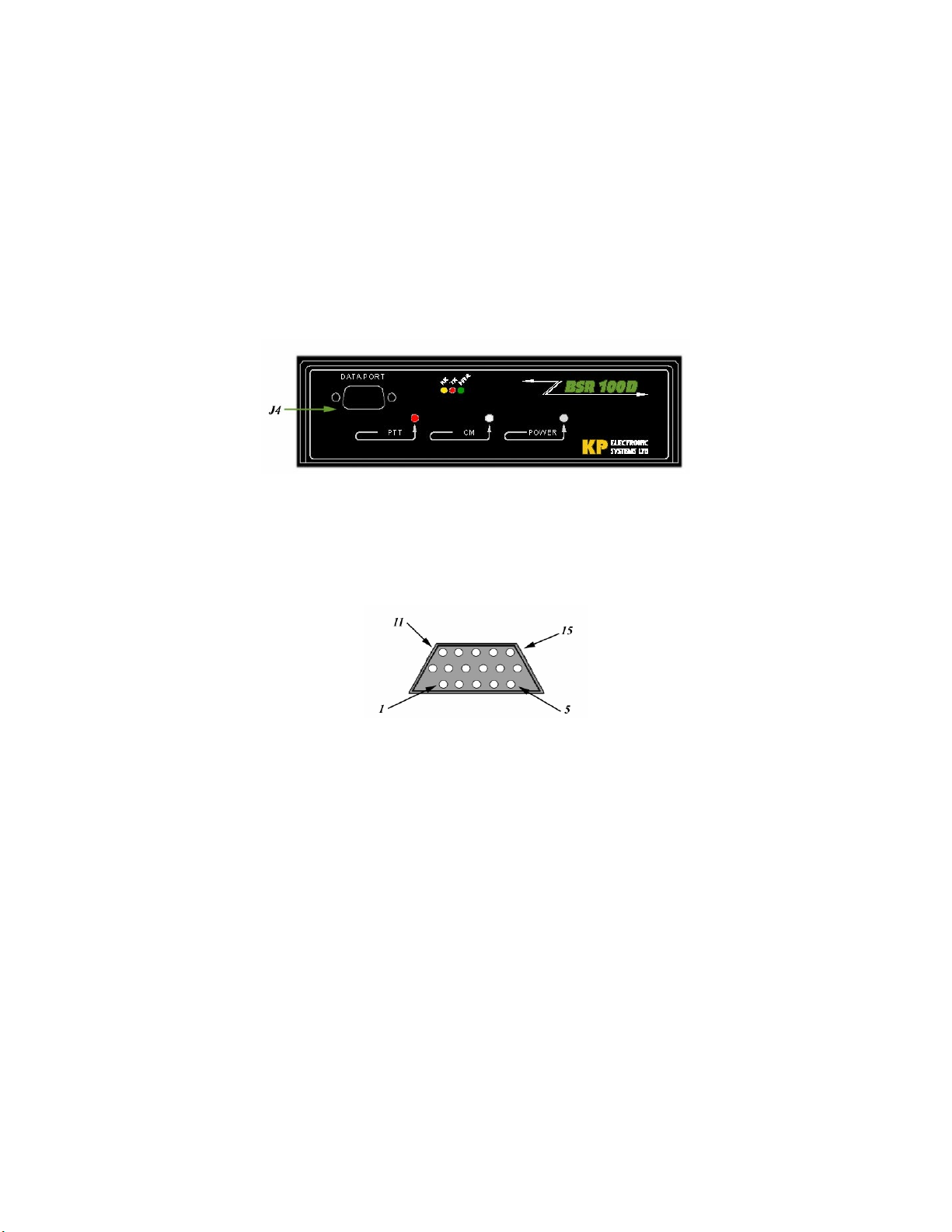
1.2 Front Panel Display
The front panel includes three large LED indicators for radio operations, three
smaller LED indicators for modem operations and a 15-pin data port (see
Figure 1: Front Panel Display and Table 1: Front Panel LED Indication for
full explanation).
Figure 1: Front Panel Display
BSR100D™ Wireless Radio Modem Page 4 User Manual
Page 5
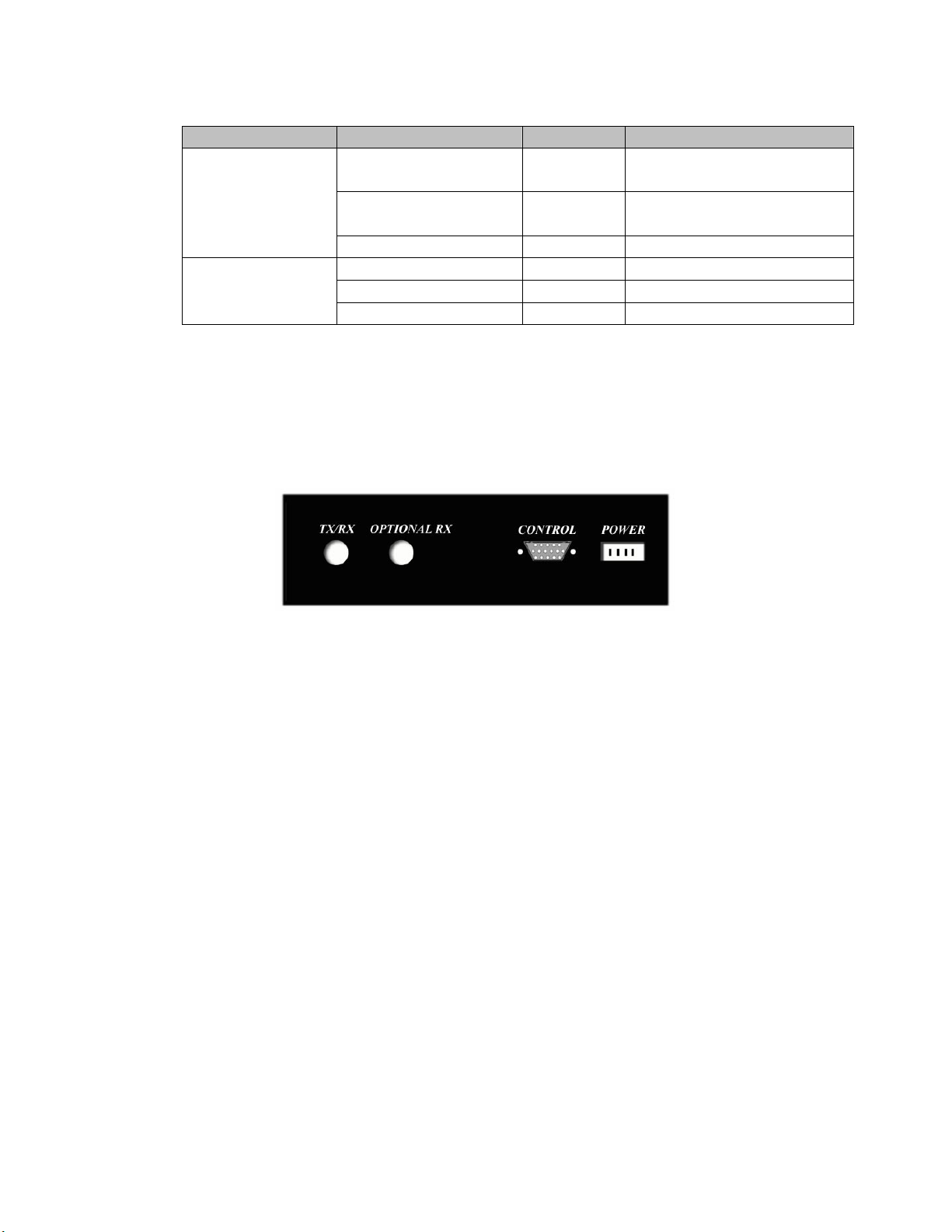
Table 1: Front Panel LED Indication
Functionality Indicates LED Description
Push to talk (PTT) Red/Off Radio transmit/receive
mode
Radio
Channel Monitor
Green/Red Monitors channel activity
(CM)
Power Green/Red DC power
Receive (RX) Yellow Unit is receiving signal
Modem
Transmit (TX) Red Unit is transmitting signal
Power (PWR) Green DC power is applied
1.3 Rear Panel Display
The back panel includes cable connection for Tx/Rx mode with an optional
Rx plug, a 15-pin control connector and power outlet.
Figure 2: Rear Panel Display
BSR100D™ Wireless Radio Modem Page 5 User Manual
Page 6
2 Radio Module Description
The BSR100D has a built in radio module that acts as a VHF/UHF transceiver
and operates as a two-way base station in half duplex mode at remote central
stations and repeaters.
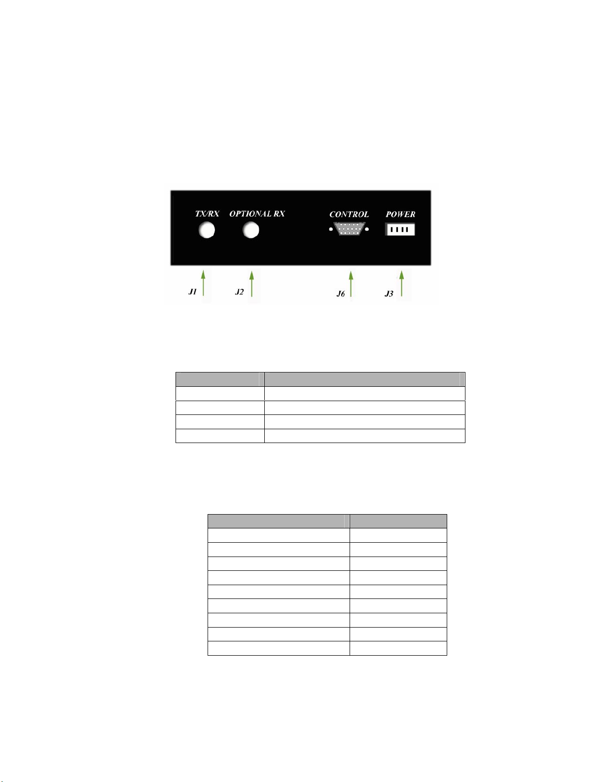
The BSR100D™ has four sets of radio connectors in the rear of the unit: J1,
J2, J3, J6 (see Figure 3: Radio Connectors J1, J2, J3 & J6 and Table 2: Radio
Connector Description for full explanation).
Figure 3: Radio Connectors J1, J2, J3 & J6
Table 2: Radio Connector Description
Connector Function
J1 BNC connector for TX/RX antenna
J2 Additional RX plug for antenna
J3 12.5 VDC power supply
J6 15-pin control connector
The J6 is a D-type 15-pin panel connector that connects the following:
Table 3: J6 Pin Description
Connector Pin
PTT1 1
GND 2, 5, 7, 11, 13, 15
RS232 IN 3
RS232 OUT 4
+VB 6
METER OUT 8
NC 9, 10
AUDIO IN 12
DATA OUT 14
BSR100D™ Wireless Radio Modem Page 6 User Manual
Page 7
3 Modem Module Description
The BSR100D has a built-in wireless modem that provides a high-speed data link
suitable for a wide variety of applications with system security for diagnostics
reporting.
3.1 Data Port Interface
The BSR100D modem component is equipped with a J4 15-pin data port
interface. The J4 is used for connection between the radio modem and PC for
set-up and data communications (see Figure 4: Data Port Interface).
Figure 4: Data Port Interface
Set-up and data communications require two separate cables to be used. Each
cable is labeled SET-UP or PC DATA cable and is equipped with a male 15pin cable connection to connect directly to the J4 interface, and a
corresponding female 9-pin COM port connector to connect to the PC.
Figure 5: Data Port Connector Diagram
Following is a detailed pin description and data port cable description:
Table 4: J4 Pin Description
BSR100D™ Wireless Radio Modem Page 7 User Manual
Page 8

Pin Name Pin Name Pin Name
1 Ground 6 Ground 11 CS 0
2 Rx Data 7 Clear to Send
12 CS 1
(CTS)
3 Tx Data 8 Request to Send
13 CS 2
(RTS)
4 Test Audio 9 Data Carrier
Detect (DCD)
14 Received Signal
Strength Indicator
(RSSI)
5 B+ Power 10 B+ Power 15 DTR
Programming
Figure 6: Data Port Cable Description
Table 5: Interface Signal Description
Name Description
B+ Power (input) 10 to 16 VDC (13.3V nominal maximum) 2.5A (Not
Applicable)
RX Data Receive data from BSR100D to DTE
TX Data Transmit data from DTE to BSR100D
CTS Asserted when the BSR100D is ready to accept TX data
RTS Causes the BSR100D to transmit when asserted by the DTE
DCD Asserted by the BSR100D when a data signal is being
received
BSR100D™ Wireless Radio Modem Page 8 User Manual
Page 9

DTR Data Terminal Ready. Asserted by the BSR100D Field
Programming Software to select set-up mode (Don’t connect
to this pin for user application)
Test Audio Output signal used during adjustment and testing
RSSI Output signal used during testing
BSR100D™ Wireless Radio Modem Page 9 User Manual
Page 10

4 Preparing for Operation
Before installing the BSR100D™, it is suggested that the following preparations are
performed:
• Connecting assembly cables
• Connecting PC to Modem Module DTE
• Connecting power supply
• Performing a self test
4.1 RF exposure statement
Power listed is Conducted. For mobile operation, the antenna used for this
transmitter must not exceed 2 dBi and must be installed to provide a separation
distance of at least 80 cm from all persons and must not be co-located or operating
in conjunction with any other antenna or transmitter. Installers and end-users must
be provided with antenna installation instructions and transmitter operating
conditions for satisfying RF exposure compliance.
For Fixed Base operation, the antenna(s) used for this transmitter must not exceed 6
dBi and must be installed to provide a separation distance of at least 1.25 m from all
persons and must not be co-located or operating in conjunction with any other
antenna or transmitter. Installers and end-users must be provided with antenna
installation instructions and transmitter operating conditions for satisfying RF
exposure compliance.
4.2 Connecting Assembly Cables
To connect the assembly cables:
1. Connect one end of the ρ=50 Ohm cable to J1, the Rx/Tx BNC connector.
2. Connect the other end of the ρ=50 Ohm cable to the 50 Ohm load, according
to its application wiring diagram
4.3 Connecting PC/DTE to Modem Module
To connect the assembly cables:
1. Connect the cable labeled PC DATA to the 15-pin J4 DTE connector on the
front panel of the BSR100D’s modem module (see Figure 7).
2. Connect the other end of the PC DATA cable to the 9-pin serial COM port at
the rear of the computer.
BSR100D™ Wireless Radio Modem Page 10 User Manual
Page 11

Figure 7: PC/ Modem Module DTE Connection
4.4 Connecting Power Supply
To connect the DC plug to the J3 DC Power Connector:
1. Connect one end of the cable to J3, the four-pin rear panel connector.
2. Connect the other end of the cable to a 12.5 VDC, 5A power source (power
supply/battery)
4.5 Performing a Self Test
To perform a self test:
1. Switch on the 12.5 VDC power supply
2. Observe the Self-Test LEDs (see Figure 8: Self-Test LEDs and Table 6:
Self-Test LEDs for full description)
Figure 8: Self-Test LEDs
Table 6: Self-Test LEDs
LED Indicator Status
LED PTT
ON (red) Tx mode
OFF Rx mode
2 Flashes Overload (optional)
3 Flashes Predriver/Driver
1 Flash Time out timer
4 Flashes PLL
4 Flashes Synthesizer
BSR100D™ Wireless Radio Modem Page 11 User Manual
Page 12

LED Indicator Status
Power LED
Green Normal
Red Dead Battery
CM LED
Green Free
Red Channel Monitor
Flashes red/-green RF/IF Amplifiers
In addition to the signals in Table 6: Self-Test LEDs, there is an error-status word in the
Gup10™ Utility Program (see following Section 5 Setting Communication Parameters)
BSR100D™ Wireless Radio Modem Page 12 User Manual
Page 13

5 Setting Communication Parameters
5.1 BSR100D™ Radio Programming Guide Using GUP10™
Using KP’s Gup10 Utility Program, the BSR100D™ parameter values listed
below can be programmed or modified.
• Transmit frequency (MHz)
• Receiver frequency (MHz)
• Tx time out (0-240 sec)
Connecting RADIO SET-UP cable using KP’s RS232 adaptor (RSINT001™)
are configured between the BSR100D and a PC (see Figure 9: BSR100D/PC
Connection Configuration).
Figure 9: BSR100D/PC Connection Configuration
5.1.1 Operating Instructions
• Connecting BSR100D to Gup10 (utility
program)
• Loading Parameter Values
• Changing Parameter Values
• Updating Parameter Value Changes
• Confirming Parameter Value Changes
• Activating Self Test
5.1.2 Connecting BSR100D to Gup10
Connect BSR100D™ to a PC using the RSINT001 adaptor
and cables
Click Start¾Programs¾KP Utilities¾GUP10.
The GUP10 main screen displays the device type, version,
status device diagnostics and parameters (see Figure 10:
Gup10 Main Screen)
BSR100D™ Wireless Radio Modem Page 13 User Manual
Page 14

Figure 10: Gup10 Main Screen
5.1.3 Loading Parameter Values
Parameter values must be loaded after connecting the
Gup10 utility software.
To Load Parameter Values
1. From the Gup10 main screen, click Prompt?
(Alt P)
2. Click Read (Alt R). The name of the device
type, version, and suitable parameters are
displayed
5.1.4 Changing Parameter Values
Parameter values can be changed as required. Type the
new parameter value in the designated parameter text box.
5.1.5 Updating Parameter Value Changes
1. Click Send (Alt S). The Send Warning
dialog box displays “Are you sure?”
2. Choose one:
• Click Yes, to update
parameter changes
O
R
• Click No, to return to the
Gup10 main screen without
updating changes
5.1.6 Confirming Parameter Changes
Ensure that any parameter value changes made are updated.
To confirm parameter changes click Read (Alt R) from the
BSR100D™ Wireless Radio Modem Page 14 User Manual
Page 15

Gup10 main screen. The Gup10 main screen displays the
updated parameter values.
BSR100D™ Wireless Radio Modem Page 15 User Manual
Page 16

5.1.7 Activating Self Test
After parameter values are loaded, perform a self-test:
1. Disconnect BSR100D from the PC
2. Press the self-test button
3. Observe the self-test led
5.1.8 On-Screen HELP
To view a brief explanation of any BSR100D parameter,
click the required parameter text box. The cursor will
appear in the designated text box, and the valid parameter
range, with a brief explanation, displays at the bottom of
the screen.
5.2 BSR100D Modem Programming Guide Using DATARADIO™
Field Programming (DFP) Software
The DATARADIO field programming (DFP) software provides programming
and diagnostics for the BSR100D Radio Modem. The DFP software allows
the user to edit and program user programmable settings, interactively tune
modem, and monitor diagnostic data from the BSR100D (See Figure 11: DFP
Software Startup Screen).
Figure 11: DFP Software Startup Screen
This manual assumes the DFP software has been installed on the user’s PC
with at least one operational serial COM Port available.
BSR100D™ Wireless Radio Modem Page 16 User Manual
Page 17

5.2.1 Preparing Programming
To commence programming of the BSR100D modem
module parameters, connect the MODEM SET-UP cable
(refer to Section 3.1 Data Port Interface) to the J4
connector on the front panel of the BSR100D. The
corresponding 9-pin connection on the SET-UP cable is
connected to the PC serial COM port.
5.2.2 COM Port Settings
BSR100D programming is done through the PC’s primary
COM port. Primary and secondary COM ports are
configured with the DFP software.
The programming cable is connected from the set-up port
on the BSR100D to the PC’s COM port configured as the
primary port. The Port Setting Screen of the FPS is
accessed via the Utilities pull-down menu (see Figure 12:
DFP Software Port Setting Screens).
The Port Setting Screens are used to configure the PC’s
serial COM ports. COM port assignments are displayed in
the bottom status bar of the DFP software screen.
Figure 12: DFP Software Port Setting Screens
5.2.3 COM Port Parameters
COM Port
Selects COM Port number (COM 1-4) for primary and
secondary COM ports (see Figure 12: DFP Software Port
Setting Screens)
Baud Rate
Selects the communication speed for primary and
secondary COM ports
BSR100D™ Wireless Radio Modem Page 17 User Manual
Page 18

Data Bits
Selects the number of data bits (4-8) transmitted or
received for the primary and secondary COM ports
BSR100D™ Wireless Radio Modem Page 18 User Manual
Page 19

Parity
Selects transmission or reception of any parity bits for the
primary and secondary COM ports
Stop Bits
Selects number of stop bits (1 or 2) transmitted or received
for the primary and secondary COM ports
DTR Enable
Used to assert DTR line of the RS232 port when the port is
open for the primary and secondary COM ports
Swap COM Ports
Selecting the Swap COM Ports button moves the secondary
COM port setting to the primary COM port (and moves the
primary COM port to the secondary settings). Since the
BSR100D programming is done through the primary COM
port, this is useful when two units are connected to the
primary and secondary COM ports. A swap COM port
allows the second unit to be programmed without switching
programming cables.
5.2.4 Primary and Secondary Port Settings Communications Modes
The mode drop down menu configures the communication
mode for the primary and secondary PC Port (See Table 7:
Communication Modes).
Table 7: Communication Modes
Mode Description
Sync/ESC with no
Handshake (HS)
Sends data using Sync/byte-stuffing
protocol with out HS
Buffered with no HS Sends buffered data without HS (this mode
required for DOX operation)
Sync/Esc with RTS/CTS HS Sends data using the Sync/Esc byte-
stuffing protocol with RTS/CTS HS
Buffered with RTS/CTS HS Sends buffered data with RTS/CTS
hardware HS
Sync/Esc with flow control
HS
Buffered with flow control
H/S
Sends data using the Sync/Esc byte-
stuffing protocol with flow control HS
Sends buffered data with flow control
hardware HS
BSR100D™ Wireless Radio Modem Page 19 User Manual
Page 20

5.2.5 Port Statistics
Port statistics show current parameters of the PC’s primary
and secondary COM ports.
RTS
Shows the current state of the RTS line. RTS is an output
from the PC.
DTR
Shows the current state of the DTR line. DTR is an output
from the PC.
CTS
Shows the current state of the CTS line. CTS is an input to
the PC.
Data Set Ready (DSR)
DSR shows the current state of the DSR line. DSR is an
input to the PC.
DCD
DCD shows the current state of the DCD line. DCD is an
input to the PC.
Bytes Transmitted
Bytes Tx’ed shows the number of bytes (characters)
transmitted since the port was last open or cleared.
Bytes Received
Bytes Rx’ed shows the number of bytes (characters)
received since the port was last open or cleared.
Framing Errors
Framing Errors shows the number of farming errors
received since the port was last open or cleared.
Figure 13: Port Statistics Screen
BSR100D™ Wireless Radio Modem Page 20 User Manual
Page 21

Dribble Bytes
Dribble Bytes shows the number of extra (not expected)
bytes (characters) received since the port was last open or
cleared.
BSR100D™ Wireless Radio Modem Page 21 User Manual
Page 22

6 Technical Specifications
General
Band BSR100D VHF BSRU100D UHF
Frequency Range 136-174 MHz 410-510 MHz
Channel Bandwidth 12.5 KHz
Programming Fully PC programming
FCC Type Acceptance H78KPBSR100 H78KPBSRU100
ETSI 300.113
Operating Voltage 10-15 VDC
Current Consumption 150mA STBY; 3A TX 160mA STBY; 3A TX
Diagnostics Overload trouble, driver fault, timeout, PLL lock, dead
battery, power trouble, RSSI
Frequency Stability ± 2.5ppm @ -30 degrees Celsius to 60 degrees Celsius
(23 degrees Fahrenheit – 141degrees Fahrenheit)
Receiver
Sensitivity -117dBm @12 dB SINAD
Selectivity 65 dB for 12.5 KHz
Inter-modulation 75 dB
Spurious and Image
Rejection
Transmitter
RF Output Power 1-10 Watts
Spurious Emission -80 dB
Modem
Data Rate 4800, 9600
Modulation DRCMSK
Bit Error Rate Better than 1 x 10⁻⁵ @ 1.0µ V @ 4800 , 12.5 KHz
Signal Level EIA RS –232C
Data Format Asynchronous, serial, transparent
Word Length 7 or 8 bit words, 1 or 2 stop bits
Parity Even, odd, or none
Handshake RTS-CTS
RTS/CTS Delay 15 msec
Diagnostics Power, TX RX, internal temp
75 dB
BSR100D™ Wireless Radio Modem Page 22 User Manual
Page 23

Physical Dimension
Size 169x150x44 mm ( 6.6”x5.9”x1.7)
Weight 0.65 Kg (1.44 Lbs)
BSR100D™ Wireless Radio Modem Page 23 User Manual
 Loading...