

Page 1

TROUBLESHOOTING GUIDE
FOR PR-23 ALL MODELS
1 (14)
January 9, 2015
K-PATENTS OY Postal Address: P.O.Box 77, FI-01511 Vantaa, Finland Street Address: Elannontie 5, FI-01510 Vantaa, Finland Tel. int.+358 207 291 570
Fax int.+358 207 291 577 info@kpatents.com www.kpatents.com Vat No. FI03035575 Business ID 0303557-5 Registered in Helsinki
TROUBLESHOOTING GUIDE FOR PR-23 ALL MODELS
Contents
1. Instrument diagnostics ................................................................................................................................ 2
2. Interpreting the Optical Image and Diagnostic Values ............................................................................... 3
3. Prism washing ............................................................................................................................................ 8
4. Typical Faults and Causes ....................................................................................................................... 11
5. Preventive Maintenance Inspection Plan ................................................................................................. 13
Page 2
TROUBLESHOOTING GUIDE
FOR PR-23 ALL MODELS
2 (14)
January 9, 2015
K-PATENTS OY Postal Address: P.O.Box 77, FI-01511 Vantaa, Finland Street Address: Elannontie 5, FI-01510 Vantaa, Finland Tel. int.+358 207 291 570
Fax int.+358 207 291 577 info@kpatents.com www.kpatents.com Vat No. FI03035575 Business ID 0303557-5 Registered in Helsinki
1. Instrument connectivity for diagnostics
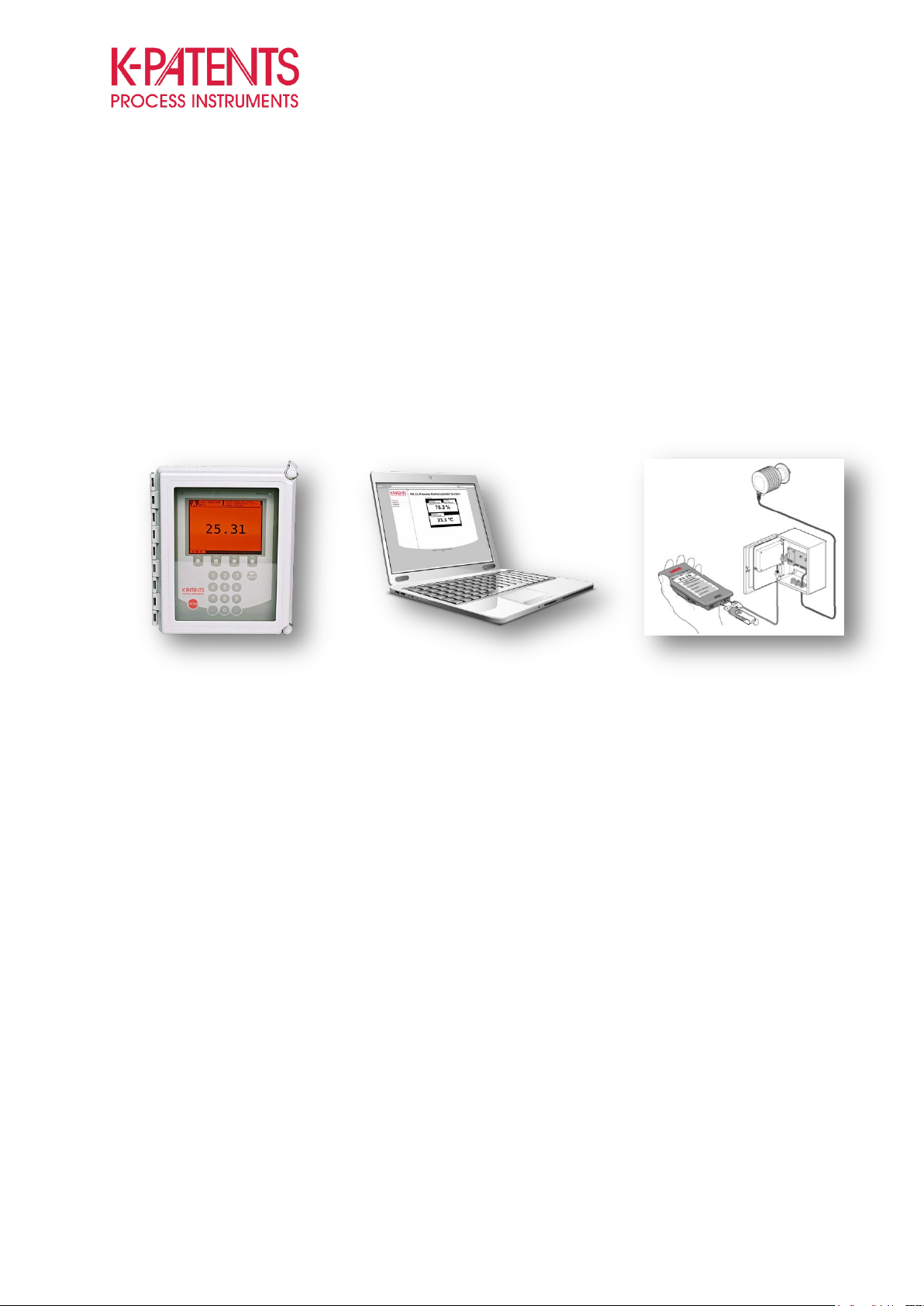
The K-Patents Process Refractometers PR-23 include an Indicating transmitter unit (DTR), which offers the
most convenient channel to diagnose and troubleshoot faulty operation of the refractometer. The same
information can also be obtained through an internal built-in web server using a laptop. Furthermore, FC-11
Field communicator can be connected to the transmitter for data logging and to obtain more detailed
diagnostic information. The FC-11 is specially designed tool for service, troubleshooting and configuration of
the K-Patents instruments.
Figure 1 Instrument diagnostics can be obtained through the transmitter, a laptop or FC-11.
The instrument’s web server can be reached through the instrument’s IP-address. The default IP-address for
the PR-23 series is 192.168.23.254. The FC-11 automatically connects to the instrument if the address has
not been changed. To obtain connection between instrument and laptop, type the IP-address on the
search/address field of the browser. The webpage opens in all common web browsers. Sometimes the IPaddress of the computer needs to be configured prior to establishing the connection, especially if there is no
router between the instrument and the laptop.
1.1 IP configuration for Windows 7
The connection to the instrument is established using a router between the laptop and the instrument. In the
event no router is available or there are other difficulties in connecting to the instrument, follow the
instructions below.
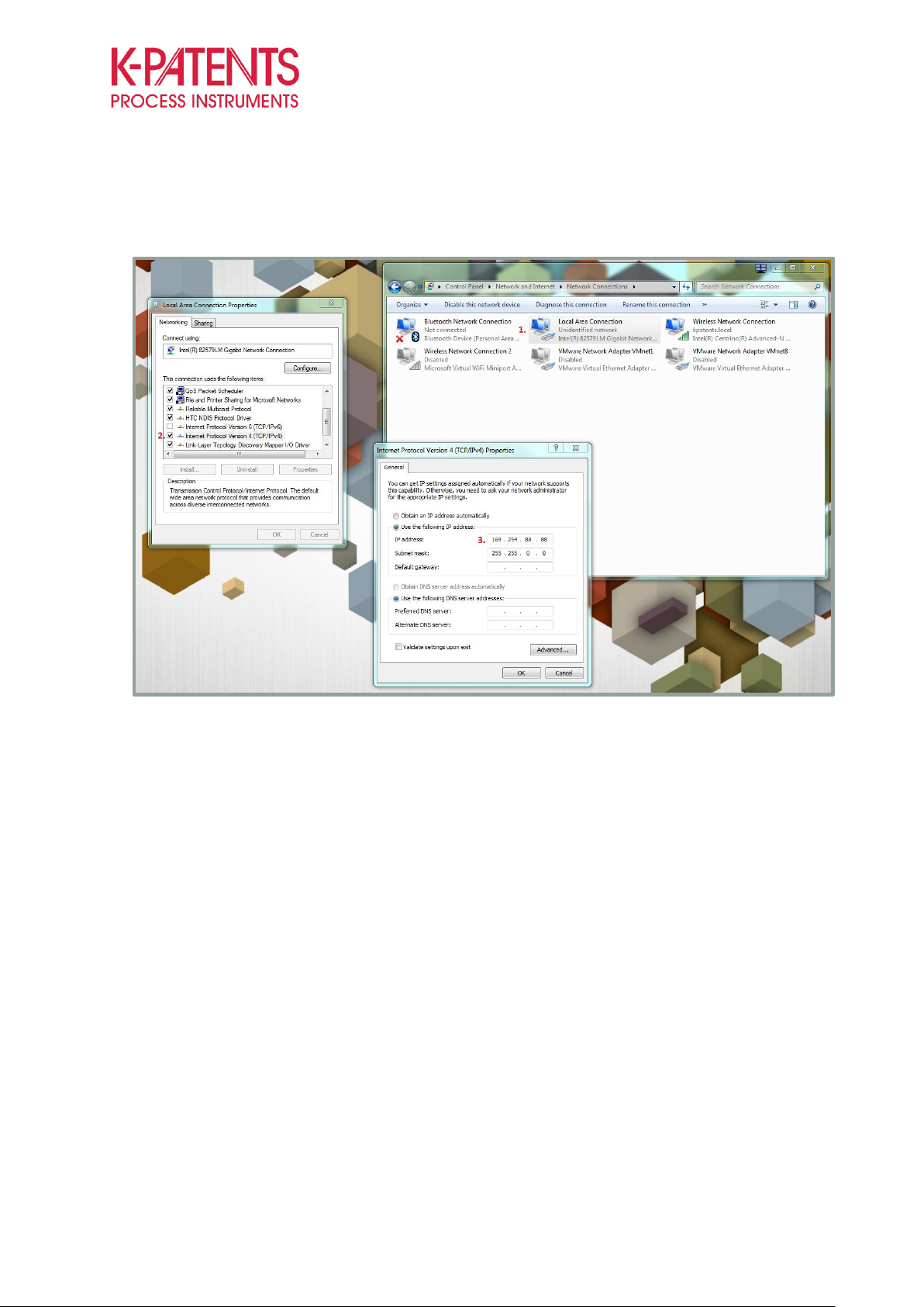
The IP-address of the computer can be configured through Windows control panel by selecting Network and
Sharing Centre, adapter settings and choosing LAN connection properties with a right click of the mouse (1).
Then select the Internet Protocol Version 4 (TCP/IPv6) and click properties (2). This will open a window that
allows configuring the IP-address. The first two sets of numbers in the IP-address should be the same as in
the sensor’s IP-address, however, the IP-addresses should not be totally identical (3). The Subnet mask is
Page 3
TROUBLESHOOTING GUIDE
FOR PR-23 ALL MODELS
3 (14)
January 9, 2015
K-PATENTS OY Postal Address: P.O.Box 77, FI-01511 Vantaa, Finland Street Address: Elannontie 5, FI-01510 Vantaa, Finland Tel. int.+358 207 291 570
Fax int.+358 207 291 577 info@kpatents.com www.kpatents.com Vat No. FI03035575 Business ID 0303557-5 Registered in Helsinki
given automatically. Make sure that the PC’s wireless function is disabled.
Figure 2 Configuring of instrument’s IP-address when connecting without router
1.2 Web Browser Display
The web browser gives you access to the “remote panel” of the instrument, which mimics the user interface
on the actual transmitter. The simulated panel can be operated by pressing the “soft keys” with your mouse.
You can access all the information through the webpage, but also the printable version of the calibration
verification is available on the webpage.
2. Interpreting the Optical Image and Diagnostic Values
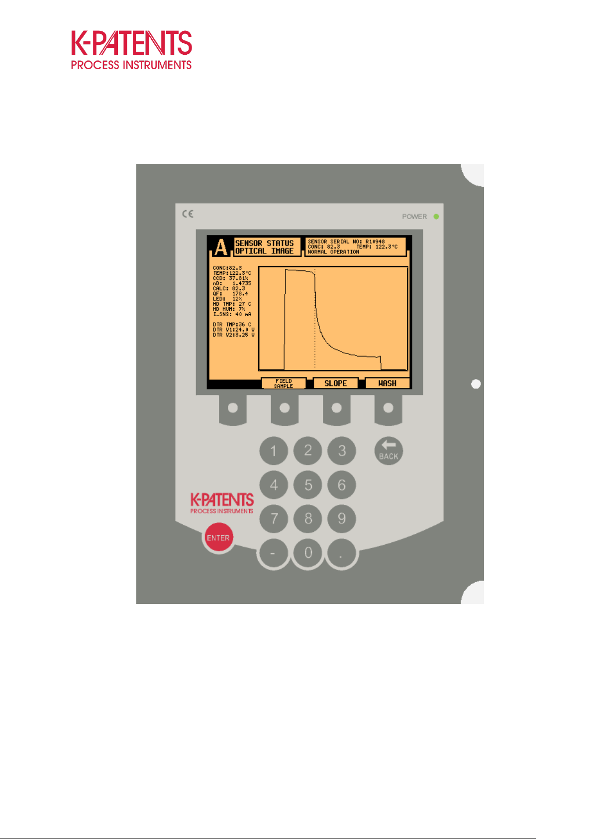
All tools for troubleshooting and performance check of the instrument can be found under “sensor status” in
the transmitter menu (Press MENU 3 SENSOR STATUS). The “sensor status” display shows the optical
image, slope and diagnostical values. You can also activate manual wash from this display to check
functioning and efficiency of the prism washing.
The optical image can be used for inspecting the condition of the optics. The diagnostic values can be used
to evaluate the stability of the measurement and condition of the electronics and optical components of the
Page 4
TROUBLESHOOTING GUIDE
FOR PR-23 ALL MODELS
4 (14)
January 9, 2015
K-PATENTS OY Postal Address: P.O.Box 77, FI-01511 Vantaa, Finland Street Address: Elannontie 5, FI-01510 Vantaa, Finland Tel. int.+358 207 291 570
Fax int.+358 207 291 577 info@kpatents.com www.kpatents.com Vat No. FI03035575 Business ID 0303557-5 Registered in Helsinki
instrument.
Figure 3 Sensor status page shows the current diagnostic values and optical image
Page 5
TROUBLESHOOTING GUIDE
FOR PR-23 ALL MODELS
5 (14)
January 9, 2015
K-PATENTS OY Postal Address: P.O.Box 77, FI-01511 Vantaa, Finland Street Address: Elannontie 5, FI-01510 Vantaa, Finland Tel. int.+358 207 291 570
Fax int.+358 207 291 577 info@kpatents.com www.kpatents.com Vat No. FI03035575 Business ID 0303557-5 Registered in Helsinki
2.1 Optical Image and Slope
The optical image can be described as a window to the process medium. However, it also gives information
about the condition of the prism and the optics. Scratches or coating layers on the prism can be identified
from the optical image. Altering shapes are formed with every change in the prism-process interface.
Generally, the instrument has two different optical images, i.e. the raw image and IDS scaled optical image.
The raw image is the real response signal from the fotocells of the CCD-element, which is also unique to
every instrument. Consequently, the IDS image was developed to unify the optical images making the
instrument more user friendly. The IDS image is created by mathematical scaling of the raw image to a
rectangular shape improving the measurement stability on high and low refractive index (RI) ranges.
Figure 4 IDS image on the left and raw image on the right
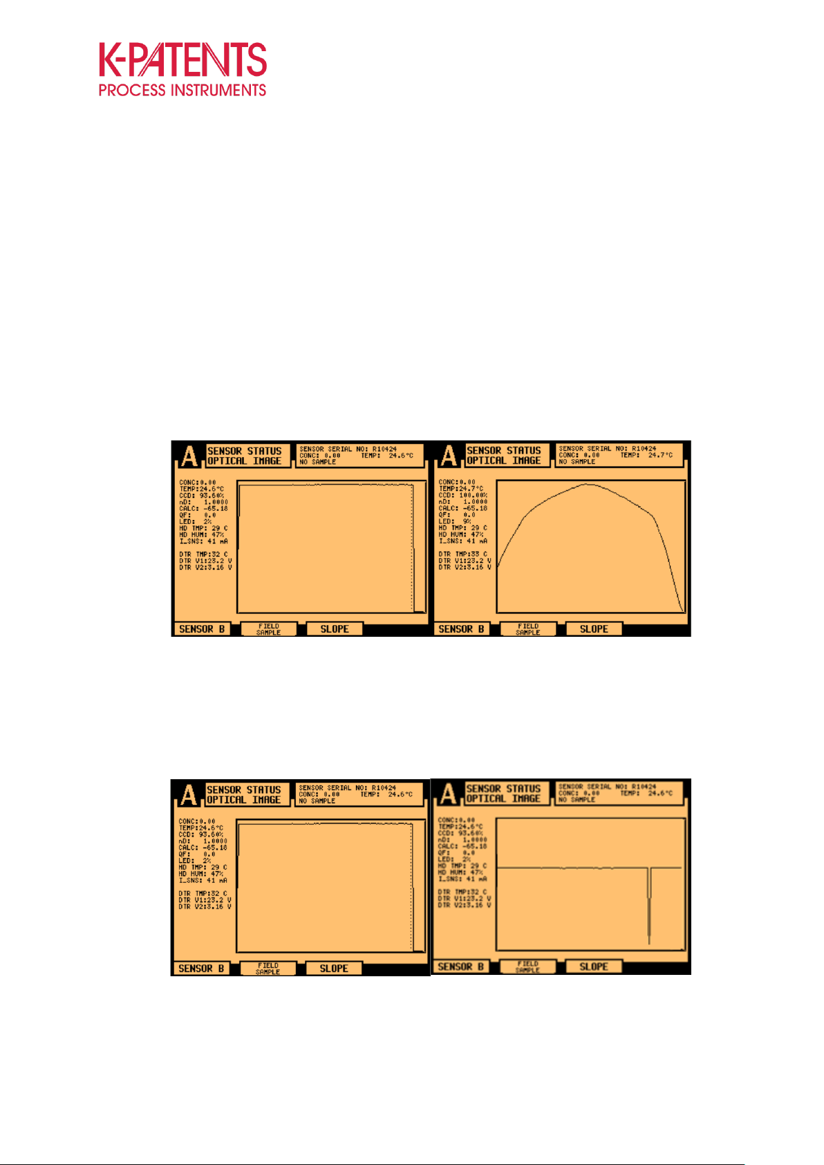
The detection of the measurement point is based on the steepest slope in the optical image (borderline of
activated vs inactivated light reflection). The slope image gives a derivative graph of the optical image that
can be used to examine the quality of the optical image and stability of the measurement.
Figure 5 Optical image and slope without sample
Without a sample on the prism surface, the IDS scaled optical image should always return to “box” shape.
Page 6

TROUBLESHOOTING GUIDE
FOR PR-23 ALL MODELS
6 (14)
January 9, 2015
K-PATENTS OY Postal Address: P.O.Box 77, FI-01511 Vantaa, Finland Street Address: Elannontie 5, FI-01510 Vantaa, Finland Tel. int.+358 207 291 570
Fax int.+358 207 291 577 info@kpatents.com www.kpatents.com Vat No. FI03035575 Business ID 0303557-5 Registered in Helsinki
Any outside light can also affect the shape of the optical image, therefore, the prism should be covered when
inspecting the optical image. If the optical image is not as shown above, the prism should be cleaned with a
glassfiber brush, and inspected for scratches or marks.
Figure 6 Optical image and slope during measurement
During operation the optical image bends at a certain position which depends on the R.I. of the measured
medium. Also a clear dip appears on the slope image. A greater dip on the slope image demonstrates better
optical image quality and more stable measurement.
The QF-value is related to the quality of the optical image and the slope (higher QF is better). However, the
sharpness of the slope and the QF-value can vary significantly depending on the application. The best way
to exploit the QF-values is to follow and record the changes in the QF which can reveal the changes on the
prism surface.
If the prism is damaged, there can be several dips on the slope which can disturb the measurement. As long
as the slope of the real measurement point is steep, the measurement is not lost. In case of prism coating
the slope typically weakens which can lead to losing of the measurement. However, low optical image, high
spikes, irregular form of the optical image or very weak slopes indicate that actions are required. Typically,
visual check of the prism condition and cleaning it with a glass fiber brush is enough to resolve measurement
related problems. Replacement of the prism should be considered if there are any marks on the prism
surface. Implementation of wash system or wash optimization should be considered, if prism coating causes
frequent problems.
Page 7
TROUBLESHOOTING GUIDE
FOR PR-23 ALL MODELS
7 (14)
January 9, 2015
K-PATENTS OY Postal Address: P.O.Box 77, FI-01511 Vantaa, Finland Street Address: Elannontie 5, FI-01510 Vantaa, Finland Tel. int.+358 207 291 570
Fax int.+358 207 291 577 info@kpatents.com www.kpatents.com Vat No. FI03035575 Business ID 0303557-5 Registered in Helsinki
Explanation
Units / Range
CONC
Concentration
several units
TEMP
Temperature
°C / °F
CCD
Light activation of the CCD
%
nD
Refractive index
-
CALC
Calculated concentration
raw value
QF
Quality factor
typically 0-200
LED
Amount of light from the LED
0-100 %
HD TEMP
Inside temperature
alarm at 65 °C
HD HUM
Inside humidity
alarm at 60 %
2.2 Interpretation of the Diagnostic Values
The instrument has several diagnostic values that can be used to inspect the condition of the instrument and
for troubleshooting purposes. Especially, the LED and the QF-value can be informative when interpreting the
optical images.
Table 1 Instrument diagnostic values
Measurement status: Indicates the current status of the measurement. It also displays error messages. The
messages can be as follows: Normal operation, No sample, Prism wash, Recovering, No sensor, High
sensor humidity, etc. The complete list of different messages with descriptions can be found in the instruction
manual.
TEMP = Temperature element of the instrument is located on the tip of the sensor probe. The temperature
element is one of the first components affected by prism gasket leakage. Typically the leakage is detected
from abnormal temperature readings as the resistance of the PT-1000 temperature element increases when
it is corroded. If the electric circuit is cut off, the temperature will drop to -273.14 °C.
QF = Quality of the optical image which is individual for every application. Quality factor indicates the
steepness of the slope in the optical image and thus the stability of the measurement. However, in some
applications QF values might be approx. 40-50 which is still good, whereas in other applications the QF is up
to 170. Therefore, it is important to keep track on the QF value so that the changes in QF are recorded.
Generally, significantly decreased QF values are seen with bad optical images that have resulted in prism
coating or erosion.
LED = Optimal value for LED is between 3 and 25 %. Higher LED values indicate blockage on the light path,
which can be a result of coating or prism erosion. High LED values are often shown with bad optical images,
i.e. with weak slopes.
Page 8
TROUBLESHOOTING GUIDE
FOR PR-23 ALL MODELS
8 (14)
January 9, 2015
K-PATENTS OY Postal Address: P.O.Box 77, FI-01511 Vantaa, Finland Street Address: Elannontie 5, FI-01510 Vantaa, Finland Tel. int.+358 207 291 570
Fax int.+358 207 291 577 info@kpatents.com www.kpatents.com Vat No. FI03035575 Business ID 0303557-5 Registered in Helsinki
HD TEMP = High temperatures can damage the electric components. Prolonged high temperatures inside
the sensor may result in short circuits on the electric boards and component failures.
HD HUM = High humidity inside the sensor is harmful to the electric components. High humidity could also
indicate leakages, but it is common that the humidity starts to increase inside the instrument after the dryer
have saturated over time. Generally, high humidity can be resolved by changing the dryer, which is also
recommended every time the sensor cover is opened.
3. Prism wash
Prism wash is the most important and sensitive part of the whole measurement system. If the wash is not
sufficient the prism will get coated, which will cause drifting and spiking outputs. However, too aggressive
wash is the most common reason for refractometer failure, as it leads to the prism erosion. The same
principle applies in both steam and high pressure water wash. Therefore it is critical to understand the
importance of the washing parameters.
The transmitter can be used to control the wash cycle. The wash parameters can be configured by pressing
MENU 5 CALIBRATION 4 PRISM WASH. The most important wash parameters are listed and
explained below.
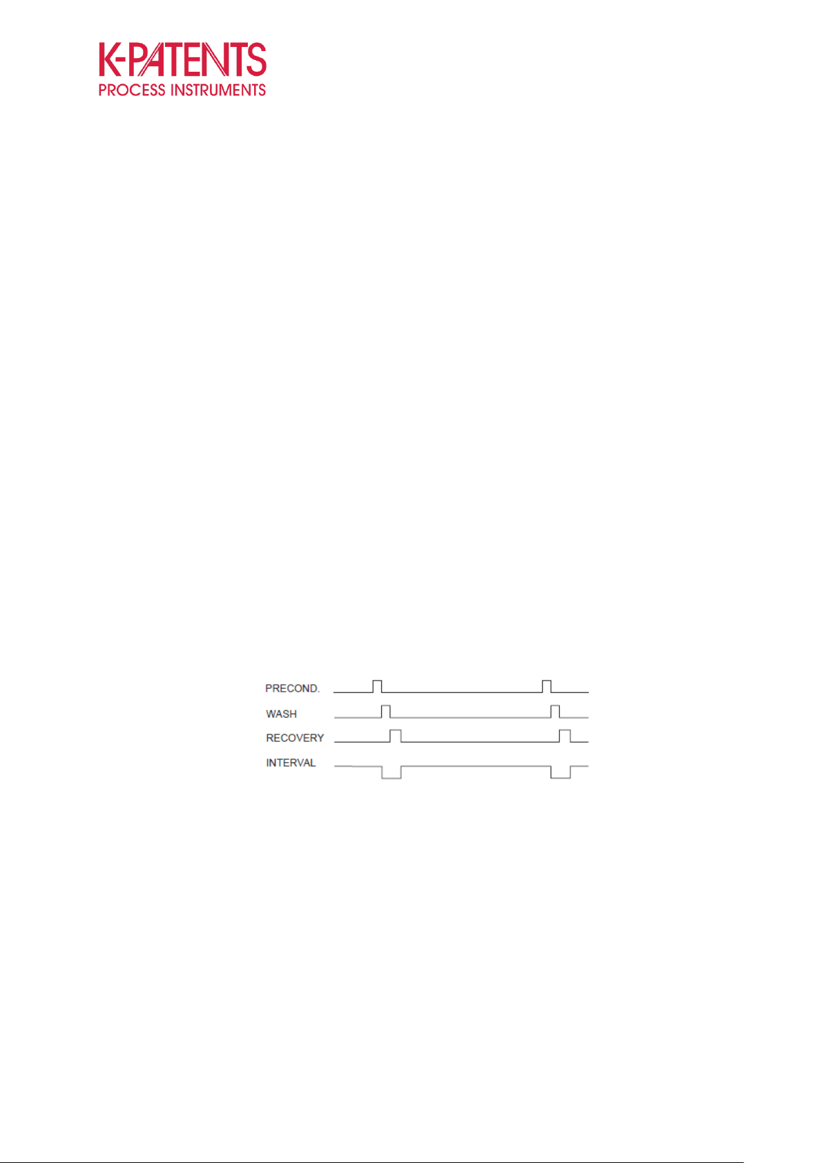
Preconditioning time: This function activates “Preconditioning relay” always at the beginning of the washing
cycle. It is used to clear condensate from the steam pipes before actual prism wash.
Figure 7 Automatic prism wash cycle
Wash time: Determines the time the wash valve is open. Typical washing times are 3-5 seconds with steam
and 5-15 seconds with water. Longer wash times will decrease the life time of the prism.
Recover time: The mA-output is normally on hold during wash to prevent unnecessary disturbances in the
signal to the DCS. The recovery time determines the duration of mA-output hold after the actual wash.
Preset value is 20 seconds.
Wash interval: The time between two wash cycles. It is recommended to shorten the wash interval than
increase wash time, if there are problems with prism coating. Preset values is 20 minutes.
Empty pipe check: This function prevents unnecessary washing during stoppages, when the pipes are
Page 9

TROUBLESHOOTING GUIDE
FOR PR-23 ALL MODELS
9 (14)
January 9, 2015
K-PATENTS OY Postal Address: P.O.Box 77, FI-01511 Vantaa, Finland Street Address: Elannontie 5, FI-01510 Vantaa, Finland Tel. int.+358 207 291 570
Fax int.+358 207 291 577 info@kpatents.com www.kpatents.com Vat No. FI03035575 Business ID 0303557-5 Registered in Helsinki
empty. Washing when the pipe is empty can by very corrosive to the prism, as there is no counter pressure
in the pipe.
3.1 Wash Recommendations
The other critical part of the wash is the wash medium characteristics, especially the temperature and the
pressure. Below you can find general guidelines for the wash parameters and pressures depending on the
wash medium and nozzle type. It is also recommended that the wash medium temperature should always be
higher than the process medium temperature to avoid any solid formation or crystallization.
Figure 8 Recommended wash pressures and times
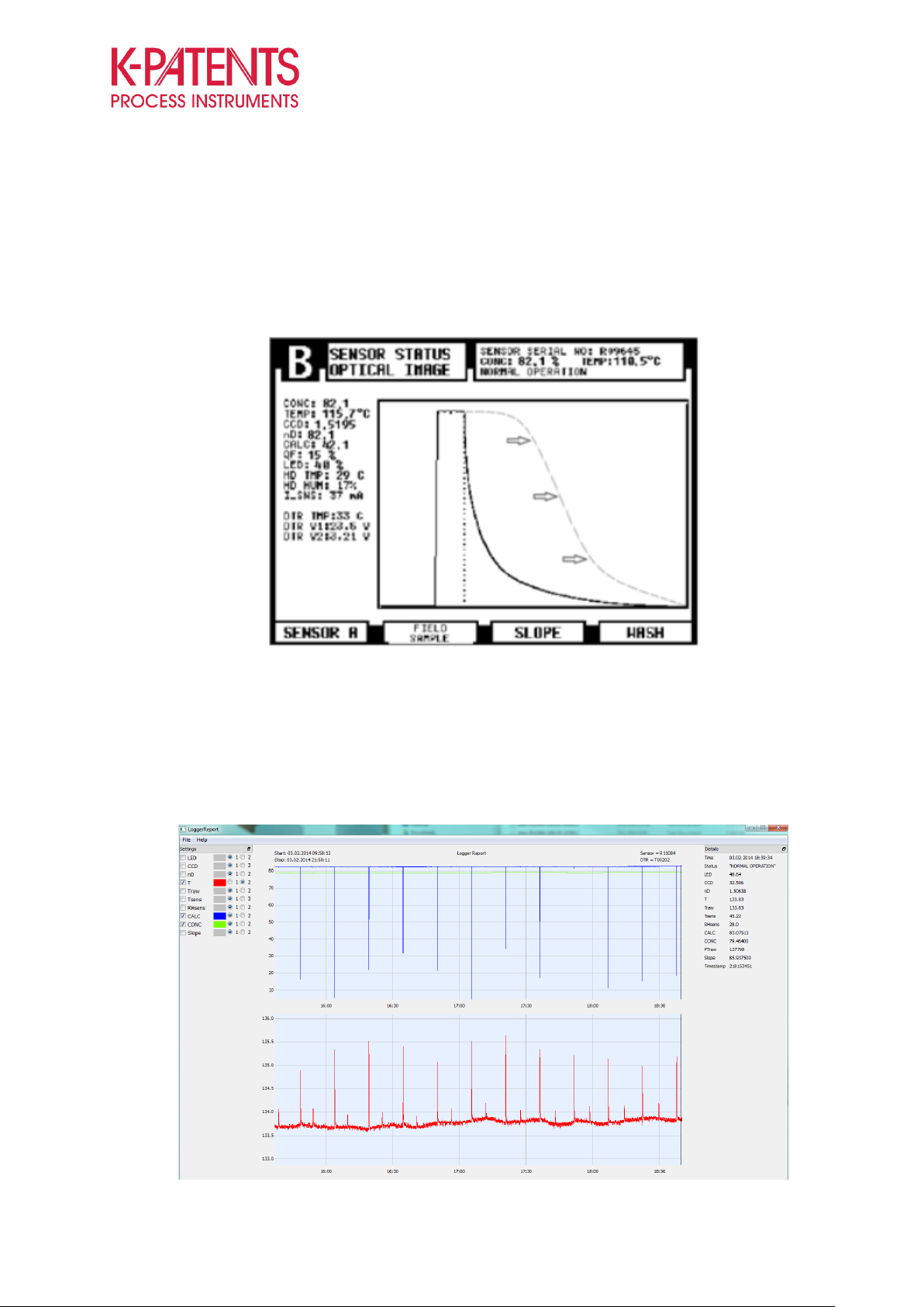
3.2 Successful Wash
As the wash is essential part of the fully functional refractometer, regular testing of the prism wash is
recommended. The manual washing is be activated by pressing MENU 3 SENSOR STATUS MANUAL
WASH. The optical image should change clearly during the wash. Also the temperature reading should
Page 10
TROUBLESHOOTING GUIDE
FOR PR-23 ALL MODELS
10 (14)
January 9, 2015
K-PATENTS OY Postal Address: P.O.Box 77, FI-01511 Vantaa, Finland Street Address: Elannontie 5, FI-01510 Vantaa, Finland Tel. int.+358 207 291 570
Fax int.+358 207 291 577 info@kpatents.com www.kpatents.com Vat No. FI03035575 Business ID 0303557-5 Registered in Helsinki
increase. The visible changes in the curve and the temperature depend on viscosity, steam pressure and
temperature, as well as the software version of the transmitter. If the wash is not reaching the prism, whole
wash system should be examined. There might be blockage in the lines, the wash pressure might be too low
or there might be condensate in the lines because lack of insulation.
Figure 9 Example of successful prism wash
Best way to diagnose and verify successful washing is to log data from the instrument with FC-11. The FC11 logs all the diagnostic values, as well as, all the measurement values. As it can be seen from the picture,
the temperature (red) increases and the CALC (blue) decreases with every wash, whereas the CONC
(green) stays stable all the time. This also reveals intermittent problems in the washing systems.
Figure 10 Data shows clearly if the wash is successful or not.
Page 11

TROUBLESHOOTING GUIDE
FOR PR-23 ALL MODELS
11 (14)
January 9, 2015
K-PATENTS OY Postal Address: P.O.Box 77, FI-01511 Vantaa, Finland Street Address: Elannontie 5, FI-01510 Vantaa, Finland Tel. int.+358 207 291 570
Fax int.+358 207 291 577 info@kpatents.com www.kpatents.com Vat No. FI03035575 Business ID 0303557-5 Registered in Helsinki
4. Typical Faults and Causes
4.1 Description: Measurement is constantly showing 0 concentration or “flat line” in DCS
Cause(s): Error message on the measurement status, such as No optical image, no sensor, short circuit, no
sample etc. During certain error messages the instrument gives “default” mA-output, this is configured to
give 4 mA as preset.
Solution: Troubleshoot the issue indicated by the error message.
4.2 Description: Measurement Status No optical image, low image quality
Cause(s): The CCD-element does not receive enough light to determine the borderline of reflected light vs
shadow on the optical image. Lack of light in 90 % of the cases is caused by coated or eroded prism. Liquid
leakage through the prism gasket also fits this category. Remaining 10 % of the faults are related to the other
optical or electrical faults, such as broken optical fiber or detached flat cable. Severely bad optical images
are generally seen with these error messages.
Solution: Check the functionality of the washing system with manual washes. If that won’t help, clean the
prism with a glassfiber brush and check the optical image. Also check the prism for scratches or marks. The
prism needs to be replaced, if there are any visible marks on the polished surfaces. Possible leakage can be
detected from abnormal temperature readings and increased head humidity. Services can be done only by
K-Patents or a trained service person.
4.3 Description: Spiking concentration outputs
Cause(s): Coating of the prism or prism erosion causes a low quality optical image and unstable
measurement.
Solution: Clean the prism. If the prism is eroded, service accordingly. If the coating is a constant problem,
consider other installation position or additional washing system. Check the functionality of the washing
system, if there already is installed one.
4.4 Description: No connection to the sensor “No Signal”, “No Sensor” or endless “Starting up..”
status
Cause(s): Weak cable connections, faulty sensor processor card, or electrical component failure due to
excessive humidity or temperature inside the sensor. Another potential cause may be a liquid leakage inside
Page 12

TROUBLESHOOTING GUIDE
FOR PR-23 ALL MODELS
12 (14)
January 9, 2015
K-PATENTS OY Postal Address: P.O.Box 77, FI-01511 Vantaa, Finland Street Address: Elannontie 5, FI-01510 Vantaa, Finland Tel. int.+358 207 291 570
Fax int.+358 207 291 577 info@kpatents.com www.kpatents.com Vat No. FI03035575 Business ID 0303557-5 Registered in Helsinki
the sensor.
Solution: The cables should be inspected, and if the problem is not resolved, the sensor processor card
needs to be replaced by K-Patents or a trained service person. If the sensor has leaked liquid, most likely all
the electronics and optics needs to be replaced.
4.5 Description: Inaccurate measurement
Cause(s): These issues are generally related to prism coating, which may result in a constantly increasing
concentration reading. It is also common that the fault is found in the reference measurement method (lab
instrument).
Solution: Clean the prism of the sensor carefully and check the optical image. Proceed with the built-in
verification procedure. If the verification fails, the instrument needs to be inspected by qualified person
before recalibration. If the instrument passes, it is an indication that the issue is related to the process
conditions (too low flow velocity) or ineffective washing.
Figure 11 Verification procedure for checking the calibration
Page 13

TROUBLESHOOTING GUIDE
FOR PR-23 ALL MODELS
13 (14)
January 9, 2015
K-PATENTS OY Postal Address: P.O.Box 77, FI-01511 Vantaa, Finland Street Address: Elannontie 5, FI-01510 Vantaa, Finland Tel. int.+358 207 291 570
Fax int.+358 207 291 577 info@kpatents.com www.kpatents.com Vat No. FI03035575 Business ID 0303557-5 Registered in Helsinki
Weekly check list
Date
CONC
CALC
TEMP
QF
LED
HD HUM
HD TEMP
Wash
OK
SIGNED BY
5. Preventive Maintenance Inspection Plan
Generally, the instrument is maintenance free, but in order to ensure reliable functioning K-Patents
instrument, the following preventive maintenance inspection plan is proposed. The weekly PMI plan includes
only recording of the diagnostic values without any service procedures. The annual plan includes also the
verification procedure and prism check for scaling or wear.
Page 14

TROUBLESHOOTING GUIDE
FOR PR-23 ALL MODELS
14 (14)
January 9, 2015
K-PATENTS OY Postal Address: P.O.Box 77, FI-01511 Vantaa, Finland Street Address: Elannontie 5, FI-01510 Vantaa, Finland Tel. int.+358 207 291 570
Fax int.+358 207 291 577 info@kpatents.com www.kpatents.com Vat No. FI03035575 Business ID 0303557-5 Registered in Helsinki
If you have any questions, please do not hesitate to contact us.
Respectfully,
K-PATENTS
Tel. Int.+358 207 291 570
Fax Int.+358 207 291 577
E-mail: info(at)kpatents.com
 Loading...