

Page 1

INSTRUCTION MANUAL
FOR INLINE REFRACTOMETER
PR-03
WARNING
The process medium may be hot or otherwise hazardous.
Protected by one or more of
the following U.S. patents:
Patent No. 4,571,075
Patent No. 5,563,737
Patent No. 5,009,113
Patent No. 5,617,201
Patent No. 5,309,288
Patent No. 6,067,151
Precautions when removing the sensor from the process line:
Make positively sure that the process line is not under pressure. Open a vent valve to the atmosphere.
For a prism wash system, close a hand valve for the wash medium and disable the wash valve.
Loosen the clamp cautiously, be prepared to tighten again.
Be out of the way of any possible splash and ensure the possibility of escape.
Use shields and protective clothing adequate for the process medium.
Do not rely on avoidance of contact with the process medium.
After removal of the sensor, it may be necessary to mount a blind cover for security reasons.
Document/Revision No. INM-3: Rev. 2/4 Effective: February 15th, 2005
This product manual is delivered to the end user with a K-Patents product.
Information in this manual is subject to change without notice. When the manual is changed,
a revised copy is made available at http://www.kpatents.com/.
Feedback on this manual can be sent by email to manuals@kpatents.com.
THE PASSWORD FOR PR-03 IS 7 8 4 5 1 2 IN PROGRAM VERSIONS 4.0 AND HIGHER.
K-PATENTS OY
Postal address:
P.O. Box 77
FIN-01511 Vantaa, Finland
Tel. + 358-9-825 6640
Fax +358-9-8256 6461
info@kpatents.com
www.kpatents.com
K-PATENTS OY
Street address:
Elannontie 5
FIN-01510 Vantaa, Finland
K-PATENTS, INC.
1804 Centre Point Circle,
Suite 106,
Naperville, IL 60563
Tel. +1-630-955 1545
Fax +1-630-955 1585
Info@kpatents-usa.com
www.kpatents.com
Page 2

Page 3

Table of contents
1 Introduction . . . . . . . . . . . . . . . . . . . . . . . . . . . . . . . . . . . . . . . . . . . . . . . . . . . . . . . . . . . . . . . . . . 1
1.1 PR-03 refractometer models . . . . . . . . . . . . . . . . . . . . . . . . . . . . . . . . . . . . . . . . . . . . . . . 1
1.2 Principle of measurement . . . . . . . . . . . . . . . . . . . . . . . . . . . . . . . . . . . . . . . . . . . . . . . . . . 2
1.3 General safety considerations . . . . . . . . . . . . . . . . . . . . . . . . . . . . . . . . . . . . . . . . . . . . . . 3
1.4 Warranty . . . . . . . . . . . . . . . . . . . . . . . . . . . . . . . . . . . . . . . . . . . . . . . . . . . . . . . . . . . . . . . 3
1.5 Disposal . . . . . . . . . . . . . . . . . . . . . . . . . . . . . . . . . . . . . . . . . . . . . . . . . . . . . . . . . . . . . . . . 3
2 Inline refractometer sensor . . . . . . . . . . . . . . . . . . . . . . . . . . . . . . . . . . . . . . . . . . . . . . . . . . . . 5
2.1 Sensor description . . . . . . . . . . . . . . . . . . . . . . . . . . . . . . . . . . . . . . . . . . . . . . . . . . . . . . . . 5
2.2 Mounting the sensor . . . . . . . . . . . . . . . . . . . . . . . . . . . . . . . . . . . . . . . . . . . . . . . . . . . . . . 6
2.2.1 Choosing sensor mounting location . . . . . . . . . . . . . . . . . . . . . . . . . . . . . . . . . . . . . . . . . 6
2.2.2 Check list for pipe mounting (PR-03-A, PR-03-D, PR-03-M) . . . . . . . . . . . . . . . . . . . . . 7
2.2.3 Check list for mounting in a tank, a vessel or a large pipe (PR-03-P) . . . . . . . . . . . . . . . 8
3 Indicating transmitter (IT-R) . . . . . . . . . . . . . . . . . . . . . . . . . . . . . . . . . . . . . . . . . . . . . . . . . . . 9
3.1 Indicating transmitter description . . . . . . . . . . . . . . . . . . . . . . . . . . . . . . . . . . . . . . . . . . 9
3.2 Mounting Indicating transmitter . . . . . . . . . . . . . . . . . . . . . . . . . . . . . . . . . . . . . . . . . . . 10
3.2.1 Mounting the Interconnecting cable . . . . . . . . . . . . . . . . . . . . . . . . . . . . . . . . . . . . . . . . 10
3.2.2 Electrical connections . . . . . . . . . . . . . . . . . . . . . . . . . . . . . . . . . . . . . . . . . . . . . . . . . . . 11
3.2.2.1 Connecting with sensor . . . . . . . . . . . . . . . . . . . . . . . . . . . . . . . . . . . . . . . . . . . . . . . . 12
3.2.2.2 AC power connection . . . . . . . . . . . . . . . . . . . . . . . . . . . . . . . . . . . . . . . . . . . . . . . . . 12
3.2.2.3 +24 V DC power connection . . . . . . . . . . . . . . . . . . . . . . . . . . . . . . . . . . . . . . . . . . . . 12
3.2.2.4 Current output connection . . . . . . . . . . . . . . . . . . . . . . . . . . . . . . . . . . . . . . . . . . . . . 13
3.2.2.5 Serial bus connections . . . . . . . . . . . . . . . . . . . . . . . . . . . . . . . . . . . . . . . . . . . . . . . . 13
3.2.2.6 Input switch connections . . . . . . . . . . . . . . . . . . . . . . . . . . . . . . . . . . . . . . . . . . . . . . . 13
3.2.3 Serial output connections: connecting a computer with the IT-R . . . . . . . . . . . . . . . . . 14
3.2.4 Demo mode connection . . . . . . . . . . . . . . . . . . . . . . . . . . . . . . . . . . . . . . . . . . . . . . . . . 15
3.3 Cable signals between IT-R and sensor . . . . . . . . . . . . . . . . . . . . . . . . . . . . . . . . . . . . . . 16
4 Accessory units . . . . . . . . . . . . . . . . . . . . . . . . . . . . . . . . . . . . . . . . . . . . . . . . . . . . . . . . . . . . . 17
4.1 Separate relay units . . . . . . . . . . . . . . . . . . . . . . . . . . . . . . . . . . . . . . . . . . . . . . . . . . . . . . 17
4.1.1 Relay unit description . . . . . . . . . . . . . . . . . . . . . . . . . . . . . . . . . . . . . . . . . . . . . . . . . . . 17
4.1.1.1 Relay unit PR-7080 . . . . . . . . . . . . . . . . . . . . . . . . . . . . . . . . . . . . . . . . . . . . . . . . . . . 18
4.1.1.2 Relay unit -WR . . . . . . . . . . . . . . . . . . . . . . . . . . . . . . . . . . . . . . . . . . . . . . . . . . . . . . 18
4.1.2 Prism wash system description . . . . . . . . . . . . . . . . . . . . . . . . . . . . . . . . . . . . . . . . . . . . 18
4.1.3 Relay unit mounting and connections . . . . . . . . . . . . . . . . . . . . . . . . . . . . . . . . . . . . . . . 18
4.1.3.1 Mounting and connecting Relay unit PR-7080 . . . . . . . . . . . . . . . . . . . . . . . . . . . . . . 18
4.1.3.2 Mounting and connecting Relay unit -WR . . . . . . . . . . . . . . . . . . . . . . . . . . . . . . . . . 20
4.1.4 Mounting and connecting prism wash systems . . . . . . . . . . . . . . . . . . . . . . . . . . . . . . . . 20
4.1.4.1 Recommended wash pressures and times . . . . . . . . . . . . . . . . . . . . . . . . . . . . . . . . . . 20
4.1.4.2 Prism wash nozzles . . . . . . . . . . . . . . . . . . . . . . . . . . . . . . . . . . . . . . . . . . . . . . . . . . . 20
4.1.4.3 Mounting of prism wash systems with steam and water . . . . . . . . . . . . . . . . . . . . . . . 23
4.1.4.4 Mounting of prism wash systems with high pressure water . . . . . . . . . . . . . . . . . . . . 25
4.2 External output unit PR-7090 . . . . . . . . . . . . . . . . . . . . . . . . . . . . . . . . . . . . . . . . . . . . . 26
4.2.1 Description . . . . . . . . . . . . . . . . . . . . . . . . . . . . . . . . . . . . . . . . . . . . . . . . . . . . . . . . . . . 26
4.2.2 External output unit mounting and connections . . . . . . . . . . . . . . . . . . . . . . . . . . . . . . . 26
Page 4

5 Startup, configuration and calibration adjustment . . . . . . . . . . . . . . . . . . . . . . . . . . . . . . 29
5.1 Startup . . . . . . . . . . . . . . . . . . . . . . . . . . . . . . . . . . . . . . . . . . . . . . . . . . . . . . . . . . . . . . . . 29
5.2 System check . . . . . . . . . . . . . . . . . . . . . . . . . . . . . . . . . . . . . . . . . . . . . . . . . . . . . . . . . . . 29
5.2.1 Checking accessory units . . . . . . . . . . . . . . . . . . . . . . . . . . . . . . . . . . . . . . . . . . . . . . . . 30
5.2.2 Testing prism wash . . . . . . . . . . . . . . . . . . . . . . . . . . . . . . . . . . . . . . . . . . . . . . . . . . . . . 30
5.3 Using Indicating transmitter . . . . . . . . . . . . . . . . . . . . . . . . . . . . . . . . . . . . . . . . . . . . . . 31
5.3.1 Keyboard functions . . . . . . . . . . . . . . . . . . . . . . . . . . . . . . . . . . . . . . . . . . . . . . . . . . . . . 31
5.4 Soft key Display: Getting information on the process
and the settings . . . . . . . . . . . . . . . . . . . . . . . . . . . . . . . . . . . . . . . . . . . . . . . . . . . . . . . . . 32
5.4.1 Viewing the Optical image . . . . . . . . . . . . . . . . . . . . . . . . . . . . . . . . . . . . . . . . . . . . . . . 33
5.4.2 Viewing System configuration . . . . . . . . . . . . . . . . . . . . . . . . . . . . . . . . . . . . . . . . . . . . 33
5.4.3 Checking conditions inside sensor head . . . . . . . . . . . . . . . . . . . . . . . . . . . . . . . . . . . . . 33
5.5 Soft key Calibrate: Viewing and changing system settings . . . . . . . . . . . . . . . . . . . 34
5.5.1 Viewing Optical image and raw data . . . . . . . . . . . . . . . . . . . . . . . . . . . . . . . . . . . . . . . 34
5.5.2 Raw data explanations . . . . . . . . . . . . . . . . . . . . . . . . . . . . . . . . . . . . . . . . . . . . . . . . . . . 34
5.5.3 Viewing Scaled image . . . . . . . . . . . . . . . . . . . . . . . . . . . . . . . . . . . . . . . . . . . . . . . . . . . 35
5.5.4 Viewing slope . . . . . . . . . . . . . . . . . . . . . . . . . . . . . . . . . . . . . . . . . . . . . . . . . . . . . . . . . 35
5.5.5 Viewing Image diagnostics . . . . . . . . . . . . . . . . . . . . . . . . . . . . . . . . . . . . . . . . . . . . . . . 36
5.6 Configuring input switches . . . . . . . . . . . . . . . . . . . . . . . . . . . . . . . . . . . . . . . . . . . . . . . . 36
5.7 Configuring relays . . . . . . . . . . . . . . . . . . . . . . . . . . . . . . . . . . . . . . . . . . . . . . . . . . . . . . . 37
5.8 Configuring external output unit . . . . . . . . . . . . . . . . . . . . . . . . . . . . . . . . . . . . . . . . . . . 39
5.9 Configuring automatic prism wash . . . . . . . . . . . . . . . . . . . . . . . . . . . . . . . . . . . . . . . . . 39
5.9.1 Timed wash . . . . . . . . . . . . . . . . . . . . . . . . . . . . . . . . . . . . . . . . . . . . . . . . . . . . . . . . . . . 40
5.9.2 Smart wash . . . . . . . . . . . . . . . . . . . . . . . . . . . . . . . . . . . . . . . . . . . . . . . . . . . . . . . . . . . 40
5.9.3 Preventing automatic wash . . . . . . . . . . . . . . . . . . . . . . . . . . . . . . . . . . . . . . . . . . . . . . . 41
5.9.4 Prism wash check . . . . . . . . . . . . . . . . . . . . . . . . . . . . . . . . . . . . . . . . . . . . . . . . . . . . . . 41
5.10 Adjusting concentration calibration . . . . . . . . . . . . . . . . . . . . . . . . . . . . . . . . . . . . . . . . 43
5.10.1 Checking current calibration . . . . . . . . . . . . . . . . . . . . . . . . . . . . . . . . . . . . . . . . . . . . . . 43
5.10.2 Concentration calibration from keyboard . . . . . . . . . . . . . . . . . . . . . . . . . . . . . . . . . . . . 43
5.10.3 Output current range selection . . . . . . . . . . . . . . . . . . . . . . . . . . . . . . . . . . . . . . . . . . . . 44
5.10.4 Temperature calibration . . . . . . . . . . . . . . . . . . . . . . . . . . . . . . . . . . . . . . . . . . . . . . . . . 44
5.10.5 Adjusting damping time . . . . . . . . . . . . . . . . . . . . . . . . . . . . . . . . . . . . . . . . . . . . . . . . . 44
5.10.6 Field calibration . . . . . . . . . . . . . . . . . . . . . . . . . . . . . . . . . . . . . . . . . . . . . . . . . . . . . . . 45
5.10.7 Bench calibration . . . . . . . . . . . . . . . . . . . . . . . . . . . . . . . . . . . . . . . . . . . . . . . . . . . . . . 46
6 Regular maintenance . . . . . . . . . . . . . . . . . . . . . . . . . . . . . . . . . . . . . . . . . . . . . . . . . . . . . . . . 47
6.1 Checking the sensor moisture . . . . . . . . . . . . . . . . . . . . . . . . . . . . . . . . . . . . . . . . . . . . . 47
6.2 Checking and replacing prism or prism gaskets . . . . . . . . . . . . . . . . . . . . . . . . . . . . . . 47
6.3 Disassembling and assembling a standard length sensor . . . . . . . . . . . . . . . . . . . . . . . 48
6.3.1 Disassembling the sensor . . . . . . . . . . . . . . . . . . . . . . . . . . . . . . . . . . . . . . . . . . . . . . . . 48
6.3.2 Replacing the prism and prism gaskets . . . . . . . . . . . . . . . . . . . . . . . . . . . . . . . . . . . . . . 49
6.3.3 Assembling the sensor . . . . . . . . . . . . . . . . . . . . . . . . . . . . . . . . . . . . . . . . . . . . . . . . . . 50
6.4 Disassembling and assembling a probe sensor . . . . . . . . . . . . . . . . . . . . . . . . . . . . . . . . 51
6.4.1 Disassembling the probe sensor . . . . . . . . . . . . . . . . . . . . . . . . . . . . . . . . . . . . . . . . . . . 51
6.4.2 Replacing the prism and prism gaskets . . . . . . . . . . . . . . . . . . . . . . . . . . . . . . . . . . . . . . 52
6.4.3 Assembling the probe sensor . . . . . . . . . . . . . . . . . . . . . . . . . . . . . . . . . . . . . . . . . . . . . 54
Page 5

7 Troubleshooting and correcting problems . . . . . . . . . . . . . . . . . . . . . . . . . . . . . . . . . . . . . 55
7.1 Troubleshooting Indicating transmitter . . . . . . . . . . . . . . . . . . . . . . . . . . . . . . . . . . . . . 55
7.2 Troubleshooting sensor . . . . . . . . . . . . . . . . . . . . . . . . . . . . . . . . . . . . . . . . . . . . . . . . . . . 55
7.2.1 LED value . . . . . . . . . . . . . . . . . . . . . . . . . . . . . . . . . . . . . . . . . . . . . . . . . . . . . . . . . . . . 55
7.2.2 Sensor temperature and humidity . . . . . . . . . . . . . . . . . . . . . . . . . . . . . . . . . . . . . . . . . . 56
7.2.3 Slope value . . . . . . . . . . . . . . . . . . . . . . . . . . . . . . . . . . . . . . . . . . . . . . . . . . . . . . . . . . . 56
7.2.4 Image diagnostics . . . . . . . . . . . . . . . . . . . . . . . . . . . . . . . . . . . . . . . . . . . . . . . . . . . . . . 57
8 Sensor specifications and
other sensor information . . . . . . . . . . . . . . . . . . . . . . . . . . . . . . . . . . . . . . . . . . . . . . . . . . . . . 59
8.1 Sensor labels . . . . . . . . . . . . . . . . . . . . . . . . . . . . . . . . . . . . . . . . . . . . . . . . . . . . . . . . . . . 59
8.2 Sensor compatibility . . . . . . . . . . . . . . . . . . . . . . . . . . . . . . . . . . . . . . . . . . . . . . . . . . . . . 59
8.3 Sanitary refractometer PR-03-A . . . . . . . . . . . . . . . . . . . . . . . . . . . . . . . . . . . . . . . . . . . 59
8.3.1 PR-03-A sensor model code . . . . . . . . . . . . . . . . . . . . . . . . . . . . . . . . . . . . . . . . . . . . . . 60
8.3.2 PR-03-A mounting hardware model code . . . . . . . . . . . . . . . . . . . . . . . . . . . . . . . . . . . . 60
8.3.3 PR-03-A specifications . . . . . . . . . . . . . . . . . . . . . . . . . . . . . . . . . . . . . . . . . . . . . . . . . . 62
8.3.4 PR-03-A parts lists . . . . . . . . . . . . . . . . . . . . . . . . . . . . . . . . . . . . . . . . . . . . . . . . . . . . . 63
8.3.5 PR-03-A mounting specifics . . . . . . . . . . . . . . . . . . . . . . . . . . . . . . . . . . . . . . . . . . . . . . 65
8.4 Probe refractometer PR-03-P . . . . . . . . . . . . . . . . . . . . . . . . . . . . . . . . . . . . . . . . . . . . . 68
8.4.1 PR-03-P sensor model code . . . . . . . . . . . . . . . . . . . . . . . . . . . . . . . . . . . . . . . . . . . . . . 68
8.4.2 PR-03-P mounting hardware model code . . . . . . . . . . . . . . . . . . . . . . . . . . . . . . . . . . . . 68
8.4.3 PR-03-P specifications . . . . . . . . . . . . . . . . . . . . . . . . . . . . . . . . . . . . . . . . . . . . . . . . . . 69
8.4.4 PR-03-P parts lists . . . . . . . . . . . . . . . . . . . . . . . . . . . . . . . . . . . . . . . . . . . . . . . . . . . . . . 70
8.4.5 PR-03-P mounting specifics . . . . . . . . . . . . . . . . . . . . . . . . . . . . . . . . . . . . . . . . . . . . . . 72
8.4.6 PR-03-P programming specifics . . . . . . . . . . . . . . . . . . . . . . . . . . . . . . . . . . . . . . . . . . . 74
8.5 Compact process refractometer PR-03-D . . . . . . . . . . . . . . . . . . . . . . . . . . . . . . . . . . . . 75
8.5.1 PR-03-D sensor model code . . . . . . . . . . . . . . . . . . . . . . . . . . . . . . . . . . . . . . . . . . . . . . 75
8.5.2 PR-03-D mounting hardware model code . . . . . . . . . . . . . . . . . . . . . . . . . . . . . . . . . . . . 75
8.5.3 PR-03-D specifications . . . . . . . . . . . . . . . . . . . . . . . . . . . . . . . . . . . . . . . . . . . . . . . . . . 76
8.5.4 PR-03-D parts lists . . . . . . . . . . . . . . . . . . . . . . . . . . . . . . . . . . . . . . . . . . . . . . . . . . . . . 77
8.5.5 PR-03-D mounting specifics . . . . . . . . . . . . . . . . . . . . . . . . . . . . . . . . . . . . . . . . . . . . . . 79
8.6 Process refractometer PR-03-M . . . . . . . . . . . . . . . . . . . . . . . . . . . . . . . . . . . . . . . . . . . 81
8.6.1 PR-03-M sensor model code . . . . . . . . . . . . . . . . . . . . . . . . . . . . . . . . . . . . . . . . . . . . . . 81
8.6.2 PR-03-M specifications . . . . . . . . . . . . . . . . . . . . . . . . . . . . . . . . . . . . . . . . . . . . . . . . . . 82
8.6.3 PR-03-M parts lists . . . . . . . . . . . . . . . . . . . . . . . . . . . . . . . . . . . . . . . . . . . . . . . . . . . . . 83
8.6.4 PR-03-M mounting specifics . . . . . . . . . . . . . . . . . . . . . . . . . . . . . . . . . . . . . . . . . . . . . . 85
8.7 Valve body refractometer PR-03-W . . . . . . . . . . . . . . . . . . . . . . . . . . . . . . . . . . . . . . . . . 85
8.7.1 PR-03-W sensor model code . . . . . . . . . . . . . . . . . . . . . . . . . . . . . . . . . . . . . . . . . . . . . . 86
8.7.2 PR-03-W specifications . . . . . . . . . . . . . . . . . . . . . . . . . . . . . . . . . . . . . . . . . . . . . . . . . . 87
8.7.3 PR-03-W parts lists . . . . . . . . . . . . . . . . . . . . . . . . . . . . . . . . . . . . . . . . . . . . . . . . . . . . . 88
8.7.4 PR-03-W mounting specifics . . . . . . . . . . . . . . . . . . . . . . . . . . . . . . . . . . . . . . . . . . . . . . 89
Page 6

9 Indicating transmitter specifications . . . . . . . . . . . . . . . . . . . . . . . . . . . . . . . . . . . . . . . . . . 91
9.1 IT-R label . . . . . . . . . . . . . . . . . . . . . . . . . . . . . . . . . . . . . . . . . . . . . . . . . . . . . . . . . . . . . . 91
9.2 IT-R compatibility . . . . . . . . . . . . . . . . . . . . . . . . . . . . . . . . . . . . . . . . . . . . . . . . . . . . . . . 91
9.2.1 Upgrading IT-R program version . . . . . . . . . . . . . . . . . . . . . . . . . . . . . . . . . . . . . . . . . . 91
9.3 Model code . . . . . . . . . . . . . . . . . . . . . . . . . . . . . . . . . . . . . . . . . . . . . . . . . . . . . . . . . . . . . 92
9.3.1 IT-R model code . . . . . . . . . . . . . . . . . . . . . . . . . . . . . . . . . . . . . . . . . . . . . . . . . . . . . . . 92
9.3.2 Interconnecting cable model code . . . . . . . . . . . . . . . . . . . . . . . . . . . . . . . . . . . . . . . . . 93
9.4 IT-R Specifications . . . . . . . . . . . . . . . . . . . . . . . . . . . . . . . . . . . . . . . . . . . . . . . . . . . . . . 93
9.4.1 Fuses . . . . . . . . . . . . . . . . . . . . . . . . . . . . . . . . . . . . . . . . . . . . . . . . . . . . . . . . . . . . . . . . 93
9.4.2 Serial output specifications . . . . . . . . . . . . . . . . . . . . . . . . . . . . . . . . . . . . . . . . . . . . . . . 94
9.4.3 Password . . . . . . . . . . . . . . . . . . . . . . . . . . . . . . . . . . . . . . . . . . . . . . . . . . . . . . . . . . . . . 94
9.5 IT-R Parts list . . . . . . . . . . . . . . . . . . . . . . . . . . . . . . . . . . . . . . . . . . . . . . . . . . . . . . . . . . 95
9.6 Command selection tree . . . . . . . . . . . . . . . . . . . . . . . . . . . . . . . . . . . . . . . . . . . . . . . . . . 96
9.7 Display messages . . . . . . . . . . . . . . . . . . . . . . . . . . . . . . . . . . . . . . . . . . . . . . . . . . . . . . . . 97
10 PR-03 process refractometers in potentially explosive atmosphere . . . . . . . . . . . . . 101
10.1 Equipment . . . . . . . . . . . . . . . . . . . . . . . . . . . . . . . . . . . . . . . . . . . . . . . . . . . . . . . . . . . . 101
10.2 Installation . . . . . . . . . . . . . . . . . . . . . . . . . . . . . . . . . . . . . . . . . . . . . . . . . . . . . . . . . . . . 102
10.3 PR-03-...-AX parts list: differences to standard sensors . . . . . . . . . . . . . . . . . . . . . . . 103
A Glossary and Abbreviations . . . . . . . . . . . . . . . . . . . . . . . . . . . . . . . . . . . . . . . . . . . . . . . . . 105
B Information about Delivery data sheet (DDS) . . . . . . . . . . . . . . . . . . . . . . . . . . . . . . . . . . 107
C K-Patents inline refractometer calibration data report . . . . . . . . . . . . . . . . . . . . . . . . . 109
D Instrument verification ISO 9000 . . . . . . . . . . . . . . . . . . . . . . . . . . . . . . . . . . . . . . . . . . . . . 111
Index . . . . . . . . . . . . . . . . . . . . . . . . . . . . . . . . . . . . . . . . . . . . . . . . . . . . . . . . . . . . . . . . . . . . . . . . . . 115
Page 7
1 Introduction 1
C: Indicating Transmitter
ABCD
7
4
1
0
8
5
2
.
9
6
3
-
ENTER RESET
K-PATENTS
PROCESSINSTRUMENTS
B: Interconnecting cable
A: Sensor
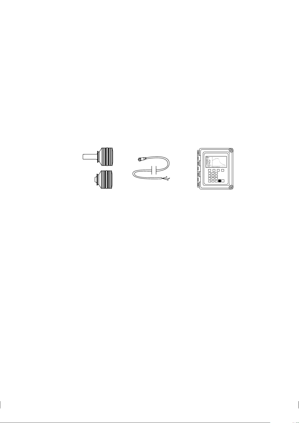
1 Introduction
The K-Patents inline refractometer is an instrument for measuring liquid concentration in the process line.
The measurement is based on the refraction of light in the process medium, an accurate and safe way of
measuring liquid concentration.
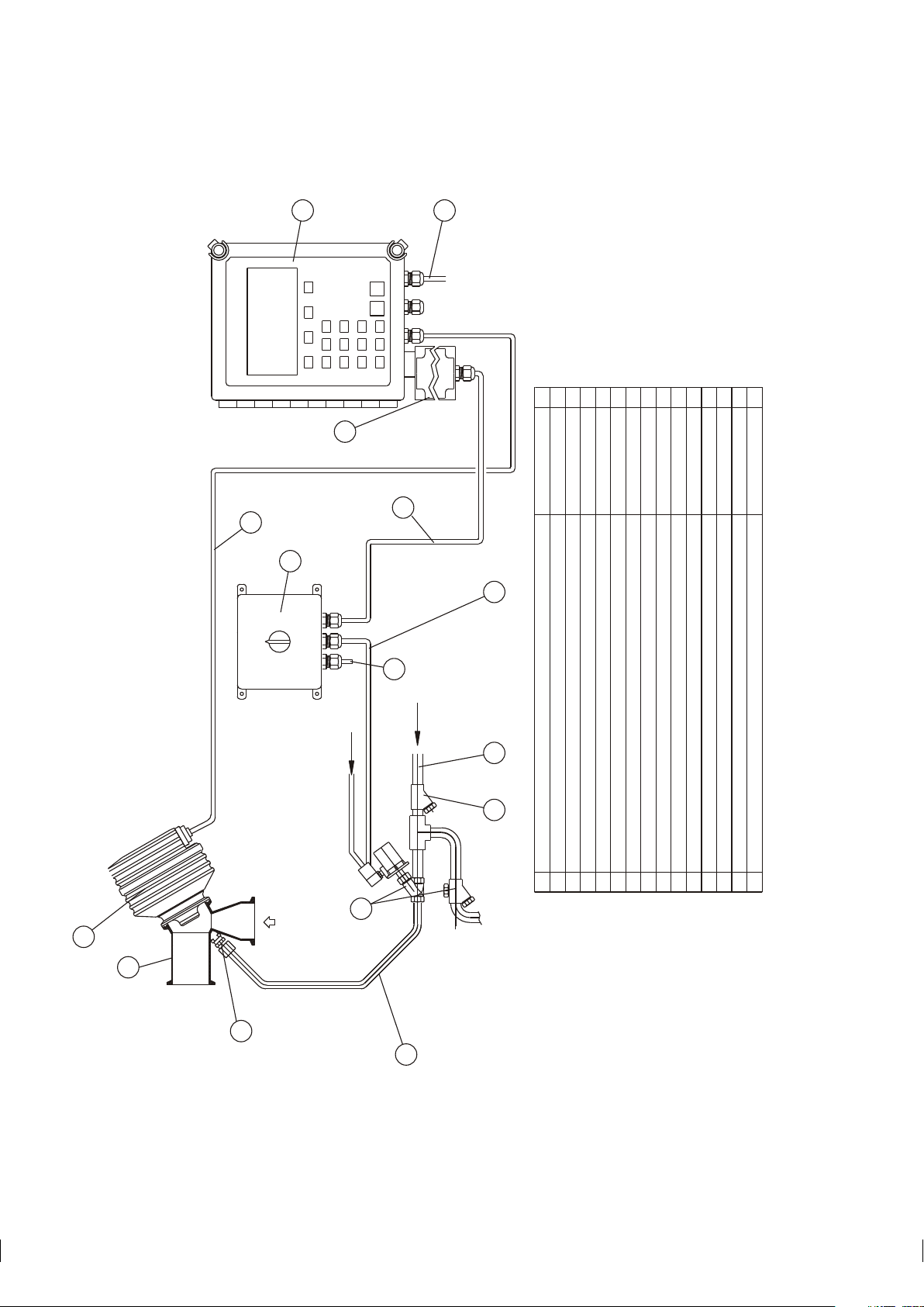
The refractometer sensor (A in figure Figure 1.1), mounted inline, sends a ray of light into the process
medium and measures the angle in which the light is refracted back from the liquid. This information is
then sent via the interconnecting cable (B) to the Indicating transmitter (C). The Indicating transmitter (ITR) then calculates the concentration of the process liquid based on the refractive angle, taking temperature
and pre-defined process conditions into account. The output the IT-R provides is a 4 to 20 mA DC output
signal proportional to process solution concentration, but a serial output is also available as a standard.
Figure 1.1 Refractometer equipment.
1.1 PR-03 refractometer models
The basic system of a sensor and an Indicating transmitter connected with a cable is the same in all PR-03
Inline refractometer models. However, there are different sensor models, each adapted for different process
requirements.
The Sanitary refractometer sensor PR-03-A and the Probe refractometer sensor PR-03-P both meet
the 3-A Sanitary Standard requirements. The model PR-03-A is an all-purpose instrument for a variety of
alimentary processes while the PR-03-P is especially designed for cookers and tanks and can even be used
in combination with a scraper in alimentary as well as other processes.
The Compact process refractometer PR-03-D is an all-round instrument for measuring the concentration
of a wide range of chemicals and liquids. The Process refractometer PR-03-M is built for chemically
aggressive solutions and ultra-pure processes, all of its wetted parts are made of non-metallic materials.
The Valve body refractometer PR-03-W is very similar to the Process refractometer PR-03-M, but the
special valve body makes it possibly to use it in large-scale production and large pipelines.
The model number of a refractometer system is displayed on the serial number label on the sensor head
(see Chapter 8, “Sensor specifications and other sensor information”). The serial numbers on the sensor
identification label (see Chapter 8) and the transmitter’s identification label (see Chapter 9) should always
match.
Page 8
2 PR-03 instruction manual
L
P
MM
S
A C B
BB
C
C
A
A
Low concentration High concentration
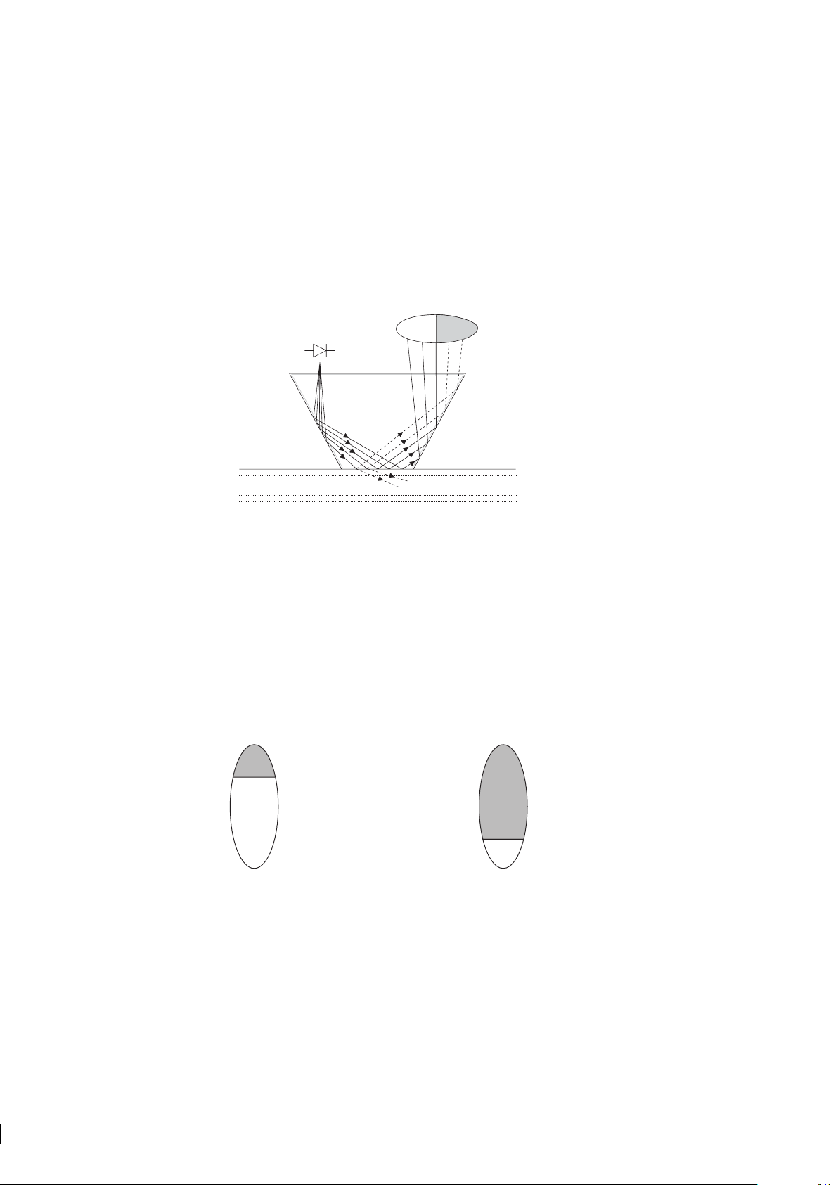
1.2 Principle of measurement
The K-Patents inline refractometer sensor determines the refractive index (R.I.) of the process solution by
measuring the critical angle of refraction. Light from a light source ((L) in Figure 1.2) in the sensor is
directed to this interface. Two of the prism surfaces (M) are total-reflecting mirrors bending the light rays
that thus meet the inter face at different angles.
Figure 1.2 Refractometer principle
The reflected rays of light form an image (ACB), where (C) is the position of the critical angle ray. The
rays at (A) are totally reflected at the process interface, the rays at (B) are partially reflected and partially
refracted into the process solution. In this way the optical image is divided into a light area (A) and a dark
area (B). The position of the borderline (C) between the areas shows the value of the critical angle and thus
of the refractive index (R.I.) of the process solution.
The R.I. changes with the process solution temperature and concentration. In higher temperatures the R.I. is
smaller than in room temperature (standard R.I. 25◦C). When the concentration changes, the R.I. normally
increases when the concentration increases. From this follows that the optical image changes with the
process solution concentration as shown in Figure 1.3. The color of the solution, gas bubbles or undissolved
particles do not affect the result.
Figure 1.3 Optical images
The optical image thus achieved is converted to an electric signal by a digitizer inside the sensor. This
electric signal is then sent via an interconnecting cable to the Indicating transmitter’s microprocessor for
further processing, displaying and transmitting.
Page 9

1 Introduction 3
1.3 General safety considerations
The process medium may be hot or otherwise hazardous. Use shields and protective clothing adequate for
the process medium - do not rely on avoidance of contact with the process medium.
Precautions when removing the sensor from the process line:
• Make positively sure that the process line is not under pressure. Open a vent valve to the atmosphere.
• For a prism wash system, close a hand valve for the wash medium and disable the wash valve.
• Loosen the clamp cautiously, be prepared to tighten again.
• Be out of the way of any possible splash and ensure t he possibility of escape.
• After removal of the sensor, it may be necessary to mount a blind cover for security reasons.
1.4 Warranty
K-Patents warrants that all products made by K-Patents shall be free of defects in material and workmanship.
K-Patents agrees to either replace or repair free of charge, any such product or part thereof which shall be
returned to the nearest authorized K-Patents repair facility within two (2) years from the date of delivery.
Before returning a defective product for service or replacement, please contact K-Patents or your nearest
K-Patents representative (see http://www.kpatents.com/ for contact information). For the health and safety
of personnel handling your return, clean the instrument, especially the parts that have been in contact with
the process liquid, before packing it. Ship the cleaned instrument to the address given to you.
1.5 Disposal
When disposing of an obsolete instrument or any parts of an instrument, please observe the local and national requirements for the disposal of electrical and electronic equipment. The steel Indicating transmitter
enclosure and the aluminium or stainless steel sensor housing can be recycled with other metallic waste of
the same type.
Page 10

4 PR-03 instruction manual
Page 11
2 Inline refractometer sensor 5
2 Inline refractometer sensor
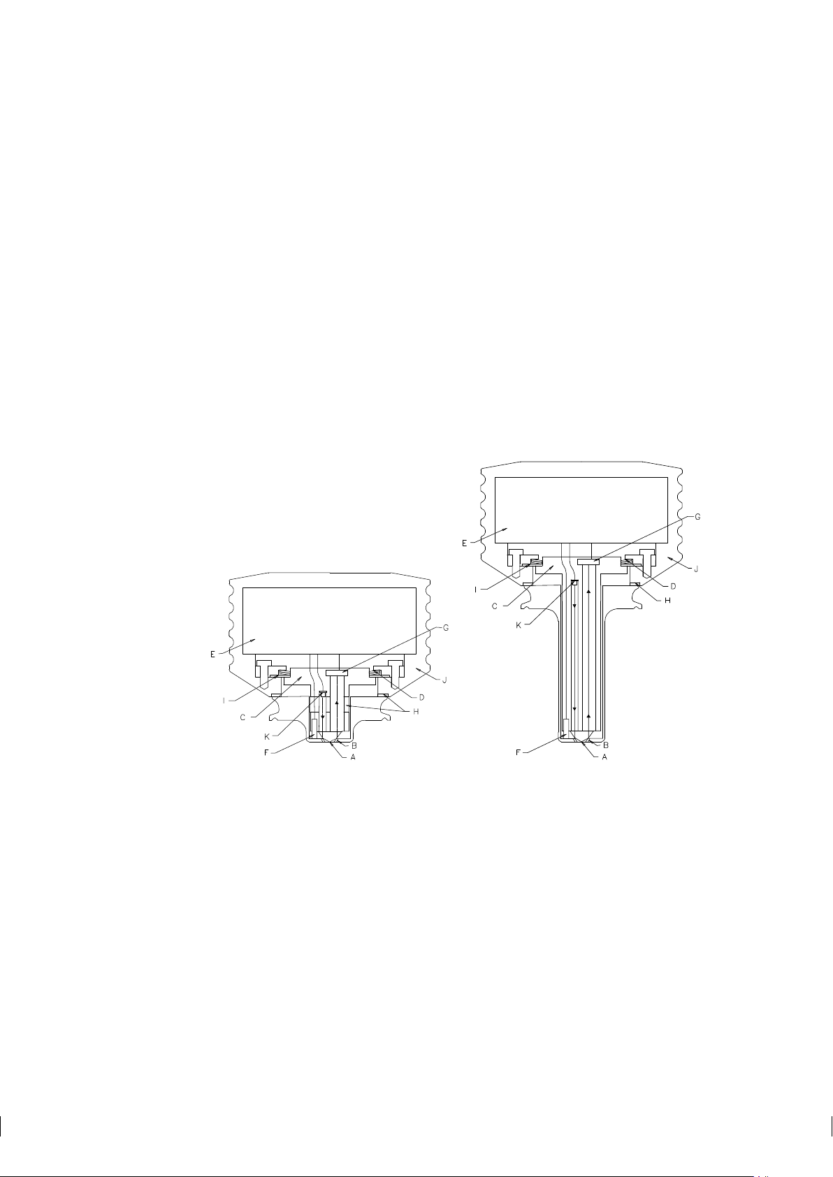
2.1 Sensor description
Figure 2.1 below shows cutaway pictures of two refractometer sensors. These sensors are otherwise similar in structure, but the sensor on the right has a longer probe. The short probe is the more common
refractometer sensor design, only the Probe Refractometer PR-03-P is built like the sensor to the right in
Figure 2.1.
In the sensor the measurement prism (A) is flush mounted to the surface of the probe tip. The prism is fixed
to the analyzer module (C) which is spring-loaded (D) against the prism gasket (B). The light source is a
light emitting diode (K). The digital image detector (G) is a CCD element consisting of 1024 photocells
in a row integrated on one chip. The image sensor (G) is protected from the process heat by two isolating
parts (H). Excess heat is transferred by a heat conductor (I) to the air cooled sensor cover (J). For automatic
temperature compensation, the sensor tip contains a process temperature probe (F), Pt-100.
Figure 2.1 PR-03 sensor structure
The image detector output is a pulse train as shown in Figure 2.2. The number of high pulses corresponds
to the position of the shadow edge in the optical image and is thus a direct measure of t he critical angle.
The image digitizer (E) transforms this pulse train to a serial digital signal. This serial signal transmits to
the Indicating transmitter a package containing temperature data and a complete description of the optical
image.
Note: K-Patents in-line refractometer PR-03 is using a 1024-pixel CCD-element. To keep the supporting
transmitter software compatible for all K-Patents refractometers, the TEST value (= number of photocells
at the light side) is scaled to the range 8-248. That is, for PR-03 the number of high pulses (Figure 2.2) is
divided by four.
Page 12

6 PR-03 instruction manual
a: optical image
b: detector window and the photocells
c: pulse train from detector
TIME
V
Figure 2.2 Image detector system
Note: In the Probe refractometer PR-03-P the image is inverted by the optics. That is, the shadow comes
in from the left. The image is inverted back to normal (as in Figure 2.2) by the indicating transmitter before
any further processing.
2.2 Mounting the sensor
The sensor mounting location should be chosen with care to ensure that you get reliable readings from
your process. Some basic rules, described in this section, apply to all sensor models. The model specific
instructions can be found in Chapter 8.
2.2.1 Choosing sensor mounting location
A K-Patents in-line refractometer sensor can be located either indoors or outdoors in most climates. However, if the sensor is located outdoors, some basic protection against direct exposure to sunlight and rain
should be provided. Special care should be taken if the pipe wall is translucent (e.g. of fiberglass), because
light from outside reaching the prism will disturb the measurement.
The mounting location needs to be such that sediments or gas bubbles cannot accumulate by the sensor.
Good flow velocity is essential in keeping the prism clean.
Always check that the sensor head is kept cool enough, the sensor head should not be too hot to keep a hand
on. The red sensor cover should not be exposed to high temperature radiation. Normally, draft and natural
convection provide sufficient air cooling if the air gets to flow freely around the sensor head.
Additional cooling is necessary when the ambient temperature is higher than 45◦C (113◦F) or when the
process temperature is above 110◦C (230◦F) and the ambient temperature is above 35◦C (95◦F). The aircooling is improved by blowing pressurized air against the red sensor cover. The pressurized air can be
supplied by the ventilation system. If no air is available it is also possible to wind a copper coil for cooling
water around the sensor head cover.
Page 13
2 Inline refractometer sensor 7
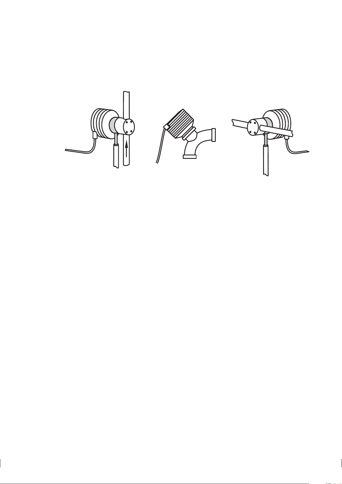
Important: Always mount the sensor so that the cable plug socket on the sensor head points downwards,
i.e. so that when the interconnecting cable is plugged into the sensor, the cable hangs down.
Figure 2.3 Refractometer cable plug direction
2.2.2 Check list for pipe mounting (PR-03-A, PR-03-D, PR-03-M)
1. If the process pipe diameter varies, select the position with the smallest diameter (and accordingly
highest velocity). Then the prism keeps better clean. If the pipe is coned up after a pump, valve or
magnetic flow meter, then add a length of straight pipe before the coning up and mount the refractometer
there.
2. If the refractometer is used in a feed-back control loop, make the time lag short. E.g. when a dilution
valve is controlled, mount the refractometer as near the dilution point as possible.
3. If the temperature varies along the process pipe, select the position with the highest temperature. Then
the risk of prism coating is minimized, because higher temperature means higher solubility and also
lower viscosity.
4. Often the position with the highest pressure (= after pump + before valve) has favorable flow conditions
without sedimentation or air trapping risks.
5. The sensor should be conveniently accessible for service.
Important: If the process pipe vibrates, support the pipe. A vibrating pipe might damage the inline sensor
mounted on it.
Page 14

8 PR-03 instruction manual
2.2.3 Check list for mounting in a tank, a vessel or a large pipe (PR-03-P)
A Probe sensor PR-03-P can be inserted with a sanitary clamp into tanks and vessels which either don’t
have a scraper or where the mixer doesn’t touch the vessel wall. A Probe sensor can also be flush mounted
in a cooker where the scraper touches the wall.
1. Both the inserted and the flush mounted Probe sensor are mounted on the vessel wall with the cable
socket downwards.
2. The inserted probe sensor is mounted close to a stirrer to ensure representative sample of the process
liquid and to keep the prism clean.
3. The sensor should be conveniently accessible for service.
Page 15
3 Indicating transmitter (IT-R) 9
ABCD
7
4
1
0
8
5
2
.
9
6
3
-
ENTER RESET
K-PATENTS
PROCESSINSTRUMENTS
Raw data
Curve fitted to the data
10
20
30
40
50
60
70
1.35 1.40 1.45
R.I.
BRIX
3 Indicating transmitter (IT-R)
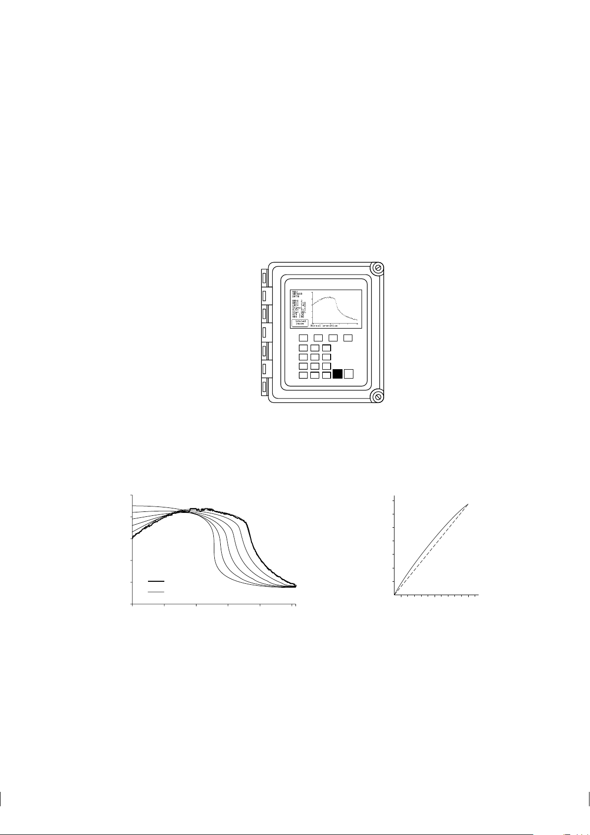
3.1 Indicating transmitter description
The indicating transmitter (abbr. IT-R) is a small, specialized computer designed to process data received
from the sensor. The Indicating transmitter enclosure (see Figure 3.1) contains a front panel with a Liquid
Crystal Display (LCD) and a keyboard. The IT-R’s microprocessor system and the power supply are hidden
under the front panel that swings open for service. Knockout padlock provisions for locks are included in
the enclosure’s both cover latches to prevent unauthorized access.
Figure 3.1 The Indicating transmitter enclosure
The IT-R receives from the sensor data that describes the optical image and gives the process temperature.
It then displays the optical image (Figure 1.3) and implements an image analyzing algorithm (Figure 3.2),
which identifies the exact position of the shadow edge (Figure 2.2). Finally, the microprocessor system
linearizes the concentration reading (example in Figure 3.3), and performs an automatic temperature compensation.
Figure 3.2 Image analyzing algorithm
Figure 3.3 A Brix diagram
The IT-R output signals are a 4-20 mA concentration signal and a serial output signal, RS232 or RS485
alternatively, which enables connections to for example a PC (See Section 3.2.3).
In the IT-R there are also two built-in signal relays on the power supply card. These signal relays can
be configured to any relay function except preconditioning or wash control (see Section 5.7, “Configuring
relays”).
Page 16
10 PR-03 instruction manual
Furthermore, the Indicating transmitter accepts four input switches which can be configured for example to
signal HOLD during external wash or to contain different scale settings each (see Section 5.6, “Configuring
input switches”).
3.2 Mounting Indicating transmitter
The Indicating transmitter should preferably be located in an easily accessible, well lighted and dry area.
The enclosure must not be exposed to rain or direct sunlight. Avoid vibration. Take interconnecting cable
length into consideration when choosing mounting location.
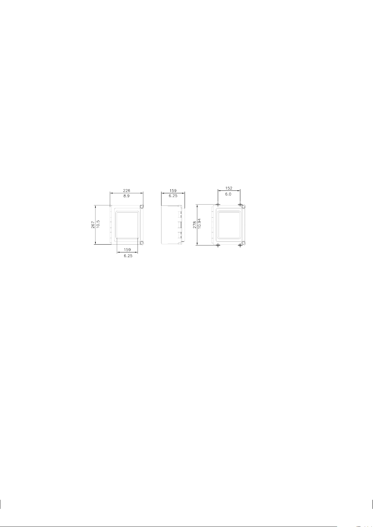
The enclosure is mounted vertically on an upright surface (wall) using four mounting feet, see Figure 3.4.
Important: Do not drill mounting holes in the enclosure as that will affect the protection class of the
enclosure and may expose the electronics of the IT-R.
Figure 3.4 Mounting the Indicating transmitter
Note: The LCD display has an operating temperature range of 0–50
-20–60◦C. If exposed to very low storage temperatures, let the IT-R reach the ambient temperature before
turning it on, as the LCD may not be able to display anything in temperatures below zero.
3.2.1 Mounting the Interconnecting cable
The interconnecting cable PR-8300 is made at the K-Patents factory according to the specifications given
in your order (see Section 9.4). The maximum length of an interconnecting cable is 100 meters (330 feet).
When mounting the cable, check that the ends easily reach the sensor respectively the IT-R.
Warning! Do not try to shorten or lengthen the interconnecting cable! If a new cable is needed for example
!
after the IT-R has been moved further away from the process line, you can order a spare part cable from
K-Patents or your local K-Patents representative.
◦
C and a storage temperature range of
Page 17
3 Indicating transmitter (IT-R) 11
11
POWER
SELECTOR
POWER
CONNECTION
SERIAL CABLE
(pc)
SENSOR
CABLE
ACCESSORY UNIT
(serial bus)
SWITCHES
RELAYS
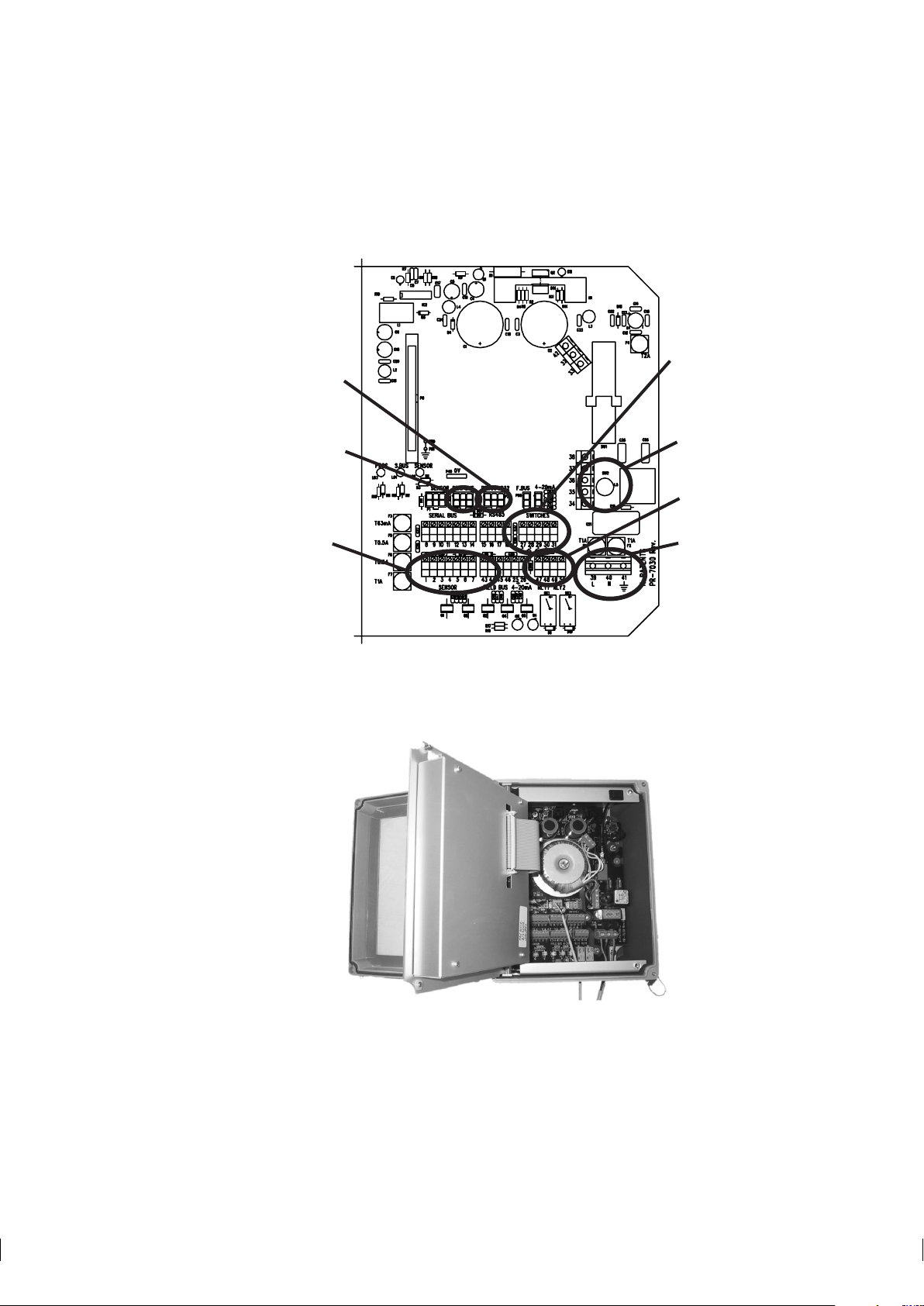
3.2.2 Electrical connections
All the electric terminals of the Indicating transmitter are on the Power supply card (Figure 3.5).
Figure 3.5 Power supply card layout
To access the Power supply card, first open the enclosure cover. Then loosen the two screws on the righthand corners of the front panel and swing open the front panel to see the card.
Figure 3.6 IT-R with opened front panel.
Page 18
12 PR-03 instruction manual
NEUTRAL
LINE
GROUND
3.2.2.1 Connecting with sensor
The sensor end of the interconnecting cable is terminated by a plug. The plug goes into the cable plug
socket on the sensor head. After connecting the cable with the sensor, join the two connector protecting
caps to keep t hem clean inside.
The Indicating transmitter end of the interconnecting cable has leads numbered from 1 to 7 to be connected
to the terminals with the same numbers on the Power supply card. The seven leads to the plug on the cable
are colored Red, Blue, Black, Red, Blue, Black and Black.
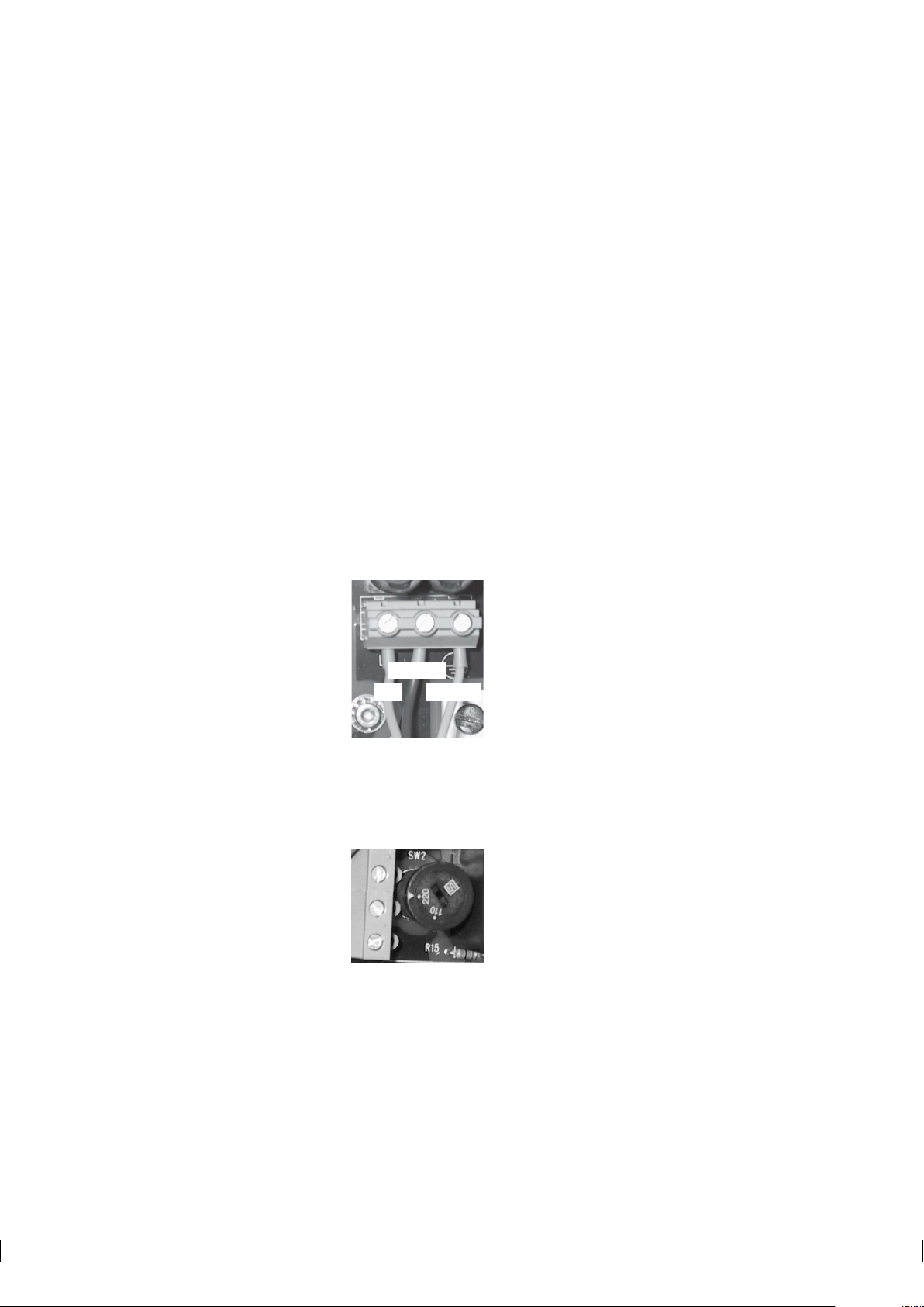
3.2.2.2 AC power connection
The primary AC power is connected to a separate terminal strip 39/40/41 marked POWER in the lower
right-hand corner of the Power supply card (Figure 3.5). The three terminals are marked 39/L, 40/N and
41/ground symbol. The connection is made by inserting each lead into the corresponding slot and tightening
the screws above the slots (Figure 3.7).
The power terminals Line and Neutral are directly connected to the transformer primary loop, and galvanically separated from the rest of the instrument. The ground terminal (41) is connected to the bottom plate of
the Indicating transmitter, to the transformer shield winding and to the outer shield of the interconnecting
cable.
Figure 3.7 Power terminals on the Power supply card
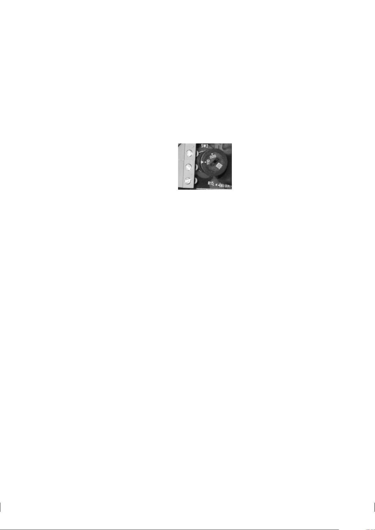
Important: Before connecting the IT-R power, check the position of the power selector switch, marked
SW2 on the Power supply card. The power selector switch has two positions: 220–240 V/50–60 Hz or
100–115 V/50–60 Hz.
Figure 3.8 Power selector switch in the 220 V position
3.2.2.3 +24 V DC power connection
The primary DC power is connected to a separate terminal strip 39/40/41 marked POWER in the lower righthand corner of the Power supply card (Figure 3.5). The terminals are marked 39/+24V, 40/0 and 41/ground
Page 19
3 Indicating transmitter (IT-R) 13
symbol. The connection is made by inserting each lead into the corresponding slot and tightening the screws
above the slots (Figure 3.7).
The ground terminal (41) is connected to the bottom plate of the Indicating transmitter, to the transformer
shield winding and to the outer shield of the interconnecting cable.
Important: The power selector switch on the Power supply card, marked SW2, must be in 110 position
(Figure 3.9) when input voltage is +24 V DC. If the switch is in the wrong position, the refractometer system
does not work.
Figure 3.9 Power selector switch in the 110 V +24 V DC position
3.2.2.4 Current output connection
The current output connection terminals are 25 and 26. The terminal 25 is plus (+) and 26 minus (-) for the
4-20 mA output signal (The detailed signal specifications are listed in Section 9.4, “IT-R Specifications”).
Recorders, controllers, indicators etc. must be connected to form a closed current loop, starting from terminal 25 passing each device, in at plus and out at minus, ending at terminal 26.
Important: Be careful not to exceed the specified load resistance, 1800 Ohm.
3.2.2.5 Serial bus connections
Terminals 8-14 on the Power supply card provide connection to K-Patents accessory units, like a Relay Unit
(see Section 4.1) and External output unit (see Section 4.2). The connection cable is of the same type as the
interconnecting cable and follows the same specifications (see Section 9.4). See Section 4.1.3, “Relay unit
mounting and connections” and Section 4.2.2, “External output unit mounting and connections” for more
information.
3.2.2.6 Input switch connections
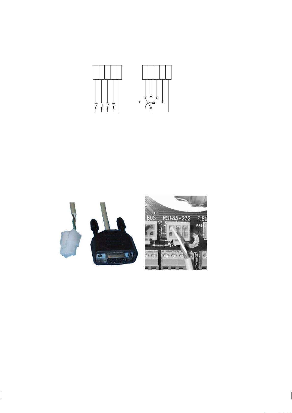
Altogether four input switches A, B, C and D can be connected: Terminals 27-A, 28-B, 29-C, 30-D, 31Common, Figure 3.10. To use a switch, you will have to connect that switch with terminal 31, which short
circuits that switch. Thus, to use switch A, connect terminal 27 with terminal 31.
The switches may be separate, or together in one rotary switch. Input switch functions are configured
through software, Section 5.6. Most commonly input switches are used for easy switching between calibration settings for different process mediums or for preventing accidental or unauthorized calibration changes.
A 5V voltage is provided over each switch. The switch terminals are all galvanically isolated from ground
and from the rest of the electronics.
Page 20
14 PR-03 instruction manual
27 28 29 30 31
SWITCHES
BCDA
27 28 29 30 31
SWITCHES
D
C
B
A
Figure 3.10 Input switch connections
3.2.3 Serial output connections: connecting a computer with the IT-R
The serial output connections on the Power supply card allow you to download information from the IT-R
with a PC computer that has a 9-pin COM port (or a USB-to-COM adapter that simulates a 9-pin COM
port).
Note: The serial output connection is for output only, i.e. it cannot be used to give commands to the IT-R.
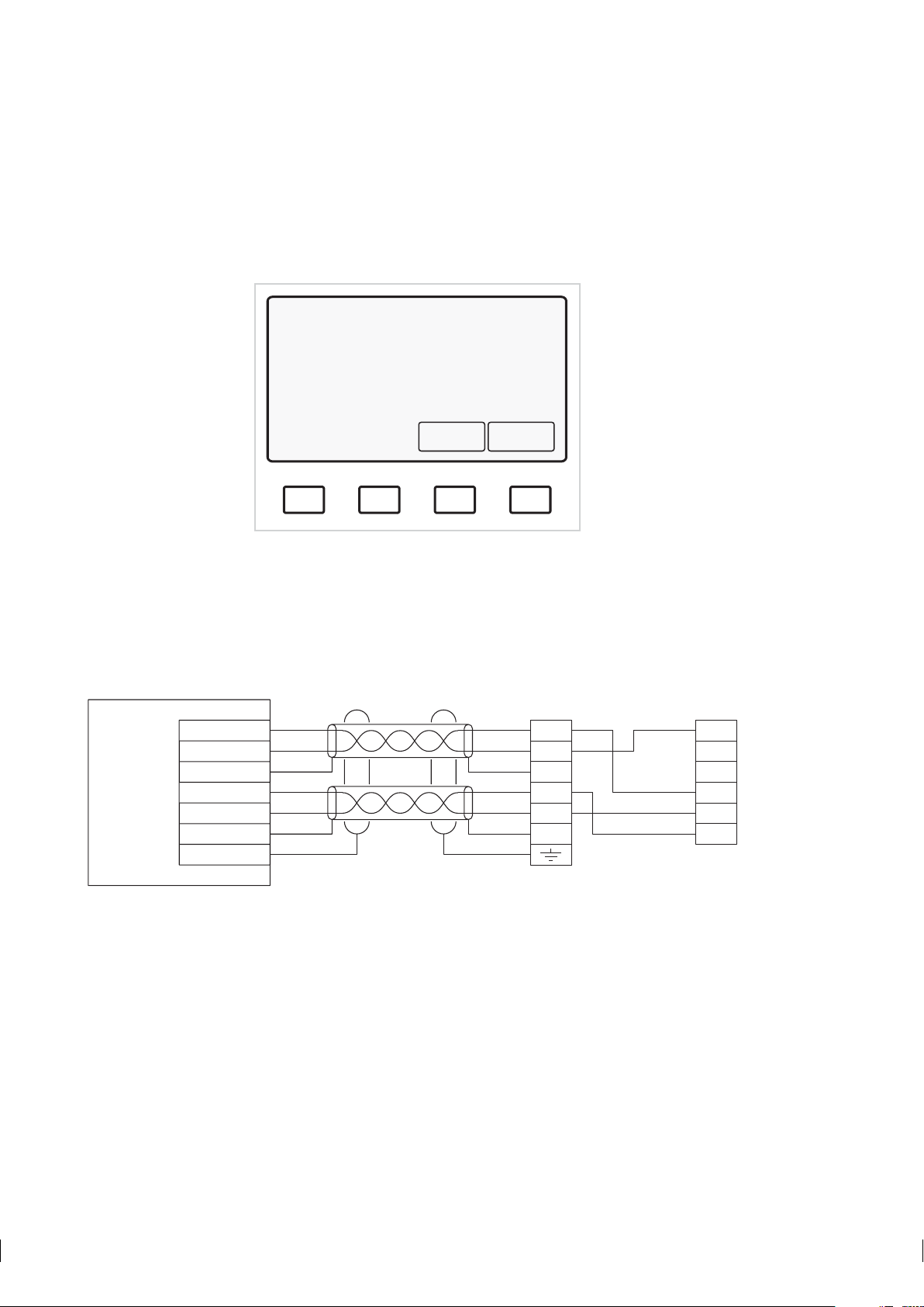
To connect your PC with an IT-R to download process data, you need to order a communications package
from K-Patents. The package contains a cable with a plug for the P3 plug connector on the Indicating
transmitter Power supply card. The other end of the cable is a 9-hole COM plug for your computer’s COM
port.
Serial connection cable plugs Cable plugged into an IT-R
Figure 3.11 Serial (PC) connection
Page 21

3 Indicating transmitter (IT-R) 15
18293104
11 27
43 47
29
45 49
15
5
12 28
44 48
30
46 50
3116
6
13 17
7
14 18
SENSOR
SERIAL BUS RS-485 SWITCHES
RLY1 RLY2
25 26
4-20mA
+-
The K-Patents communications package contains Windows software for downloading data from the IT-R.
The software has been preset so that it normally star ts directly after the installation and it has built-in
instructions. However, you can also use any standard communications software to download data. In
such case see Section 9.4.2, “Serial output specifications” for more information on the data format and
the communications settings.
3.2.4 Demo mode connection
The Indicating transmitter can be used as stand-alone for demos and to train keyboard handling. The built-in
Demo program contains a sensor simulator, so when the demo connection is on, you only need an IT-R to
show how the refractometer system works.
The Demo mode is activated by changing connections on the Power supply card:
1. Turn off the power from the IT-R. Open the enclosure cover and the front panel.
2. Disconnect the sensor cable (connections 1-7) (Section 3.2.2.1) and all connections to Serial bus (connections 8-14), i.e. all external units (see Section 4.1.3 and Section 4.2.2).
3. Connect terminal 1 to terminal 8 and terminal 2 to terminal 9, Figure 3.12
Figure 3.12 Making demo connection
4. Close the front panel and turn on the IT-R.
Page 22
16 PR-03 instruction manual
A
B
C
D
CONC
68.0%
PROCESS TEMPERATURE: 31.2 °C
STANDARD RI(25°C): 1.4194
TEST: 115.7
Normal operation
Calibrate
Display
*
11
44
22
55
33
66
RED
RED
RED
RED
BLUE
BLUE
BLUE
BLUE
SEN+
+24V
SEN-
0V
GND
GND
PGND
1
4
2
5
3
6
7
Indicating transmitter
Plug
WHITE
BLACK
BLUE
BROWN
Cable Image Digitizer
Note: When the IT-R has been turned on in demo mode, a small star appears in the top left corner of the
display. Because the external units have been disconnected, the Normal display will not have a soft key for
Prism wash. Other than that, the Indicating transmitter will behave as if it was connected to a sensor in the
process line.
Figure 3.13 IT-R display when in demo mode
Note: For more information on how to use the Indicating transmitter, see Section 5.3, “Using Indicating
transmitter”.
3.3 Cable signals between IT-R and sensor
Figure 3.14 Cable signals
Page 23
4 Accessory units 17
4 Accessor y units
4.1 Separate relay units
When necessary, a K-Patents inline refractometer system can be equipped with a separate relay unit with
either four (PR-7080) or two (-WR) relays. The separate relay units can be added to any refractometer model
when additional relays are needed.
Unlike the built-in relays, both separate relay units can be configured for preconditioning and prism wash.
That is, if a prism wash (Sanitary refractometer PR-03-A and Probe refractometer PR-03-P only) is installed
because of sticky process medium, a separate relay unit is also needed.
4.1.1 Relay unit description
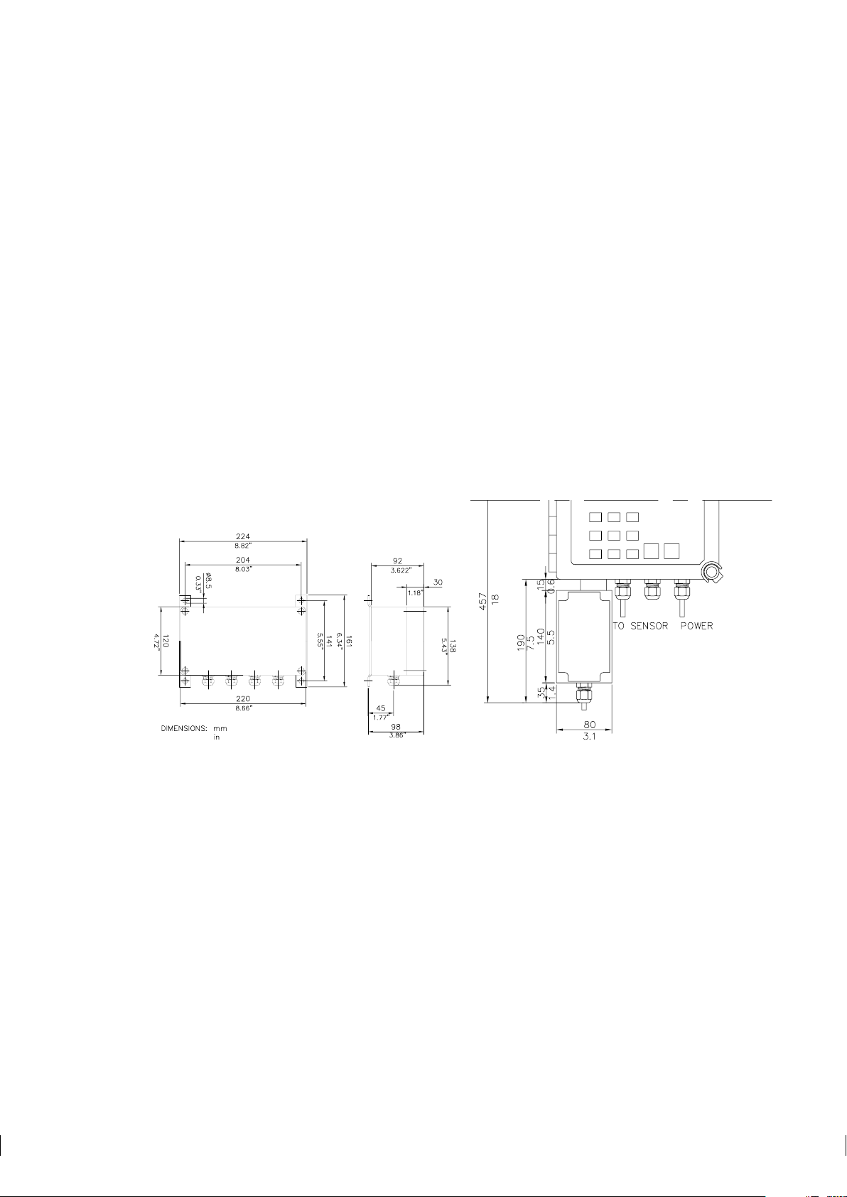
Both separate relay units are built in an enclosure with IP 65 (Nema 4X) classification. Figure 4.1 shows
the dimensions of the four-relay unit PR-7080 and the two-relay unit -WR.
PR-7080 -WR
Figure 4.1 Relay unit dimensions
To see the relays and to make all necessary connections, open the screws in the four top corners of the relay
enclosure and lift off the enclosure cover.
The cable fittings are delivered as one of the three alternatives:
US 1/2 NPT-TYPE ST-1 conduit hubs 4 pcs
European BF11/PG11 cable glands 4 pcs
M20x1.5 cable glands 4 pcs
Page 24

18 PR-03 instruction manual
4.1.1.1 Relay unit PR-7080
The Relay unit PR-7080 contains 4 relays from left to right: Relay A, relay B, relay C and relay D. There is
a yellow LED above each relay. If the LED is lighted, the corresponding relay is ON and the output contact
is closed. There is also one green and one red indicator led to inform on system status. After startup the red
led is lighted only when the relay unit has problem.
The Relay unit PR-7080 is connected with the IT-R with an interconnecting cable PR-8011 . The last three
numbers in t he cable code indicate the cable length in meters, the shortest available cable is PR-8011-001
(1 meter; 3.3 feet) and the longest possible cable is PR-8011-100 (100 meters; 330 feet).
4.1.1.2 Relay unit -WR
The Relay Unit -WR contains 2 relays from left to right: Relay A and Relay B. There is a yellow LED
above each relay. If the LED is lighted, the corresponding relay is ON and the output contact is closed.
4.1.2 Prism wash system description
Deposit build-up on the prism surface disturbs the measurement. Look out for an abnormally high concentration reading, low slope value or an upward CONC drift.
In most applications the prism will keep clean due to the self-cleaning effect. If coating occurs, check the
following:
− Sufficient flow velocity, see Section 2.2.2, “Check list for pipe mounting (PR-03-A, PR-03-D, PR-03-M)”.
− A temperature difference between process fluid and sensor probe may cause coating. This may happen
with small flows if the thermal insulation is inadequate. In some cases it helps to insulate also the clamp
connector.
In case of a coating problem, the preferred solution is to try to increase the flow velocity, e.g. by installing
a pipe portion with smaller diameter. Installing a wash nozzle can be considered, if increasing the velocity
does not provide a solution (Section 4.1.4).
Three alternative media can be used for prism wash: steam, water, high pressure water. Only external relays
(accessory units) can be configured to control the prism wash cycle, see Section 5.9 “Configuring automatic
prism wash”.
4.1.3 Relay unit mounting and connections
Note: When mounting a separate relay unit, seal all unused fittings with blind washers.
4.1.3.1 Mounting and connecting Relay unit PR-7080
The four-relay Relay unit PR-7080 is mounted on a wall or similar vertical surface using its four mounting
feet. Take the length of the interconnecting cable PR-8011 and easy access for service into account when
choosing mounting spot for the Relay unit.
Open the screws on the Relay unit and lift off cover to get access to the relay card to make the connections.
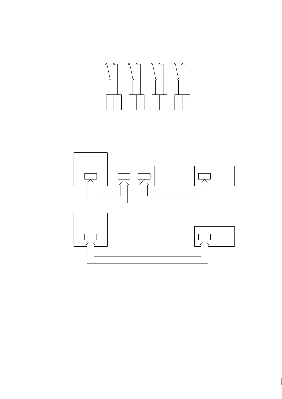
The relay contacts go to the connector strip (Figure 4.2) on the relay unit card.
Page 25
4 Accessory units 19
ABCD
44 46 48 5045 47 49 51
Indicating
transmitter
Indicating
transmitter
8-14
8-14
8-14 8-14
8-14
8-14
AB
External output unit
Relay unit
Relay unit
PR-8011
PR-8011
PR-8011
Figure 4.2 Relay unit PR-7080 connector strip
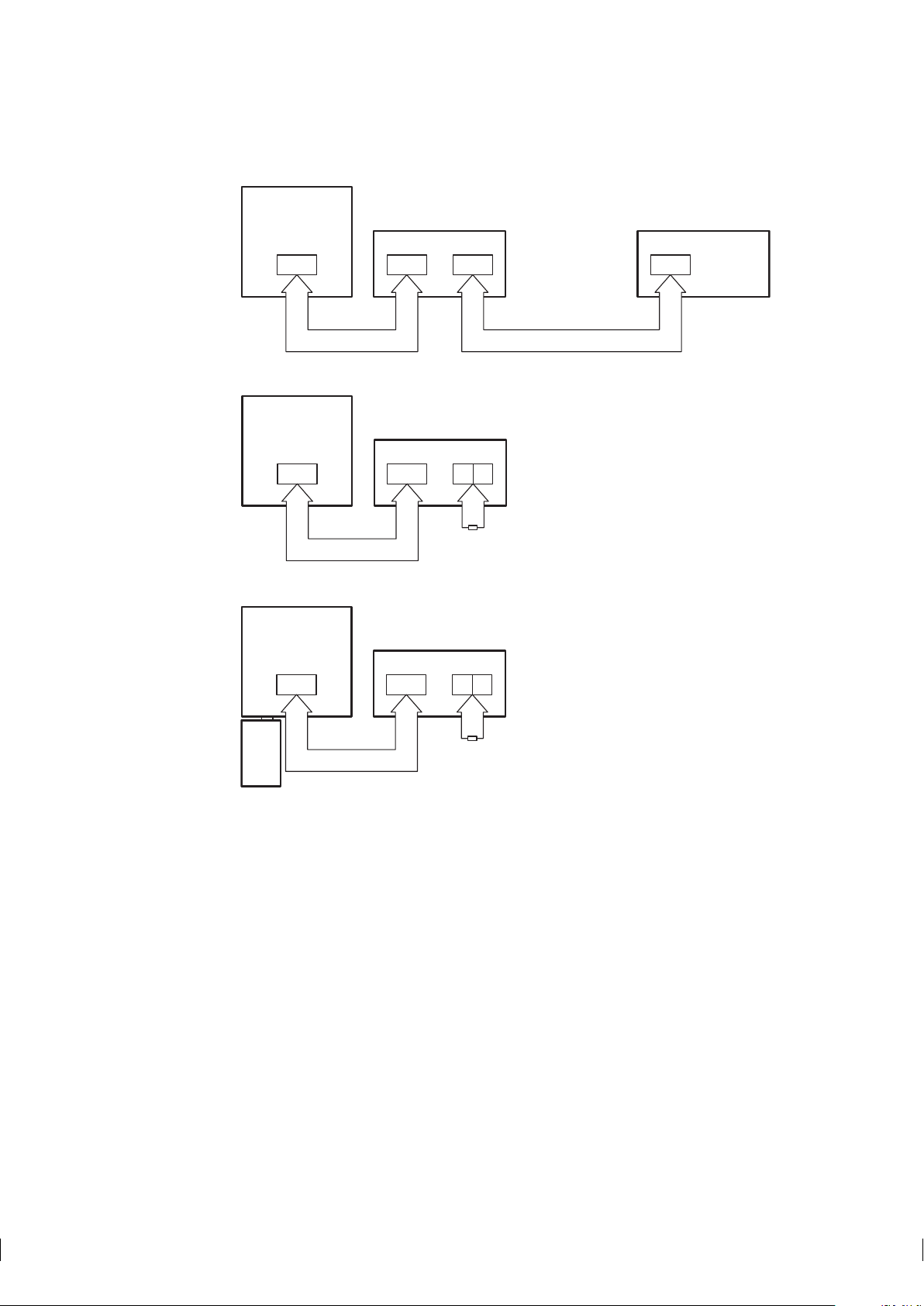
Connect the numbered leads of the interconnecting cable with the same numbers (8-14) on the serial bus.
Then proceed to connect the cable with your refractometer system. If you have an External output unit, the
Relay unit is connected to that. If no other external units are used, the Relay unit connects directly with the
IT-R (Figure 4.3).
Important: Before connecting the relay unit with your refractometer system, power off your system. If you
have an external output unit, open its cover to access the card inside for connections. If you don’t have an
external output unit, open the IT-R’s enclosure and display panel to access t he processor card.
Connect the numbered leads of the free cable end with terminals with the same numbers (8-14) on the
serial bus output (serial bus B) on the Output unit card or on the serial bus on the Indicating transmitter’s
processor card.
Figure 4.3 Connecting Relay unit PR-7080
Page 26

20 PR-03 instruction manual
4.1.3.2 Mounting and connecting Relay unit -WR
The Relay unit -WR is always mounted directly underneath the IT-R. If the IT-R and the Relay unit -WR are
delivered together, they are already fully connected. If the Relay unit is delivered separately, the connection
cable is included in the Relay unit delivery. The cable is plugged in the P2 plug on the IT-R’s processor
card (next to the sensor cable, see Figure 3.5). The relay contacts go to the connector strip.
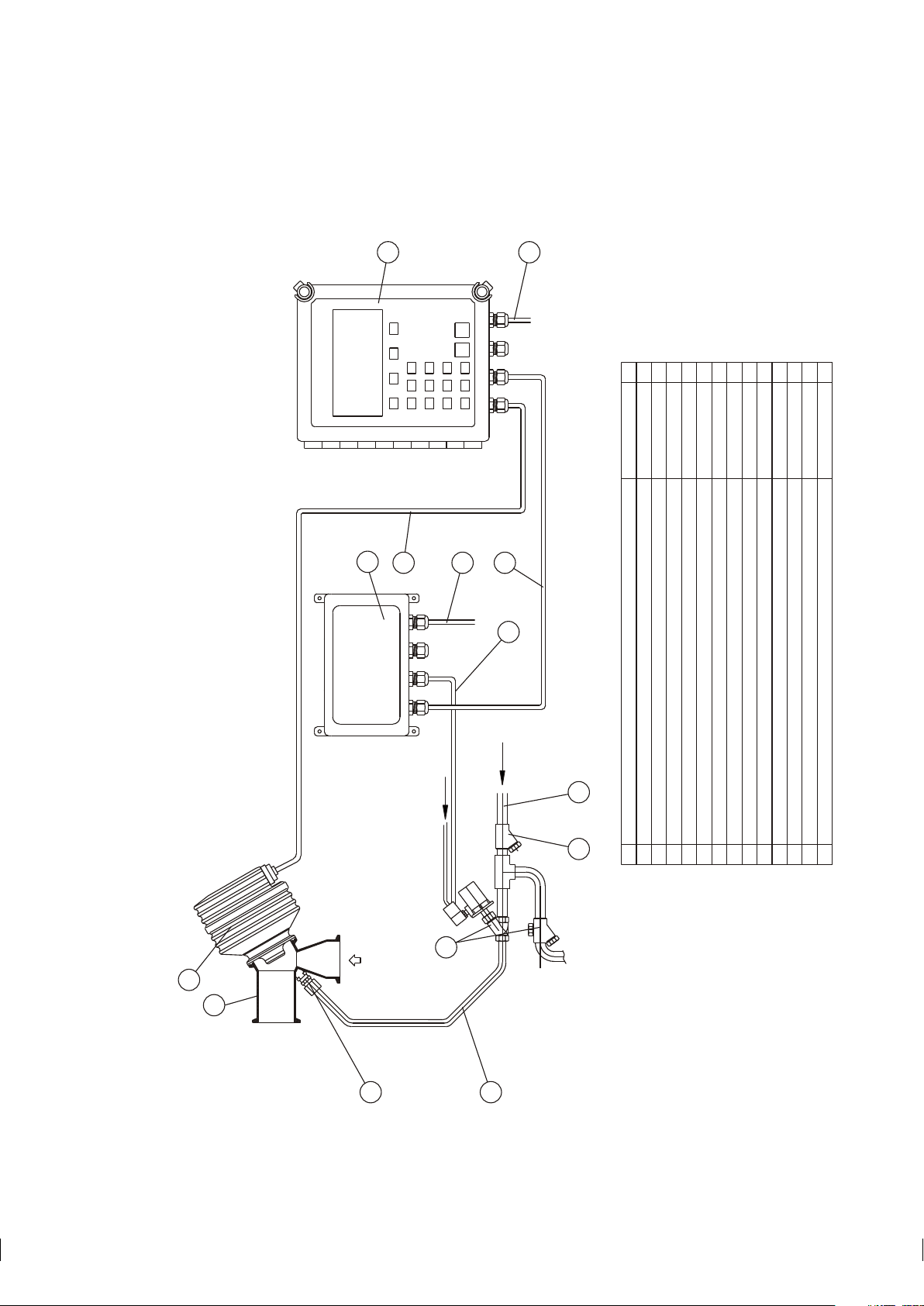
4.1.4 Mounting and connecting prism wash systems
The prism wash system for steam is described by Figures 4.7 and 4.8 and for high pressure water by Figure 4.9.
4.1.4.1 Recommended wash pressures and times
The recommended wash pressures and times are given in Table 4.1 below.
Wash medium pressure
Minimum Maximum Wash time Recovery Interval
above process allowed
pressure pressure
Steam 2 bar (30 psi) 6 bar (90 psi) 3–5 s 20–30 s 20–30 min
Water 2 bar (30 psi) 6 bar (90 psi) 10–15 s 20–30 s 10–20 min
High pressure water 40 bar (600 psi) 70 bar (1000 psi) 10–15 s 20–30 s 10–20 min
Table 4.1 Recommended prism wash parameters
Important: In steam wash, do not exceed the recommended wash times, because some process media may
burn to the prism surface if steamed for longer time. In case of coating, shorten the wash interval.
Note: In water wash, water temperature should be above the process temperature.
Note: The check valve pressure drop is 0.7 bar (10 psi).
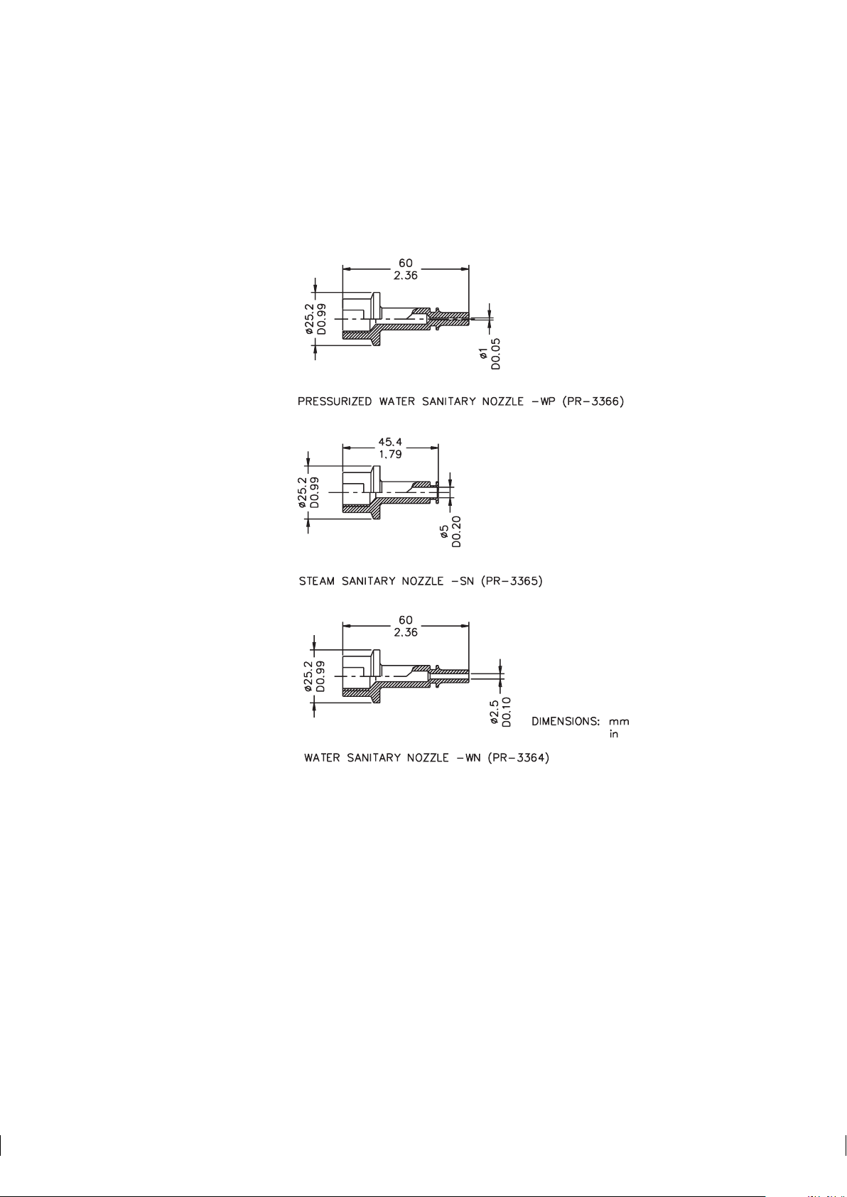
4.1.4.2 Prism wash nozzles
Select wash nozzle according to wash medium and refractometer model, Table 4.2.
PR-03-A
Pressurized water sanitary nozzle -WP PR-3366
Steam sanitary nozzle -SN PR-3365
Water nozzle -WN PR-3364
Table 4.2 Pr ism wash nozzle selection
Page 27
4 Accessory units 21
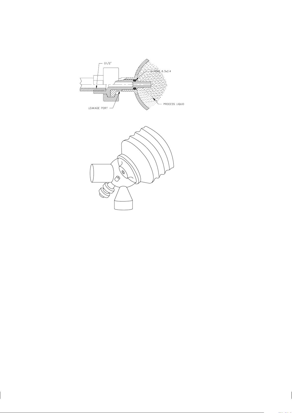
The three versions of a prism wash nozzle are shown in Figure 4.4. How they are mounted to the process is
shown in Figure 4.5, which also shows the connection of a check valve. K-Patents provides flow cells with
stud for a wash nozzle. Figure 4.6 shows an example with the correct position of the nozzle in relation to
the prism surface.
Figure 4.4 Wash nozzle selection
Page 28
22 PR-03 instruction manual
Figure 4.5 Process connection of a wash nozzle
Figure 4.6 Example of wash nozzle installed in a flow cell
Page 29
4 Accessory units 23
8
STEAM
PART SPECIFICATIONSPART SUPPLIED BY
FLOW
6
2
RELAY UNIT PR-7080
TO DRAIN
WIRING SEE WRG-314
1/2"
12
119
7
CABLE PR-8011 BETWEEN INDICATING TRANSMITTER AND RELAY UNIT
SHUT-OFF VALVE&STEAM TRAP PR-3340-230/110
CABLE PR-8300 BETWEEN INDICATING TRANSMITTER AND SENSOR
INDICATING TRANSMITTER IT-R
EFC (ELBOW FLOW CELL)
SENSOR PR-03-A62-HSS
RELAY UNIT PR-7080
7
6
5
412
3
K-PATENTS
K-PATENTS
K-PATENTS
K-PATENTS
K-PATENTS
K-PATENTS
111
111
1
5
AC POWER SUPPLY 230/110 V
SOLENOID CABLE, 3x1 (AWG 17)
STEAM PIPE 1/4"
STRAINER PR-3342
STEAM PIPE 1/2"
CHECK VALVE PR-3302
13
111012
9
8
10
4
13
3
CUSTOMER
CUSTOMER
CUSTOMER
CUSTOMER 2
111
111
13
1
K-PATENTS
K-PATENTS
K-PATENTS
AIR
4.1.4.3 Mounting of prism wash systems with steam and water
Figure 4.7 Mounting of a prism wash system with steam and Relay unit PR-7080
Page 30
24 PR-03 instruction manual
STEAM
AIR
PART SPECIFICATIONSPART
SUPPLIED BY
SWITCH
POWER
SAFETY
0
I
5
FLOW
TO DRAIN
1/2"
WIRING SEE WRG-313
10
8
6
SHUT-OFF VALVE&STEAM TRAP PR-3340-230/110
CABLE PR-8300 BETWEEN INDICATING TRANSMITTER AND SENSOR
INDICATING TRANSMITTER IT-R
EFC (ELBOW FLOW CELL)
SENSOR PR-03-A62-HSS
WASH RELAY UNIT
654
1
2
3
K-PATENTS
K-PATENTS
K-PATENTS
K-PATENTS
K-PATENTS
1
1
1
1
1
1
AC POWER SUPPLY 230/110 V
SOLENOID CABLE, 3x1 (AWG 17)
STEAM PIPE 1/4"
STRAINER PR-3342
STEAM PIPE 1/2"
CHECK VALVE PR-3302
13
12
10911
8
7
CUSTOMER
CUSTOMER
CUSTOMER
CUSTOMER
2
111
111
9
12
12
4
3
1
13
SAFETY SWITCH 1
7
2
11
K-PATENTS
K-PATENTS
K-PATENTS
CUSTOMER
14 CUSTOMERCABLE 2x1 (AWG 17) 1
14
Figure 4.8 Mounting of a prism wash system with steam and Relay unit -WR
Page 31

4 Accessory units 25
FLOW
PART SPECIFICATIONSPART SUPPLIED BY
TAP WATER, TEMP MAX 60 °C / 140 °F
SWITCH
MAIN
POWER
POWER
0
I
3/8"
POWER RELAY UNIT
PR-3603-___
12
9
1
2345687
11
CUSTOMER
AC POWER SUPPLY 230/110 V
CABLE BETWEEN INDICATING TRANSMITTER AND SENSOR PR-8300
INDICATING TRANSMITTER IT-R
EFC (ELBOW FLOW CELL)
WASH RELAY UNIT (WR)
SENSOR PR-03-A62-HSS
CHECK VALVE R 1/4" PR-3302
HIGH PRESSURE HOSE 8M
K-PATENTS
K-PATENTS
K-PATENTS
K-PATENTS
K-PATENTS
K-PATENTS
K-P / CUSTOMER
POWER SUPPLY CABLE 3 METERS FOR WATER VALVE
HIGH PRESSURE PUMP PR-3602-110/230/400/550 INCLUDING WATER VALVE
CUSTOMER
2
1
11111
1
1
1
8
1
9
7
10
8
11
12
10
POWER RELAY UNIT PR-3603-110/230/400/550 K-PATENTS 1
POWER SUPPLY CABLE 3 METERS FOR HIGH PRESSURE PUMP K-PATENTS 1
3
4
6
2
5
K-PATENTS
13
13 CABLE 2x1 (AWG 17) CUSTOMER 1
4.1.4.4 Mounting of prism wash systems with high pressure water
Warning! In high pressure wash systems, pressure increase can occur in a closed pipe section when the
!
high pressure pump is operated. K–Patents recommends to mount a pressure relief valve in the pipe section.
Relief pressure should be according to pipe pressure rating.
Figure 4.9 Mounting summary of prism wash system for high pressure water with -WR relay unit
Page 32

26 PR-03 instruction manual
4.2 External output unit PR-7090
The K-Patents inline refractometer can be provided with a separate current output unit to give e.g. a temperature mA signal.
4.2.1 Description
The External output unit PR-7090 has the same dimensions as the four-relay unit PR-7080 (Figure 4.1).
The enclosure has IP 65 (Nema 4X) classification. To open the enclosure, loosen the screws in the four top
corners of the enclosure and lift off cover. This will give access to the output unit’s circuit card.
The cable fittings are delivered as one of the three alternatives:
US 1/2 NPT-TYPE ST-1 conduit hubs 4 pcs
European BF11/PG11 cable glands 4 pcs
M20x1.5 cable glands 4 pcs
The mA output range of the Output unit is the same as the built-in mA output of the IT-R, i.e. either
4-20 mA or 0-20 mA. The output range is chosen through the IT-R’s software, see Section 5.8.
Two monitoring LEDs on the output unit’s circuit card indicate its status: Green LED L1 is lit when the
output unit is in order. Red LED L2 is lit when correct input dat a are missing. Red light means that either the
connection to the IT-R is broken (no interconnecting cable, badly plugged cable or dead cable) or that there’s
a problem on either the output unit’s circuit card or the IT-R’s processor card. Under normal operation the
green LED should be lighted and the red LED should be dark.
The External output unit is connected with the IT-R with an interconnecting cable PR-8011 . The last three
numbers in t he cable code indicate the cable length in meters, the shortest available cable is PR-8011-001
(1 meter; 3.3 feet) and the longest possible cable is PR-8011-100 (100 meters; 330 feet).
4.2.2 External output unit mounting and connections
Note: Seal all unused fittings with blind washers.
The External output unit PR-7090 is mounted on a wall or similar vertical surface using its four mounting
feet. Take the length of the interconnecting cable(s) PR-8011 and easy access for service into account when
choosing mounting spot for the External output unit.
Open the screws on the External output unit and lift off cover to get access to the circuit card to make the
connections. The output mA signal is connected to the terminals 42+ and 43-.
Connect the numbered leads of the interconnecting cable with the same numbers (8-14) on the serial bus A
on the circuit card. If you have a Relay unit PR-7080, the Relay unit’s interconnecting cable is connected to
the Serial bus B.
Important: If the refractometer system does not include a Relay unit PR-7080, close the circuit with a
120 Ohm closing resistor (Figure 4.10).
Page 33
4 Accessory units 27
Indicating
transmitter
Indicating
transmitter
8-14
8-14
8-14
8-14
8-148-14
A
A
B
B
External output unit
External output unit
Relay unit
120
Ohm
89
PR-8011
Indicating
transmitter
8-14 8-14
AB
External output unit
120
Ohm
89
-WR
PR-8011
PR-8011
PR-8011
Important: Before connecting the Output unit with your refractometer system, power off your system. Then
open the IT-R’s enclosure and display panel to access the processor card.
Connect the numbered leads of the free cable end with terminals with the same numbers (8-14) on the
serial bus on the Indicating transmitter’s processor card (if there’s an earlier Relay unit connection, move
the Relay unit’s interconnecting cable to the Output unit’s circuit card, serial bus B, and then connect the
Output unit with the IT-R).
Figure 4.10 Connecting External output unit
Page 34

28 PR-03 instruction manual
Page 35

5 Startup, configuration and calibration adjustment 29
POWER
OFF 0
ON
I
A
B
C
D
CONC
68.0%
PROCESS TEMPERATURE: 31.2 °C
STANDARD RI(25°C): 1.4194
TEST: 115.7
Normal operation
Calibrate
Display
A
B
C
D
CONC
68.0%
PROCESS TEMPERATURE: 31.2 °C
STANDARD RI(25°C): 1.4194
TEST: 115.7
Normal operation
Start
prism
wash
Calibrate
Display
5 Startup, configuration and calibration adjustment
5.1 Startup
First check that the serial number of your sensor (Figure 8.1) and your Indicating transmitter (Figure 9.1)
match. If you ordered a new sensor to go with an old IT-R, ask K-Patents to send a new label for your IT-R.
Check wiring and supply voltage, Section 3.2.2.
Open the IT-R cover and press the main power switch (Figure 5.1) underneath down to ON position to power
up your refractometer system.
Figure 5.1 The power switch
5.2 System check
After the power has been switched on, the IT-R checks the type of the sensor, which should be identified
as PR-03. The sensor code PR-03 is shown on the display for a short time. Then the Normal display
(Figure 5.2) appears. The diagnostic message should be Normal operation or, if the process pipe is
empty, Low conc/no sample. For any other message see Section 9.7.
Without wash With wash
Figure 5.2 Normal displays
The display also shows the current process temperature.
The TEST value in the display should be in the range of 8-248. The value 248 indicates a clean prism in an
empty process pipe. The value 8 means that the prism is coated and no reliable optical image is available.
As the instrument is precalibrated to your process, the concentration reading should be on scale, although it
may need some final adjustment (see Section 5.10.1). If the concentration reading is off, check your process
conditions (see Section 7, “Troubleshooting and correcting problems”).
Page 36

30 PR-03 instruction manual
A
B
C
D
CONC
36.7%
TEMPERATURE: 30.2 °C 86.4 °F
STANDARD RI(25°C): 1.3960
TEST: 133.6
Normal operation
Optical
image
System
configuration
Sensor
head
Output signal: 16.7 mA
A
B
C
D
RI(25ºC
1.4412
PR-03 version 8.5
Sensor interface version 4.0
Sensor processor version 4.0
Relay unit not connected
External output unit not connected
Output: 4..20 mA = 1.4260..1.4900 RI(25
Relay
configur-
ation
Switch
configur-
ation
Wash
times
A
B
C
D
RI(25ºC
1.4412
SENSOR HEAD
Head temperature: 20 ºC
Head humidity: 32 %
Normal operation
Press the key D (soft key Display) for additional data, e.g. output in mA. Further data is obtained in the
Information display by soft keys Optical image (Figure 5.3), System configuration and Sensor
head. Return to Normal display by pressing the RESET key as many times as necessary.
Note: Use the keyboard’s keys A, B, C, D for the soft key commands, do not touch the display screen (see
Section 5.3.1).
Information display System configuration display Sensor head display
Figure 5.3 Getting additional information
Measure the output signal. It should agree with the mA display.
If there are problems in the system check, proceed to Chapter 7, “Troubleshooting and correcting problems”.
5.2.1 Checking accessory units
All the accessory units, both relay units -WR and PR-7080 and external output unit, have two indicator
LEDs that tell about their status. Open the enclosure cover to see these LEDs. When the refractometer
system is on and the IT-R is finished with the initial check (i.e. the Normal display has appeared, see at
page 29), only the green led should be lit. If the red led stays lit, there’s problem in the accessory unit
configuration, see Section 5.7 and Section 5.8.
Note: When the refractometer system is powering up, both LEDs light up for a short time during the system
check. After a while the red led should be turned off, in a working system only the green led is lit.
5.2.2 Testing prism wash
Important: Before you test prism wash, check that there is liquid in the pipe in front of the refractometer
and that the steam washing parts are properly installed and connected.
If you are using prism wash controlled by a relay unit check the wash sequence by pressing in the Normal display soft key Start prism wash (Figure 5.2). The TEST value should clearly increase (and the
concentration reading decrease) during wash.
Note: The manual wash command cannot override External hold (see Section 5.6).
Note: The Start prism wash soft key appears in the Normal display only when a relay has been con-
figured as wash relay (Section 5.7). In demo mode it never appears, because the external units have been
disconnected.
Page 37

5 Startup, configuration and calibration adjustment 31
A
B
C
D
CONC
68.0%
PROCESS TEMPERATURE: 31.2 °C
STANDARD RI(25°C): 1.4194
TEST: 115.7
Normal operation
Calibrate
Display
A
B
C
D
CONC
68.0%
PROCESS TEMPERATURE: 31.2 °C
STANDARD RI(25°C): 1.4194
TEST: 115.7
Normal operation
Start
prism
wash
Calibrate
Display
5.3 Using Indicating transmitter
5.3.1 Keyboard functions
The keyboard has 10 number keys and four soft keys, marked with letters A-D. The meaning of a soft key
changes depending on what has been entered previously, i.e. what display is shown. The meaning of a soft
key is always displayed on the screen above the key, for example the Normal display always has soft keys
C=Calibrate and D=Display and, if the system has prism wash, also A=Start prism wash (see
Figure 5.4).
The ENTER key is used to accept entered numeral values (to "OK" them) and the RESET key is used to
cancel input and to move "backwards" in the command structure.
The commands that can be given to the Indicating transmitter have been arranged into a selection tree, i.e.
command groups and subgroups (see Figure 9.5). The "root" of the selection tree is the Normal display
(Figure 5.4), to which the IT-R always returns if it doesn’t receive any keyboard commands for a predefined
reset time (normally 60 seconds).
Figure 5.4 Normal display
Each command in the selection tree can be reached from the Normal display with its own, unique key
sequence. For example you can view the relay configuration with the sequence D (Display) - C (System
configuration) - A (Relay configuration), i.e. starting from the Normal display, press first soft
key D, t hen soft key C, then soft key A. After viewing the configuration you can go backwards to the Normal
display by pressing the Reset key three times.
Whenever New value: _ _ _ _ is displayed, new parameter values can be entered by the numerical
keys. If you accidentally enter a wrong number, you can erase it with RESET. When the number (value)
is complete, press ENTER. After this the IT-R will ask for reconfirmation with the following text: Press
ENTER to change (Otherwise press RESET). Thus, press ENTER if you want the new value
to become effective. If you want to discard the new value and return to the old value, press RESET.
Page 38

32 PR-03 instruction manual
A
B
C
D
CONC
36.7%
TEMPERATURE: 30.2 °C 86.4 °F
STANDARD RI(25°C): 1.3960
TEST: 133.6
Normal operation
Optical
image
System
configuration
Sensor
head
Output signal: 16.7 mA
Example: You need to change the bias (see Section 5.10.2) to be 25.456 (as in the example in
Section 5.10.2). Starting from the Normal display (Section 5.3), you have to perform following
steps:
1. Give the right command sequence to get to the value to be changed, in this case
Calibrate/Parameters/CONC (R.I.)/Parameters/Bias
(key sequence C-B-A-A-1).
2. Type the new value.
3. When the new value is finished, press ENTER.
4. Accept (=reconfirm) the new value by pressing ENTER again. The new value now appears on
the screen as the current value.
5. Finally, withdraw from the current display by pressing the RESET key as many times as necessary (five times to get to the Normal display from the Bias setting).
5.4 Soft key Display: Getting information on the process
and the settings
Pressing the soft key Display (key D) in the Normal display brings up the Information display , Figure 5.5 below. Through the Information display you can get information about the process, the process
parameters and other settings that have been entered to the Indicating transmitter. This branch of the selection tree (Figure 9.5) is safe, because it doesn’t allow you to make changes to the settings, it will only
display the existing information.
As you can see in Figure 5.5, the Information display contains additional data compared to the Normal
display:
− The process temperature in both◦C and◦F
− The standard RI (25◦C). This shows the Refractive Index of liquid applied to the prism, referenced to
25◦C
− output current in mA
Figure 5.5 The Information display
Page 39

5 Startup, configuration and calibration adjustment 33
A
B
C
D
Slope
TEST: 248.0
30.2 ºC
Endp: 11
L): 30.5
R(: 5.3
HT: 20 ºC
HH: 4 %
SCALED
OPTICAL
IMAGE
Low concentration / No sample
A
B
C
D
Slope
TEST: 133.6
30.2 ºC
Endp: 11
L): 16.5
R(: 30.3
HT: 20 ºC
HH: 4 %
SCALED
OPTICAL
IMAGE
Normal operation
5.4.1 Viewing the Optical image
You can view the Optical image (Figure 5.6) by pressing the soft key Optical image (key A) in the
Information display. The light area (high pulses) is to the left, the dark area (low pulses) is to the right,
compare to Figure 2.2. The vertical scale is 0–100% of highest pulse amplitude, the horizontal scale
expresses the numbers of the photocells 0–1024.
Figures 5.6 below show some typical optical images appearing at startup.
Empty pipe Normal conditions
Figure 5.6 Typical optical images
Press the RESET key to return to the Information display from the Optical image display.
5.4.2 Viewing System configuration
You can view the System configuration, i.e. information about your refractometer system settings, by pressing the soft key C (= System configuration) in the Information display. The System configuration
display contains:
− Main program and sensor processor and sensor interface processor versions
− Connection and processor versions of accessory units
− Current output scale: E.g. 4–20 mA = 40.0–60.0 CONC%
− Three soft keys:
− Relay configuration (key A); for details see Section 5.7, “Configuring relays”.
− Switch configuration (key B); for details see Section 5.6, “Configuring input switches”.
− Wash times (key C); for details see Section 5.9, “Configuring automatic prism wash”.
Press the RESET key to return to the Information display from the System configuration display.
5.4.3 Checking conditions inside sensor head
By pressing the soft key D (= Sensor head) in the Information display you will find out what the
conditions are inside the sensor head:
− Head temperature
− Head humidity
This is very useful information when suspecting a problem in the sensor head, for details see Section 7.2.2.
Page 40

34 PR-03 instruction manual
A
B
C
D
RAW
SENSOR
DATA
RMN: 2
RMX: 216
LED: 96
Scans: 2
A/D: 314
Sts: 00h
HT: 143
HH: 10
Scaled
image
Normal operation
5.5 Soft key Calibrate: Viewing and changing system settings
5.5.1 Viewing Optical image and raw data
It is possible to view all raw data from the sensor including the optical image followed by the Scaled
Image, Slope and Image Diagnostics displays (see the selection tree, figure 9.5). Starting from the Normal
display, select Calibrate/Optical image to get the complete optical image. The display (Figure 5.7)
contains now all raw data from the Sensor including the signals from each photo cell, i.e. the raw video
signal. This differs from the Optical image, Figure 5.6, selected through the Display key.
Figure 5.7 Complete optical image with raw data
For information on the diagnostic messages shown on this screen, see Section 9.7.
5.5.2 Raw data explanations
RMN, RMX Minimum and maximum of the raw video signal. This signal is calculated on the Processor
card from the video signal. The scale is 0-255, corresponding to full scale on display. The
light intensity is controlled to keep RMX in the range 170-190.
LED The LED exposure control signal on a light intensity scale 1-255. The flashing red light of
the LED can be seen directly. If the operation is correct, the displayed LED value should be
above 20 and below 200.
Scans Number of optical images during one calculation cycle, typically 1 or 2. The scan pulses
(with 5 V amplitude) can be measured at TP 3
A/D This refers to the temperature measurement
Sts Sensor status bits determined by the type of Image Detector card: "04h" indicates a Process
refractometer PR-03. One bit added, "05h", indicates DETECTOR TIMEOUT.
Page 41

5 Startup, configuration and calibration adjustment 35
A
B
C
D
SCALED
OPTICAL
IMAGE
TEST: 115.9
51.2 °C
Endp: 21
L): 9.8
R): 25.9
HT: 20 °C
HH: 3%
Slope
Normal operation
HT Sensor head temperature sensor reading. This value is used in calculating the actual Sensor
head internal temperature.
HH Sensor head humidity sensor reading. The actual relative humidity inside the sensor is cal-
culated from HH and HT.
5.5.3 Viewing Scaled image
In t he scaled image (Figure 5.8) the optical image has been modified mathematically to make a clearer
curve.
Figure 5.8 Scaled image display
The Scaled image display provides following information:
TEST: The calculated TEST value, i.e. the number of photocells on the lisght side of the optical image
(to the left fo the vertical line). Range 8–248. Indicated by a dotted vertical line.
(T) Indicates the process temperature.
Endp: The vertical intensity value of the rightmost point in % of span.
L): A measure of the left side curvature of the optical image.
R(: A measure of the right side curvature of the optical image.
A zero curvature indicates a straight line. Both curvature values are defined as positive for an
image as Figure 5.5.3.
HT: Sensor head internal temperature in◦C.
HH: Sensor head internal relative humidity in %RH.
5.5.4 Viewing slope
The Slope display (Figure 5.9) shows the slope curve of the optical image. Slope is a measure of the
sharpness of the optical image.
The SLOPE curve should have a sharp dip at the TEST value. The following additional values are given:
Page 42

36 PR-03 instruction manual
A
B
C
D
Diagnostics
SLOPE
TEST: 115.7
31.2 °C
Max: 208
Slope: 2.7
Endp: 21
L): 10.1
R(: 25.8
Normal operation
Figure 5.9 Slope display
Max: The filtered value of the maximum light intensity RMX of the raw data (Figure 5.7).
Slope: The absolute value of the slope curve dip at TEST. The value of Slope must be above 1 to be
acceptable.
5.5.5 Viewing Image diagnostics
The Image diagnostics display lists the critical values for TEST acceptance:
Max intensity OK (above 100)? Yes/No
Endpoint below 75 %? Yes/No
Image below corner? Yes/No
Slope OK (above 1)? Yes/No
Left curve OK (above 1)? Yes/No
Right curve OK (above 1)? Yes/No
For measurement with a normal sample, all answers should be Yes. A message Dip in image may
appear if the optical image is irregular.
5.6 Configuring input switches
To reach the input switch configuration settings from the Normal Display, use the command sequence
Calibrate/Parameters/Switch inputs.
The microprocessor accepts four switch inputs: A, B, C and D (for connections see 3.10). The function of
each switch can be individually defined from one of the following five alternatives:
0 Not defined (factory setting).
1 Scale select Select parameters for alternative process mediums. There are all to-
gether four alternative mediums selectable by closure of the corresponding switch. If no selection switch is closed, the normal medium
is selected. Maximum number of mediums is five (Normal, A, B, C,
Page 43

5 Startup, configuration and calibration adjustment 37
A
B
C
D
RI(25ºC
1.4412
SWITCH INPUT A (Not defined)
0 Not defined
1 Scale select
2 Ext hold & wash start
3 External wash stop
4 Calibration seal
Switch
B
Switch
C
Switch
D
Figure 5.10 Switch input display for input A
D).
Note: The range will not change.
Example: medium 1 = 20 - 40 % Sugar, medium 2 = 20 - 40 % Salt.
2 Ext hold & wash start Remote wash start for Relay unit wash function and external Hold.
This switch function is useful for an intermittent process: the prism
is washed when the process stops and again when it starts, between
the two washes the output signal is on Hold.
Only Sanitary refractometer PR-03-A, Probe refractometer PR-03-P
and Process refractometer PR-03-D.
3 External wash stop Only Sanitary refractometer PR-03-A, Probe refractometer PR-03-P
and Process refractometer PR-03-D.
4 Calibration seal An input switch can be configured for calibration seal. Activating and
connecting the input switch for calibration seal will prevent calibration through software.
5.7 Configuring relays
You can check the existing relay configuration and functions with the Indicating transmitter. Press the
key sequence Display/System configuration/Relay configuration to display the current
relay settings.
The default setting for built-in signal relay 1 is No malfunction and for signal relay 2 Internal
humidity above 50 %. A closed contact on the Relay 1 indicates that the instrument works properly.
It is recommended to use this relay for alarm purpose in a control system.
In relay units, Relay B is configured for wash by default.
You can reprogram the relay functions any time through the IT-R’s calibration menu by performing t he
following steps:
Page 44

38 PR-03 instruction manual
1. Press Calibrate/Parameters/Relays.
2. For built-in relays select either soft key A, Relay1, or soft key B, Relay2.
For a relay unit select key 3, Relay unit and then select the relay to be programmed (in -WR relays
A and B, in PR-7080 relays A, B, C, D).
3. Select the relay function
0 Not defined
1 Processor OK The relay is ON if the processor is running
2 Normal operation The relay is ON if the diagnostic message is
Normal operation.
3 No malfunction The relay is ON if the diagnostic message is
Normal operation or Low conc/no sample.
4 Low limit Low alarm relay, relay is ON if value below limit.
First choose an alarm source from the following list:
− CONC %
− Standard RI (25◦C)
− TEMP◦C
− TEMP◦F
− TEST
− Sensor temperature
− Sensor humidity
Then enter a alarm limit. The default value of the limit is zero.
5 High limit High alarm relay, relay is ON if value above limit.
First choose an alarm source from the following list:
− CONC %
− Standard RI (25◦C)
− TEMP◦C
− TEMP◦F
− TEST
− Sensor temperature
− Sensor humidity
Then enter a alarm limit. The default value of the limit is zero.
6 Preconditioning A preconditioning relay. Relay unit only.
7 Wash A wash relay. Relay unit only.
8 In divert control Not used with PR-03.
Important: An alarm relay configuration always requires the following information: high or low limit,
alarm source and alarm limit. The configuration is not complete until all the information is entered to
the IT-R.
Note: If needed, you can adjust alarm delay by pressing the key 4, Alarm delay in the Relays display
(Calibrate / Parameters / Relays). The same delay applis to all relays and is used to prevent
oversensitive alarms. The source value has to be out of limits during the whole delay time, given in seconds,
to activate the relay. The default value for the alarm delay is ten seconds.
Page 45

5 Startup, configuration and calibration adjustment 39
A
B
C
D
RI(25ºC
1.4412
EXTERNAL OUTPUT UNIT (Not connected)
1 Zero (0.0000)
2 Span (0.0000)
3 Hold function (Active)
4 Range (4..20 mA)
5 Source (Not defined)
5.8 Configuring external output unit
To program the External output unit from the keyboard of the Indicating transmitter, start with the sequence
Calibrate / Parameters / Output signals / External output to get the External
output unit display (Figure 5.11).
1 Zero Measurement value corresponding to 4 mA or 0 mA (depending on your cho-
2 Span Measurement value span corresponding to mA output span
3 Hold function Select either 0 Inactive or 1 Active
4 Range Select either 0 4..20 mA or 1 0..20 mA
5 Source Select from
Example: For source◦C, zero = 20, span = 80, the output signal 4 - 20 mA corresponds to 20-100◦C.
5.9 Configuring automatic prism wash
The relay units -WR and PR-7080 can be configured to control prism wash. Automatic prism wash can be
initiated with regular intervals (Section 5.9.1) or based on cer tain measurement values (Section 5.9.2). It
is also possible to configure these automatic wash functions so that they are not used when the process is
stopped or the pipe is empty (Section 5.9.3 and Section 5.9.4).
Figure 5.11 External output unit display
sen range)
0 Not defined
1 RI (25◦C)
2 Standard RI (25◦C)
3 Temp◦C
4 Temp◦F
5 TEST
6 Sensor temperature
7 Sensor humidity
Page 46

40 PR-03 instruction manual
WASH
RECOVERY
INTERVAL
PRECOND.
5.9.1 Timed wash
When an external relay unit is used as a wash timer, the time settings are entered after the sequence Calibrate / Parameters / Prism wash:
− Preconditioning time s (0)
− Wash time, s (3)
− Recovery time, s (30)
− Wash interval, min (20)
The default values for timed wash are given in parenthesis. The output signal is locked during wash and
recovery time.
Figure 5.12 Prism wash sequence
Note: The wash interval timer starts a wash at a preset interval after last wash, independently of how the
last wash was initiated. If the wash interval is set to zero, the timer will not initiate a wash.
Wash type Time Pressure Recovery Interval
Steam wash 3-5 sec. 5-6bar (73-87 psi) 20-30 s 20-30 min
High pressure water wash 10-15 sec. 20-30 bar (290-435 psi) 20-30 s 10-20 min
Table 5.1 Recommended prism wash times for the PR-03 sensors
Important: In steam wash, do not exceed the recommended wash times, because some process media may
burn to the prism surface if steamed for longer time. In case of coating, shorten the wash interval.
5.9.2 Smart wash
Sometimes it is necessary to modify the standard wash routine to fit the application better. The Smart wash
feature allows you define better when wash is needed and when it should not be implemented.
The Smart wash starts the wash when the prism shows signs of being coated. An early indicator of beginning
coating is that the Slope decreases. Slope is a measure of the sharpness of the optical image (Section 5.5.4).
The Smart wash settings are made at Calibrate / Parameters / Prism Wash / Smart
wash:
Slope limit A wash is initiated when the Slope value goes below this limit. The Slope limit has to
be set based on observations of slope values both at clean prism and at slight coating.
When the slope limit is set to zero, this Smart wash function is inactive.
Page 47

5 Startup, configuration and calibration adjustment 41
Minimum time This parameter sets a limit to how often the Smart wash is allowed to start a wash, its
range is 0–1440 min.
When this parameter is zero, the Smart wash function is inactive.
Maximum test This parameter should normally be set to zero. Then it will not influence the Smart
wash function. It may be used for fine-tuning: The Smart wash will initiate wash only
if the Test value is below Maximum test.
5.9.3 Preventing automatic wash
Note: The preconditioning and wash relays are not activated by automatic wash start under Low conc /
no sample as this indicates a clean prism in an empty process line, i.e. there is no need for washing the
prism.
Wash can be prevented when the process temperature is below a limit. The Wash stop function is used to
prevent steam wash when the process pipe is empty or when the process is stopped. To activate the wash
stop use the command sequence Calibrate / Parameters / Prism wash / Wash stop /
Activate and set the temperature limit. The default value for wash stop is inactive. When
the wash is not accepted the diagnostics message is Wash stop/temp. limit, see Section 9.7.
Wash can also be prevented by an external contact closure, telling e.g. that the process pump has stopped.
See Section 5.6.
5.9.4 Prism wash check
The prism wash check is used for making sure that the wash really has an effect on the prism, i.e. that the
wash works correctly. A prism wash is accepted if one of the two conditions are satisfied:
1. TEST exceeds "TEST limit", i.e. the TEST value reaches the set limit during wash cycle
2. TEST increases more than "TEST difference", i.e. the TEST value increases during wash reaching the value of normal TEST plus the given TEST difference.
The default values of "TEST limit" and "TEST difference" are zero, which makes the Wash check inactive.
If one of the conditions are set to zero, the other condition is valid alone.
Example: A typical case is "TEST limit" = 230, "TEST difference" = 0. The wash is accepted, if the
Test value exceeds 230 during wash, and the Test difference condition is invalid.
Page 48

42 PR-03 instruction manual
WASH
STOP ?
EXTERNAL
HOLD ?
Start
prism
wash
REMOTE WASH
SWITCH
NO
YES
YES
NO
Automatic Wash start
1. Wash interval timer
2. Smart Wash
YES
NO
WASH
RECOVERY
WASH
CHECK
OK?
RETRY
WASH ?
NO
YES
“Prism wash
failure“
Reset “Prism
wash failure“
Manual
Figure 5.13 Wash decision logics
Page 49

5 Startup, configuration and calibration adjustment 43
If the wash is not accepted, the diagnostic message will be Prism wash failure (see Section 9.7
for more information). This message is reset from the keyboard "Reset" or by a successful wash. A Wash
retries parameter defines how many times wash is tried. The prism wash retries parameter is set with
Calibrate / Parameters / Prism wash / Wash check / Wash retries, the default
value (number of retries) is zero.
5.10 Adjusting concentration calibration
A K-Patents inline refractometer system is always delivered precalibrated according to the information given
by the user. The refractometer does not need any mechanical adjustments, all adjustments or changes of
range are made by keyboard entry only (Sections 5.10.2 and 5.10.3). The final calibration to obtain full
accuracy is made by collecting data from the actual process and sending that data to K-Patents or local
K-Patents representative for calculations and new calibration parameters (Section 5.10.6).
5.10.1 Checking current calibration
Wait until normal process conditions occur. The instrument is precalibrated at delivery, so a correct output
should be obtained automatically. If output is badly off-scale, check your process conditions.
If the diagnostic message is Normal operation but the concentration reading is not what could be
expected based on laboratory determinations, the deviation can be corrected with a calibration constant
bias, see Section 5.10.2 below.
If the concentration reading is correct, but not the output mA, see Section 5.10.3 below for adjusting the
concentration reading.
The temperature by the refractometer sensor may not be exactly the same as the temperature given by a
separate process temperature sensor. Normally, a constant slight deviation in the temperature by the sensor
is not critical. However, it is possible to calibrate the sensor to give the exact process temperature, see
Section 5.10.4, “Temperature calibration”.
The damping of the concentration measurement may be increased if necessary e.g. to get a smoother
recorder track, see Section 5.10.5.
5.10.2 Concentration calibration from keyboard
The concentration display should be in agreement with laboratory determinations. If t he diagnostic message
is Normal operation, deviations can be corrected from keyboard by adding a calibration constant
bias value . A change of the calibration constant bias influences t he Conc% reading the same amount.
Key in Calibrate/Parameters/CONC (R.I.)/Parameters/Bias to read and change the Bias.
Example: If the CONC% display is 26% and the laboratory determination is LAB% = 28%, then a
value Bias = 23.456 should be changed to Bias + LAB% - CONC% = 25.456.
Note: The CONC% reading is restricted to positive values even if the mathematical calculation gives a
negative value. For a negative CONC% the display shows "0.0". For BIAS adjustment it is useful to know
the real CONC% value. For this reason the calculated negative CONC% reading is shown in the Calibrate
branch of the Selection tree, Figure 9.5.
Page 50

44 PR-03 instruction manual
Warning! Never try to change bias in a day-to-day manner, or week-to-week. Frequent bias changes will
!
increase the measurement variation, not decrease it.
Amplification adjustment: The size of CONC% changes is directly proportional to the calibration constant
Gain. The point, where TEST = 128, is not influenced by Gain. From two measurement points the new
Gain can be estimated by the formula
New Gain = Old Gain * (LAB%1 - LAB%2) / (CONC%1 - CONC%2).
After the change of the Gain, the Bias has to be determined by a new sample.
The constants Square and Cube are linearity corrections that can be provided by K-Patents, see Section 5.10.6.
5.10.3 Output current range selection
It is possible to change t he concentration range of the output current even after the instrument is installed
and operating. The change is made through the display
Calibrate/Parameters/Output signals/Current output.
Example: To change 4–20 mA = 15–25 CONC% to 4–20 mA = 10–30 CONC%, key in the sequence
Calibrate / Parameters / Output signals / Current output
and then enter Zero = 10 and Span = 20.
5.10.4 Temperature calibration
Normally the process liquid temperature is considerably higher than the ambient. Then the heat loss through
the refractometer sensor may cause the temperature display to be somewhat lower than the process temperature. This will not impair the measurement, and the difference can be ignored.
If, however, the temperature has to show an absolutely correct value, then a bias in◦C can be added to the
temperature reading by giving the following key sequence
Calibrate/Parameters/Temperature/Temp bias and entering the bias in degrees centigrade.
Note: A change of Temperature bias will cause a small change in the concentration output, due to the
temperature compensation. If necessary, this change can be compensated with a Bias change (see Section 5.10.2).
5.10.5 Adjusting damping time
The damping time is the time it takes for the concentration measurement to reach half of its final value at
a step change of the concentration. For example, if concentration changes from 50 % to 60 % and damping
time is 10s, it takes 10 seconds for the IT-R to show concentration 55 %. Figure 5.14 below shows how the
damping time affects the measurement curve.
The damping time is set in seconds with the key sequence
Calibrate/Parameters/Conc (R.I.)/Damping time. A damping time of 5–15 seconds
seems to work best in most cases, the factory setting is 5 sec.
Warning! Avoid overdamping, the signal should not be made insensitive.
!
Page 51

5 Startup, configuration and calibration adjustment 45
35
40
45
50
55
60
0 10 20 30 40 50 60 70 80 90 100 110 120 130 140 150
Time [s]
CONC%
Undamped
5 s 10 s
30 s
Figure 5.14 Effect of damping time on measurement
5.10.6 Field calibration
The most accurate calibration is made under normal process conditions using your standard laborator y
determinations of sample concentration. K-Patents provides a field calibration service that optimizes the
calibration constants based on the data supplied.
You should systematically record calibrating data on the Calibration data report (page 109, also available
at www.kpatents.com and by email at info@kpatents.com). When you have completed the Calibration data
report, you have to fax it to either K-Patents headquarters or your local K-Patents representative. A computer
analysis of the data will be made at K-Patents and optimal calibration data will be sent to you to be entered
in the IT-R.
For a complete report you need 10–15 valid data points (see below). A data point is of use for calibration
only when the diagnostic message is Normal operation. If prism wash is employed, do not take
samples during the wash. A data point is useful even if the concentration value is outside the range of the
output current. Each data point consists of:
LAB% Sample concentration determined by the user.
From IT-R display: (see Section 5.3)
CONC% Measurement in concentration units
TEST Number of photocells on the light side of the optical image (= primary measurement)
TEMP Process temperature measurement in centigrades
Accurate calibration is only achieved if the sample is taken correctly and the data points are recorded
carefully and only when the message is Normal operation. Pay special attention to following details:
− The sampling valve and the refractometer should be installed close to each other in the process.
− Warning! Wear protective clothing appropriate to your process when operating the sampling
!
valve and handling t he sample.
− Run the sample before starting to collect data points to avoid sampling old process liquid that
has remained in the sampling valve.
− Read the values CONC%, TEST and TEMP in the IT-R’s display at exactly the same time with
sampling.
− Use a tight container for the sample to avoid evaporation.
Page 52

46 PR-03 instruction manual
5.10.7 Bench calibration
The calibration of your refractometer system can be checked offline using Standard RI liquids. These are
available at K-Patents with part number PR-2003. The complete set of 10 bottles covers the RI range 1.310-
1.540.
Standard RI liquids are also available directly from: Cargille Laboratories, 55 Commerce Road, Cedar
Grove, New Jersey 07009, USA. WWW: http://www.cargille.com/, e-mail: cargillelabs@aol.com, phone:
973-239-6633, fax: 973-239-6096.
The bench calibration should be done at room temperature, but the temperature does not have to be exactly
25◦C as the displayed value is temperature compensated. If the sensor is hot, let it cool down to ambient
temperature.
Use a sample holder, Figure 5.15 and "strip" the sensor, i.e. use PR-03-M sensor without the flow cell and
PR-03-W sensor without the valve body. Sample holders are available at K-Patents with part number PR1010 for Sanitary refractometer PR-03-A, PR-1012 for Probe refractometer PR-03-P and Compact process
refractometer PR-03-D.
Figure 5.15 Sample holder PR-1010
Use the same three R.I. liquids t hat were used for the Delivery Data Sheet of this sensor. See Appendices B,
“Information about Delivery data sheet (DDS)”, and D, “Instrument verification ISO 9000”, for more
information.
Just a few drops of sample are enough for reliable measurement. However, the sample must be covered to
prevent outside light to reach the prism. Sample leakage from holder may give measurement error. Always
use repeated measurements for each sample. Note: Clean the prism and the sample holder well with alcohol
between the different R.I. samples.
Important: Dispose of used RI liquids. Never put liquids back into the bottle after use!
Important: Offline calibration using process liquid very seldom gives reliable results, problems are caused
by
− low flow which makes sample to form an unrepresentative film on the prism
− sample evaporation at high temperature or undissolved solids at low temperature giving devia-
tions from laboratory determinations
− an ageing sample which is not representative
− outside light reaching the prism
Thus calibration using the process liquid should always be made inline, see Section 5.10.6, “Field calibration”.
Page 53

6 Regular maintenance 47
6 Regular maintenance
The need for regular maintenance is minimal, due to the construction with no moving parts, no trimpots and
with a solid-state light source. The following rules apply:
• Keep the sensor head and the Indicating transmitter clean and dry.
• Check that the ambient temperature is not above +45◦C (113◦F). The sensor head should not be too hot
to keep a hand on.
• If your refractometer has prism wash, check that it works (in Normal display, press the soft key A,
Prism wash).
6.1 Checking the sensor moisture
The PR-03 sensor has an internal moisture detector. The moisture reading can be checked on the Indicating
transmitter display (Display / Sensor Head). Check the moisture reading once in a quarter.
An increasing signal indicates either condensate forming in the sensor head (if the process temperature is
below ambient) or prism leakage. If the moisture reading exceeds 30 %, replace the dryer (see below). If
the reading exceeds 50 %, check the prism seals.
The dryer (desiccant) is a plastic package inside the sensor head cover. When the dryer is effective, it is
yellow. When it turns green, it needs to be replaced. The dryer cannot be reactivated by any means, it
must be replaced. You can order new dryer packages (drying agents/desiccants), spare part number PR-
9107, from K-Patents or your local distributor.
For instructions on how to open the sensor head to replace the dryer, see Section 6.3 for the standard length
sensors (Sanitary refractometer PR-03-A, Compact process refractometer PR-03-D, Process refractometer
PR-03-M and Valve body refractometer PR-03-W) and Section 6.4 for the Probe sensor PR-03-P.
6.2 Checking and replacing prism or prism gaskets
Once a year check t hat the prism surface is smooth and clean. If the prism is scratched or the gaskets seem
to leak, order spare parts from K-Patents or your local distributor and follow the procedure described below
to replace them.
Page 54

48 PR-03 instruction manual
6.3 Disassembling and assembling a standard length sensor
Warning! Always check that the pipeline is empty before removing a sensor from the process line. Never
!
remove the sensor if there is process liquid in the pipe.
6.3.1 Disassembling the sensor
1. Disconnect the cable. Apply the two connector protection caps. Remove the sensor from the process
and rinse it well.
Warning! Wear appropriate protective clothing and be very careful when removing the sensor from the
!
process line!
2. Fix the sensor by the sensor head (T) in a vertical position, sensor label upwards, Figure 6.1. K-Patents
Service stand PR-1002 can be used.
Figure 6.1 Sensor in disassembly position
3. Remove the nut of the Vee-clamp. Move the Vee-clamp one step downwards.
4. Lift the sensor cover and disconnect the cable (A) from the image digitizer card.
Page 55

6 Regular maintenance 49
5. Disconnect the ribbon cable (B), the LED lead (C), and t he temperature element lead (D).
6. Remove the Image digitizer card kept by four M4 screws (E).
7. Remove the Image detector card kept by three M3 screws (F).
Note: Removing the screws may introduce a slight calibration error.
8. Loosen carefully the six M4 screws (G) of the disc spring holder. Turn in small steps, alternating
between the screws.
Warning! Never touch the screws (G) when the instrument is in the process line!
!
9. Remove the disc spring holder (H), the disc spring (J), and the thermal conductor (K).
6.3.2 Replacing the prism and prism gaskets
1. Lift out the Analyzer module, Figure 6.2. The module does not turn
due to the alignment pin (R). Note: The thermal insulator (N) is permanently glued at both ends.
Note: The Heavy-duty process refractometer PR-03-M74 with a sap-
phire prism has a special Analyzer module PR-9101 and a prism support due to the 1 mm higher sapphire prism.
2. To remove the prism, push it gently against the springs in the prism
plate (M), as indicated by an arrow in Figure 6.2 (b).
3. Clean the prism. Important: Do not leave any finger prints on any of
the four optical surfaces!
4. Put the prism in place pushing gently against the springs of the prism
plate (M). The direction of the force is indicated by an arrow in Figure 6.3 (a). To make sure the prism is in correct position, press the
prism in the opposite direction of the arrow.
5. Put the prism in place pushing gently against the springs of the prism
plate (M). The direction of the force is indicated by an arrow in Figure 6.3 (a). To make sure the prism is in correct position, press the
prism in the opposite direction of the arrow.
6. Cover the prism by a new prism gasket (with the center hole uncut)
according to Figure 6.3 (b).
7. Put the prism support (U) upon the gasket. Keep the gasket in place with a fingertip in the middle.
Check that the gasket is symmetrical around the middle of the prism surface. Tighten the screws (L) to
the bottom, Figure 6.2 (b).
8. Check that the temperature sensor (P) is properly springloaded. In outer position, the sensor tip is level
with the prism surface Figure 6.2 (b). It should flex inwards 2-3 mm as indicated by an arrow, but return
to the outer position.
(a)
(b)
Figure 6.2 The
Analyzer module
Page 56

50 PR-03 instruction manual
(a) (b)
Figure 6.3 The prism plate, the prism and prism gaskets
9. Now the Analyzer module PR-9001 is assembled. It should be checked before mounting into the sensor
head:
1. Clean the window of the CCD-element (V), Figure 6.2. Attach the Image detector card to the
Analyzer module by the two screws (F) with conical heads. Connect electrically all cards, with
connectors (A), (B), (C), and (D).
2. Connect the Indicating transmitter, and inspect the optical image at the Raw data display (key se-
quence Calibrate / Optical image).
3. The optical image must form a smooth curve. Dips or separate single points indicate that the optical
surfaces (e.g. the CCD window) are not clean.
Important: The prism must be covered to exclude external light.
4. When the image is OK, switch power off and disconnect all cards. Dismount the Image detector
card from the analyzer module.
10. Now the Analyzer module is ready for sensor assembly.
6.3.3 Assembling the sensor
1. Fit the Analyzer module into the sensor head. Note the alignment pin (R),
Figure 6.1.
2. Mount the thermal conductor (K) with the holes aligned to the screw holes.
Mount the disk spring (J). Note the position of the disk spring on the detail
(J), Figure 6.1.
3. Mount the disk spring holder (H). Faster the six screws (G) in small steps
following the pattern of numbers in Figure 6.4. Continue until the holder
surface is flush with the surfaces of the three notches (S). No step should be
felt with the finger tip.
Figure 6.4
Tightening the
spring holder screws
4. Mount the Image detector card with the screws (F), Figure 6.1. First tighten the two guiding screws with
conical heads, then the third screw. Lock the screws with e.g. nail polish.
5. Mount the Image digitizer card with the screws (E). Connect (B), (C) and (D).
Page 57

6 Regular maintenance 51
6. Check the dryer color, Figure 6.1. It should be yellow. If it is green, replace the dryer.
7. Connect (A), close the sensor cover and mount the Vee-clamp. The nut and bolt of the clamp should be
on the same side as the cable connector.
8. Place the sensor on a table with the prism upwards. Use a sharp knife with a curved edge to cut away
the circular piece of the gasket covering the prism. Important: Support the knife on the prism surface
only as it will scratch the steel.
9. Now the sensor is ready for process installation. Remember to check calibration (Section 5.10.1, “Checking current calibration” and Appendix D, “Instrument verification ISO 9000”).
6.4 Disassembling and assembling a probe sensor
Warning! Always check that the pipeline or the vessel is empty before removing a sensor from the process
!
line. Never remove the sensor if there is process liquid in the pipe or the vessel.
6.4.1 Disassembling the probe sensor
1. Disconnect the cable. Apply the two connector protection caps. Remove the sensor from the process,
and rinse.
Warning! Wear appropriate protective clothing and be very careful when removing the sensor from the
!
process line!
2. Fix the sensor by the sensor head (T) in a vertical position, sensor label upwards, Figure 6.5.
K-Patents Service stand PR-1002 can be used.
3. Remove the nut of the Vee-clamp. Move the
Vee-clamp one step downwards.
4. Lift the sensor cover and disconnect the cable
(A) from the image digitizer card.
5. Disconnect the ribbon cable (B), the LED lead
(C), and the temperature element lead (D).
6. Remove the Image digitizer card kept by four
M4 screws (E).
7. Remove the Image detector card kept by three
M3 screws (F).
Note: Removing the screws may introduce a
slight calibration error.
Figure 6.5 Probe sensor in disassembly position
Page 58
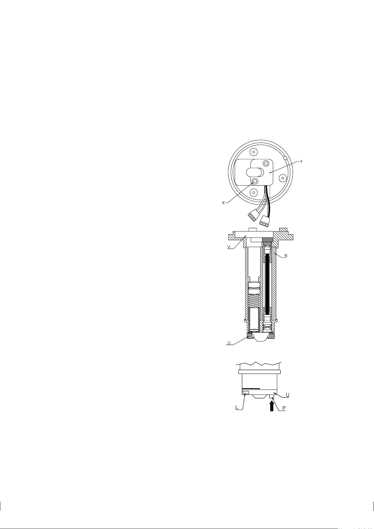
52 PR-03 instruction manual
8. Loosen carefully the six M4 screws (G) of the disc spring holder. Turn in small steps, alternating
between the screws.
Warning! Never touch the screws (G) when the instrument is in the line!
!
9. Remove the disc spring holder (H), the disc spring (J), and the thermal conductor (K).
6.4.2 Replacing the prism and prism gaskets
1. Lift out t he Core module, Figure 6.6 (a). The module does not turn
due to the alignment pin (R) Remove the Prism support (U) fixed by
two M3 screws (L), Figure 6.6 (b). Note: The temperature sensor (P)
restricts the movements of the Prism support (U).
2. To remove the prism, push it gently against the springs in the prism
plate (M), as indicated by an arrow in 6.3(a).
3. The LED assembly can now be removed by gently pulling the cable
(c), Figure 6.5.
4. Remove the connector (D) from the temperature sensor cable, Figure 6.5. Use a pointed tool to press on the small metal springs through
the openings at the flat side of the connector.
5. Now pull out the temperature sensor (P). Pull one lead a little fur ther
on than the other, to prevent the cable ends from plugging the hole.
6. To remove the lenses, loosen the two M2 screws (Z), Figure 6.7.
Warning! The lenses are springloaded.
!
7. Remove Prism plate (M) and Lens locking ring (under the Prism
plate).
8. Now the lenses, springs and lens spacers are free to be removed, Figure 6.6 (a).
9. Both end pieces of the Core module body are fixed with only one
screw each.
10. For assembly of the CORE module, use this procedure in reverse
order, then proceed to the sensor assembly instructions below.
Note: When mounting the temperature sensor (P) back again, do
not push it the whole way in. Leave leads visible, so that the Prism
support (U) can be mounted.
Note: When inserting the temperature sensor leads in the connector
(D), the middle hole in the connector should be empty.
11. Clean the prism. Important: Do not leave any finger prints on any of
the four optical surfaces!
(a)
(b)
Figure 6.6 The Core module
Page 59

6 Regular maintenance 53
12. Put the pr ism in place pushing gently against the springs of the prism plate (M). The direction of the
force is indicated by an arrow in Figure 6.7 (a). To make sure the prism is in correct position, press the
prism in the opposite direction of the arrow.
(a) (b)
Figure 6.7 The prism plate, the prism and prism gaskets
13. Put the prism support (U) upon the gasket. Keep the gasket in place with a fingertip in the middle.
Check that the gasket is symmetrical around the middle of the prism surface. Tighten the screws with
hemispherical heads (L) to the bottom, Figure 6.6 (b).
14. Push the temperature sensor (P) into its proper position. Mount the LED plate (Y). Check that the
temperature sensor (P) is properly springloaded. In outer position, the sensor tip is level with the prism
surface, Figure 6.6 (b). It should flex inwards 2-3 mm as indicated by an arrow, but return to the outer
position.
15. Now the CORE module is assembled. It should be checked before mounting into the sensor head:
a. Clean the window of the CCD-element (V), Figure 6.71 (a). Attach the Image detector card to the
Analyzer module by the two screws (F) with conical heads. Connect electrically all cards, with
connectors (A), (B), (C), and (D).
b. Connect the indicating transmitter, and inspect the optical image on Raw sensor data display, key
sequence Calibrate / Optical image.
c. The optical image must form a smooth curve. Dips or separate single points indicate that the optical
surfaces (e.g. the CCD window) are not clean. Important: The prism must be covered to exclude
external light.
d. When the image is OK, switch power off and disconnect all cards. Dismount the Image detector
card from the CORE module.
16. The Core module is now ready for sensor assembly.
Page 60

54 PR-03 instruction manual
6.4.3 Assembling the probe sensor
1. Fit the core module into the sensor head. Note the alignment pin (R), Figure 6.5.
2. Mount the thermal conductor (K) with the holes aligned to the screw holes.
Mount the disk spring (J). Note the position of the disk spring on the detail
(J), Figure 6.5.
3. Mount the disk spring holder (H). Fasten the six screws (G) in small steps
following the pattern of numbers in Figure 6.8. Continue until the holder
surface is flush with the surfaces of the three notches (S). No step should be
felt with the finger tip.
4. Mount the Image detector card with the screws (F), Figure 6.5. First tighten the two guiding screws with
conical heads, then the third screw. Lock the screws with e.g. nail polish.
5. Mount the Image digitizer card with the screws (E). Connect (B), (C) and (D).
Figure 6.8
Tightening the
spring holder screws
6. Check the dryer color, Figure 6.1. It should be yellow. If it is green, replace the dryer.
7. Place the sensor on a table with the prism upwards. Use a shar p knife with a curved edge to cut away
the circular piece of the gasket covering the prism. Warning! Support the knife on the prism surface
!
only as it will scratch the steel. Now the sensor is ready for process installation. Remember to check the
calibration (Section 5.10.1, “Checking current calibration”, and Appendix D, “Instrument verification
ISO 9000”).
Page 61

7 Troubleshooting and correcting problems 55
A
B
C
D
RAW
SENSOR
DATA
RMN: 2
RMX: 216
LED: 96
Scans: 2
A/D: 314
Sts: 00h
HT: 143
HH: 10
Scaled
image
Normal operation
7 Troubleshooting and correcting problems
7.1 Troubleshooting Indicating transmitter
Before investigating the sensor, it is advisable to make sure that the Indicating transmitter is working. The
Indicating transmitter can be tested separately from the sensor by the following procedure:
− Power off
− Disconnect cable to sensor
− Power on
Now the diagnostic message should be **No sensor signal**. If this is the case, the IT-R should
be in order. Power off, reconnect the cable to sensor, power on and continue to troubleshooting the sensor
(Section 7.2).
If the diagnostic message is anything else than **No sensor signal**, check Section 9.7 for the
message and required action.
Note: If the original diagnostic message was **Detector timeout**, the 15 V supply to the Image
detector card may be incorrect due to a wrong position of the power selector switch (Figures 3.8 and 3.9) on
the IT-R’s processor card. Check that the position of the power selector switch matches your power supply.
If the power selector switch is in the correct position, but the error message persists, the problem is in the
sensor, not in the IT-R (see below).
7.2 Troubleshooting sensor
The Calibrate branch of the command tree (Figure 9.5 contains a set of consequent displays that can be
used to troubleshoot sensor problems. Each display contains some important values than can give you clues
to where the problem might be.
7.2.1 LED value
Check the LED value that tells you how well the light passes through the optics. The LED value is given in
the Optical image display, available through the commands Calibrate / Optical image.
Figure 7.1 Checking the LED value
Page 62
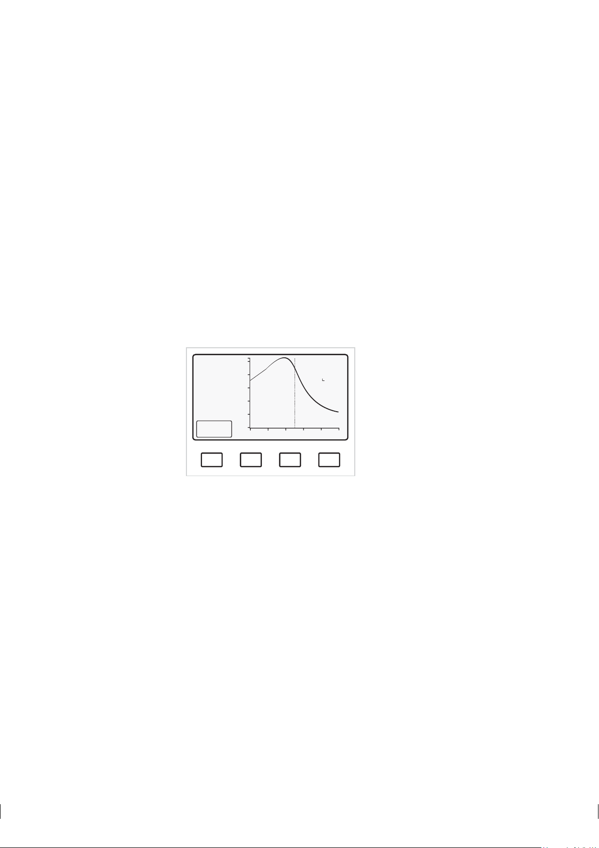
56 PR-03 instruction manual
A
B
C
D
SCALED
OPTICAL
IMAGE
TEST: 115.9
51.2 °C
Endp: 21
L): 9.8
R): 25.9
HT: 20 °C
HH: 3%
Slope
Normal operation
A good LED value is in the range 20-150. The most common reason to a LED value higher than 150 is
that prism is coated. It is also possible the prism has been destroyed with an overactive steam wash. Check
the wash times and the prism surface (especially if the wash time exceeds the maximum of 3 s). Replace
the prism if the surface is damaged (see Chapter 6 for instructions).
If the process is very hot, it is also possible that the light source LED wears out after many years’ constant
use and needs replacing. Also leakage into the sensor can destroy LEDs (and everything else inside the
sensor housing). However, normally the LEDs last as long as the sensor and high LED values indicate a
prism problem.
It is very unusual for the LED value to be lower than 20, but in theory this can be caused by light from
outside reaching the prism e.g. because the pipe is translucent.
7.2.2 Sensor temperature and humidity
Checking the conditions inside the sensor head will give you an idea whether there’s is a real physical
problem. The Scaled image (Calibrate / Optical image / Scaled image) shows you both
the internal sensor temperature and humidity.
Figure 7.2 Scaled image
The HT value gives you the sensor temperature and should be below 60◦C. If the value is over this limit,
the measurement may not be accurate and the sensor needs to be cooled more effectively, see Section 2.2.1.
The HH value gives the humidity level inside the sensor and should be lower than 10 %. Most commonly
a higher humidity level indicates a leak in the sensor. If the sensor is subjected to big temperature changes,
condensate can cause humidity problems. If this is the case, the problem can be solved by replacing the
dryer unit inside the sensor, see Section 6.1.
7.2.3 Slope value
The Slope display (Calibrate / Optical image / Scaled image / Slope) shows you
the slope image and also gives the Slope value as a number. A good slope value is above 1.5. If the slope
value drops near 1.0, something is wrong with the pr ism:
− Prism is coated or
− Prism surface is not good or
− Prism gaskets leak and process liquid gets in by the prism sides
Page 63

7 Troubleshooting and correcting problems 57
A
B
C
D
Diagnostics
SLOPE
TEST: 115.7
31.2 °C
Max: 208
Slope: 2.7
Endp: 21
L): 10.1
R(: 25.8
Normal operation
A
B
C
D
IMAGE DIAGNOSTICS
Max intensity OK (above 100)?
Endpoint below 75%?
Image below corner?
Slope OK (above 1)?
Left curve L) OK (above 1)?
Right curve R) OK (above 1)?
Yes
Yes
Yes
Yes
Yes
Yes
SENSOR HEAD
Head temperature: 28 °C
Head humidity: 3%
Normal operation.
A
B
C
D
A
B
C
D
IMAGE DIAGNOSTICS
Max intensity OK (above 100)?
Endpoint below 75%?
Image below corner?
Slope OK (above 1)?
Left curve L) OK (above 1)?
Right curve R) OK (above 1)?
Yes
Yes
No
No
Yes
No
SENSOR HEAD
Head temperature: 28 °C
Head humidity: 3%
Normal operation.
Figure 7.3 Slope display
Prism coating can be prevented by good process flow, high process temperature (see Section 2.2) or prism
wash. If your system already has prism wash, the wash interval can be decreased.
Important: The maximum wash times are given in Table 5.1. Do not exceed the recommended wash time,
instead you can try repeating the wash more often.
If prism surface is damaged, for example something in the process has abraded the pr ism or the wash time
has been long, replace the prism and adjust the prism wash or other conditions so that the prism doesn’t get
damaged.
If prism gaskets leak, replace them and all the sensor parts that have been damaged by the process liquid
inside the sensor (see Chapter 6, “Regular maintenance” for instructions).
7.2.4 Image diagnostics
The last tool in this branch of the selection tree is the Image diagnostics display, available through Calibrate / Optical image / Scaled image / Slope / Diagnostics. If the answer to
all the questions in this screen is Yes (Figure 7.4), the sensor head temperature and humidity are below the
limits and the message is Normal operation, your refractometer system should be in working order.
Note: If the system is offline, some of the image diagnostics questions will get No for an answer even in a
working system (Figure 7.4).
Inline image diagnostics (= process) Offline image diagnostics (= in air)
Figure 7.4 Image diagnostics display
Page 64

58 PR-03 instruction manual
IMAGE DIAGNOSTICS
Max intensity OK (above 100)?
Endpoint below 75%?
Image below corner?
Slope OK (above 1)?
Left curve L) OK (above 1)?
Right curve R) OK (above 1)?
Yes
Yes
Yes
Yes
Yes
Yes
SENSOR HEAD
Head temperature: 28 °C
Head humidity: 3%
Normal operation.
A
B
C
D
CONC
68.0%
PROCESS TEMPERATURE: 31.2 °C
STANDARD RI(25°C): 1.4194
TEST: 115.7
Normal operation
Calibrate
Display
A
B
C
D
A
B
C
D
CONC
PROCESS TEMPERATURE: 32.5 °C
STANDARD RI(25°C): 1.4190
TEST: 117.2
Normal operation
Optical
image
Parameters
68.0%
A
B
C
D
RAW
SENSOR
DATA
RMN: 2
RMX: 216
LED: 96
Scans: 2
A/D: 314
Sts: 00h
HT: 143
HH: 10
Scaled
image
Normal operation
A
B
C
D
SCALED
OPTICAL
IMAGE
TEST: 115.9
51.2 °C
Endp: 21
L(: 9.8
R): 25.9
HT: 20 °C
HH: 3%
Slope
Normal operation
Diagnostics
SLOPE
TEST: 115.7
31.2 °C
Max: 208
Slope: 2.7
Endp: 21
L): 10.1
R(: 25.8
Normal operation
A
B
C
D
Good LED value 20-150
Good slope value
more than 1.5
Good HT lower than 60 ºC
Good HH lower than 10 %
Figure 7.5 Troubleshooting your refractometer system with IT-R
Page 65

8 Sensor specifications and other sensor information 59
8 Sensor specifications and
other sensor information
8.1 Sensor labels
Sanitary refractometer label Process refractometer label
Figure 8.1 Examples of sensor labels
8.2 Sensor compatibility
The K-Patents Inline refractometer models PR-01 and PR-03 are not compatible with each other. The
interconnecting cable plug is the same for all the PR-03 models, but it is not compatible with the model
PR-01.
8.3 Sanitary refractometer PR-03-A
The 3-A approved Sanitary process refractometer for measuring Brix and concentrations in the pipe line.
Easy to install in any pipe size directly or via flow cell. The sanitary refractometer is well suited for all food
and beverage processing applications where on-line monitoring and control can help to improve product
quality and reduce costs.
Page 66

60 PR-03 instruction manual
8.3.1 PR-03-A sensor model code
MODEL AND DESCRIPTION MODEL
PR-03 = Sensor PR-03
Sensor classification
-A = 3-A approved -A
Refractive Index range limits
62 = R.I. 1.310–1.540 (0-100 Brix) 62
Process connection
-H = Sanitary 3-A clamp, 2 1/2 inch -H
Sensor wetted parts material
SS = AISI 316 L SS
Sensor options
-SC = Stainless steel sensor housing -SC
Example: Sensor: PR-03-A62-HSS
8.3.2 PR-03-A mounting hardware model code
Mounting hardware (without wash nozzles)
MODEL AND DESCRIPTION MODEL
EFC = Elbow flow cell EFC
Sensor connection
-H = Sanitary 3-A clamp, 2 1/2 inch -H
Construction material
SS = AISI 316 SS
Process connection
-H = Sanitary 3-A clamp -H
Pipe section diameter
10 = 25 mm (1 inch) (A) 10
15 = 40 mm (1 1/2 inch) 15
20 = 50 mm (2 inch) 20
25 = 65 mm (2 1/2 inch) (A) 25
Flow cell inlet type
-SI = Straight pipe -SI
-RI = Reduced pipe (cone) -RI
(A) with -SI option only
Page 67

8 Sensor specifications and other sensor information 61
Mounting hardware with wash nozzles
MODEL AND DESCRIPTION MODEL
EFC = Elbow flow cell EFC
Sensor connection
-H = Sanitary 3-A clamp, 2 1/2 inch -H
Construction material
SS = AISI 316 SS
Process connection
-H = Sanitary 3-A clamp -H
Pipe section diameter
10 = 25 mm (1 inch) (A) 10
15 = 40 mm (1 1/2 inch) (B) 15
20 = 50 mm (2 inch) 20
Flow cell inlet type
-SI = Straight pipe -SI
-RI = Reduced pipe (cone) -RI
Wash nozzle connection
-NC = Nozzle connection (B) -NC
Wash nozzles
-SN = Steam nozzle, PR-3365 -SN
-WN = Water nozzle, PR-3364 -WN
-WP = Pressurized water nozzle, PR-3366 (C) -WP
-PG = Plug for nozzle connection, PR-3367 -PG
(A) with -SI option only
(B) with -RI option only
(C) nozzle inlet R 1/2 inch female
Example: Sensor: PR-03-A62-HSS
Flow cell: EFC-HSS-H20-SI
MODEL AND DESCRIPTION MODEL
MFC = Mini flow cell MFC
Sensor connection
-H = Sanitary 3-A clamp, 2 1/2 inch -H
Construction material
SS = AISI 316 SS
Pipe section diameter
05 = 15 mm (1/2 inch) 05
Page 68

62 PR-03 instruction manual
1.30 1.35 1.40 1.45 1.50 1.55 1.60
R.I.
4001020 30 50
60
70 80 BRIX
A62
8.3.3 PR-03-A specifications
General specifications General system specifications for a PR-03-A refractometer sensor
Refractive index range R.I. 1.3100–1.5400 (hot water – 100 Brix)
Accuracy R.I. ± 0.0002 (corresponds typically to ± 0.1% by weight).
Repeatability and stability correspond to accuracy.
Speed of response 1.2 s undamped
Damping time constant Selectable up to 5 min
Process temperature -20◦C–130◦C (-4◦F–266◦F)
Temperature compensation Automatic
Ambient temperature max. 45◦C (113◦F), min. -20◦C (-4◦F)
Humidity 20–100 %
Pollution degree Degree 2
Process pressure Sanitary clamp max. 15 bar (200 psi) at 20◦C (70◦F)/
9 bar (125 psi) at 120◦C (250◦F)
Recommended flow velocity Above 1.5 m/s (5 ft/s)
Quality certificate ISO 9001
Sensor Meets the requirements of the 3-A Sanitary Standard 46-02
R
Wetted parts AISI 316L stainless steel, prism gaskets Teflon
, prism spinel
Sensor weight 2.2 kg (5 lbs)
Sensor protection class IP67, Nema 4X
Process connection 2 1/2" Sanitary clamp
Temperature measurement Built-in Pt-100
Image detector 1024 pixel CCD-element
Light source Light emitting diode (LED)
Indicating transmitter See Chapter 9
Options − External output unit, Section 4.2
− Relay units for prism wash/alarm, Section 4.1
− Prism wash nozzles for steam and hot water, Section 8.3.2
− Flow cells according to separate drawings available from K-Patents
− Stainless steel sensor housing
Figure 8.2 Sanitary refractometer PR-03-A rangeability
Page 69

8 Sensor specifications and other sensor information 63
8.3.4 PR-03-A parts lists
Item Pcs. Part No. Description
1 1 PR-9205 2.5"Sanitary ferrule
2 1 PR-9201 2.5"Sanitary clamp
3 1 PR-9202 2.5"Sanitary gasket EPDM
3 1 PR-9203 2.5"Sanitary gasket NBR
3 1 PR-9204 2.5"Sanitary gasket Teflon
4 1 PR-9002 PR-03 Head
5 1 Thermal insulator Teflon
6 1 Alignment pin
7 1 PR-03 Base
8 6 Screw M5x10 DIN 7991 A2
9 1 PR-9011 Thermal conductor
* 1 PR-9010 Disc spring set
10 2 Disc spring
11 1 Disc spring holder
12 6 Screw M4x8 DIN 912 A2
13 4 Screw M4x12 DIN
14 1 PR-7133 Image analyzer card
15 4 Screw M4x8 DIN 912 A2
16 1 PR-5012 Vee clamp 11-130
R
R
Item Pcs. Part No. Description
17 2 Screw M3x8 DIN 912
18 1 Bushing holder
19 1 Bushing
20 2 Screw M4x8 DIN 912 A2
21 2 Washer M4 DIN 125
22 1 PR-5011 O-ring seal 108x3
23 1 PR-9107 Dryer
24 2 Screw M3x16 DIN 912 A4
25 1 PR-9106 PR-03 Connector complete
26 1 PR-9110 PR-03 Cover
27 1 PR-03 Sensor label
28 4 Screw M3x5 DIN 7380 A4
39 1 PR-9001 CORE-Optics module
44 1 PR-7125 Image detector card
Page 70

64 PR-03 instruction manual
Item Pcs. Part No. Description
29 2 Screw M3x10 DIN 7380 A2
30 1 Prism support
* 1 PR-9004 H62 prism set
31 1 PR-9003 Prism gasket
32 1 H62 prism
33 2 Screw M2x5 DIN 965A A2
34 1 Prism plate
35 1 Lens locking r ing
36 1 Lens 8/30
37 2 Lens 8/10
38 2 Pressure spring 7.8x6
39 1 PR-9001 CORE optics module
40 1 PR-9250 PR-03 temperature element assembly
Item Pcs. Part No. Description
41 1 PR-9251 PR-03 LED assembly
42 1 LED plate
43 2 Screws M3x4 DIN 912
44 1 PR-7125 Image detector
45 2 Screw M3x10 DIN 7991 A2
46 1 Screw M3x10 DIN 912 A2
Page 71

8 Sensor specifications and other sensor information 65
8.3.5 PR-03-A mounting specifics
K-Patents Sanitary refractometer PR-03 is connected to the process by a 2 1/2" 3-A sanitary clamp. The
recommended mounting is in a pipe bend, with a vertical flow upwards before the sensor, and a horizontal
pipe after. The benefits of this way of mounting are:
1. Self-cleaning of prism due to the flow directed against its surface.
2. Efficient drainage when the pipe is emptied.
For pipe diameters of 3" or above, a ferrule is welded directly to the pipe wall, Figure 8.3 (a ferrule, length
21.5 mm, is delivered with standard sensor delivery from K-Patents). For smaller pipe diameters, flow cells
are available from K-Patents, Figures 8.4, 8.5 and 8.6, see also the tables in Section 8.3.2. The inlet of the
flow cells is coned down to obtain a good flow velocity against the prism. The flow cells are exchangeable
with standard 90◦bend pieces.
Figure 8.3 Mounting with sanitary ferrule (Pipe diameter 3" (80 mm) or larger)
Page 72

66 PR-03 instruction manual
Figure 8.4 Flow cell EFC-HSS-H25-SI (Pipe diameter 2 1/2" (65 mm))
Figure 8.5 Flow cell EFC-HSS-H20-RI (Pipe diameter 2" (50 mm))
Page 73

8 Sensor specifications and other sensor information 67
Figure 8.6 Flow cell EFC-HSS-H15-RI (Pipe diameter 1 1/2" (40 mm))
If a Sanitary refractometer sensor PR-03-A is to be installed in a sample line, diameter 5-10mm, it is
mounted with a mini flow cell, Figure 8.7.
Figure 8.7 PR-03-A mini flow cell
Page 74

68 PR-03 instruction manual
8.4 Probe refractometer PR-03-P
The K-Patents Probe refractometer PR-03-P-V/P provides an accurate on-line BRIX measurement in cookers, tanks and large pipelines. Some sensor options allow flush mounting in a tank wall and thus make it
possible to use a scraper. With certain options the Probe refractometer can also be installed in a cooker
through a steam jacket.
8.4.1 PR-03-P sensor model code
MODEL AND DESCRIPTION MODEL
PR-03 = Sensor PR-03
Sensor classification
-P = 3-A Sanitary Probe -P
Refractive Index range limits
62 = R.I. 1.310–1.540 (0-100 Brix) 62
Process connection
-T = Sanitary 3-A clamp, 2 1/2 inch, insertion length 139.5 mm -T
-R = Sanitary 3-A clamp, 4 inch, insertion length 139.5 mm -R
-V = Sanitary 3-A clamp, 2 1/2 inch, flush mounted (B) -V
-P = MT4 DN 25/1T APV Tank bottom flange, flush mounted -P
Sensor wetted parts material
SS = AISI 316 L SS
Sensor options (A)
-SC = Stainless steel sensor housing -SC
-PC = Adapted for air purging -PC
(A) For standard sensor, leave this section blank
(B) Needs vessel flush mount adaptor VFMA-03-VSS
Table 8.1 PR-03-P model code
8.4.2 PR-03-P mounting hardware model code
MODEL AND DESCRIPTION MODEL
VFMA-03-VSS = vessel flush mount adaptor for PR-03-P62-VSS VFMA-03-VSS
VFMA-03-PSS = MT4 DN25/1T APV tank bottom flange for PR-03-P62-PSS VFMA-03-PSS
VFBP-03-VSS = Blind plug for vessel flush mount adaptor VFMA-03-VSS VFBP-03-VSS
Page 75

8 Sensor specifications and other sensor information 69
8.4.3 PR-03-P specifications
General specifications General system specifications for a PR-03-P refractometer sensor
Refractive Index range R.I. 1.3100–1.5400 (corresponds to hot water–100 Brix)
Accuracy R.I. ± 0.0002 (corresponds typically to ± 0.1% by weight).
Repeatability and stability correspond to accuracy.
Speed of response 1.2 s undamped
Damping time constant Selectable up to 5 min
Process temperature -20◦C–130◦C (-4◦F–266◦F)
Temperature compensation Automatic
Ambient temperature max. 45◦C (113◦F), min. -20◦C (-4◦F)
Humidity 20–100 %
Pollution degree Degree 2
Process pressure Sanitary clamp max. 15 bar (200 psi) at 20◦C (70◦F)/
9 bar (125 psi) at 120◦C (250◦F)
Recommended flow velocity Above 1.5 m/s (5 ft/s)
Quality certificate ISO 9001
Sensor Meets the requirements of the 3-A Sanitary Standard 46-02
R
Wetted parts AISI 316L stainless steel, prism gaskets Teflon
, prism spinel
Sensor weight 2.4 kg (5.3 lbs)
Sensor protection class IP67, Nema 4X
Process connections 2 1/2" Sanitary clamp
4" Sanitary clamp
MT4 DN 25/1T APV Tank bottom flange
Temperature measurement Built-in Pt-100
Image detector 1024 pixel CCD-element
Light source Light emitting diode (LED)
Indicating transmitter See Chapter 9
Options − External output unit, Section 4.2
− Relay units, Section 4.1
− Stainless steel sensor housing
Page 76
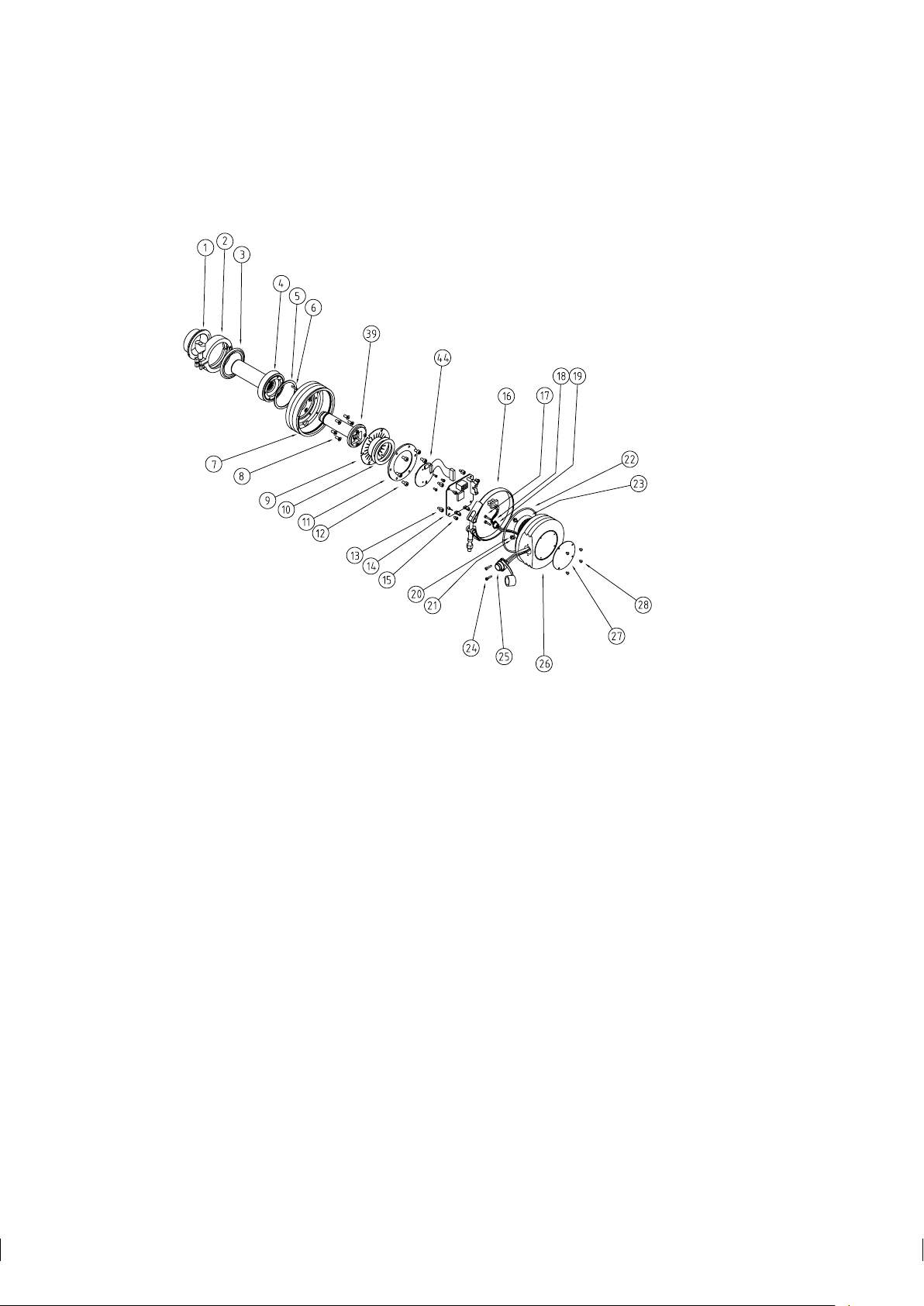
70 PR-03 instruction manual
8.4.4 PR-03-P parts lists
Item Pcs. Part No. Description
1 1 PR-9205 2.5"sanitary ferrule
1 1 VFMA-03-VSS Vessel flush mount adaptor
1 1 VFMA-03-PSS MT4 DN25/1T APV tank bottom flange
1 1 VFBP Blind plug for tank bottom flange
1 1 PR-4275 4"sanitary ferrule
2 1 PR-9201 2.5"sanitary clamp
2 1 PR-9270 4"sanitary clamp
3 1 PR-9202 2.5"sanitary gasket EPDM
3 1 PR-9203 2.5"sanitary gasket NBR
3 1 PR-9204 2.5"sanitary gasket Teflon
3 1 PR-9243 MT4 DN25/1T APV gasket EPDM
3 1 PR-9272 4"3A sanitary gasket EPDM
3 1 PR-9273 4"3A sanitary gasket NBR
3 1 PR-9274 4"3A sanitary gasket Teflon
4 1 PR-9310 PR-03-P-TSS head
4 1 PR-9311 PR-03-P-VSS head
4 1 PR-9312 PR-03-P-PSS head
4 1 PR-9313 PR-03-P-RSS head
5 1 Thermal insulator Teflon
6 1 Alignment pin
7 1 PR-9005 PR-03 base
8 6 Screw M5x10 DIN 7991 A2
9 1 PR-9011 Thermal conductor
R
R
R
Item Pcs. Part No. Description
* 1 PR-9010 Disc spring set
10 2 Disc spring
11 1 Disc spring holder
12 6 Screw M5x10 DIN912 A2
13 4 Screw M4x12 DIN
14 1 PR-7133 Image digitizer card
15 4 Screw M4x8 DIN 912 A2
16 1 PR-5012 Vee clamp 11-130
17 2 Screw M3x8 DIN 912
18 1 Bushing holder
19 1 Bushing
20 2 Screw M4x8 DIN 912 A2
21 2 Washer M4 DIN 125
22 1 PR-5011 O-ring seal 108x3
23 1 PR-9107 Dryer
24 2 Screw M3x16 DIN 912 A4
25 1 PR-9106 PR-03 connector complete
26 1 PR-9301 PR-03 cover
27 1 PR-03 sensor label
28 4 Screw M3x5 DIN 7380 A4
Page 77

8 Sensor specifications and other sensor information 71
Item Pcs. Part No. Description
29 2 Screw M3x20 DIN 7380 A2
30 1 Prism support
* 1 PR-9004 H62 prism set
31 1 PR-9003 Prism gasket
32 1 H62 prism
33 2 Screw M2x5 DIN 965A A2
34 1 Prism plate
35 1 Lens locking r ing
36 1 PR-03-P lens assembly
37 2 Lens 8/10
38 2 Pressure spring 7.8x6
39 1 PR-9301 PR-03-P CORE Optics module
40 1 PR-9255 PR-03-P temperature element assembly
Item Pcs. Part No. Description
41 1 PR-9256 PR-03-P LED assembly
42 1 LED plate
43 2 Screws M3x12 DIN 912 A2
44 1 PR-7125 Image detector
45 2 Screw M3x10 DIN 7991 A2
46 1 Screw M3x10 DIN 912 A2
47 1 Pressure spring 9.8x25
48 1 Lens ring
49 1 Screw M3x12 DIN 912 A2
49 1 Screw M3x12 DIN 912 A2
50 2 Lens 10/50
51 1 Screw M3x10 DIN 7991 A2
Page 78

72 PR-03 instruction manual
4-20 mA
~
CHECK CABLE LENGTH
8.4.5 PR-03-P mounting specifics
The Probe refractometer PR-03-P is primarily designed for mounting in a tank wall. To ensure that the
measurement is representative and that the prism stays clean, the probe should be installed close to a stirrer,
Figure 8.8.
Figure 8.8 Recommendations for mounting the Probe sensor PR-03-P in a t ank
K-Patents probe refractometer type PR-03-P62-TSS is connected to the process by a 2 1/2" 3-A sanitary
clamp, Figure 8.9. The type PR-03-P62-RSS type sensor is connected to process by a 4" 3-A sanitary
clamp.
Note: For higher process (or ambient) temperatures, use instead a flush mounted sensor (Figures 8.9, 8.10
and 8.11), where the electronics in the sensor head are further away from the process heat.
Figure 8.9 Insertion of Probe refractometer PR-03-P62-TSS
Page 79

8 Sensor specifications and other sensor information 73
Figure 8.10 Flush mounted Probe refractometer PR-03-P62-PSS
The refractometer type PR-03-P62-PSS is flush mounted, using a sanitary APV Tank bottom flange, Figure 8.10. The refractometer can be replaced with a blind plug so that the tank can be used even when the
refractometer has been removed for service.
The refractometer type PR-03-P62-VSS is specially designed for vessels with a steam jacket, e.g. a jam
cooker. In a jam cooker the blade of the scraper should sweep the prism in direct contact. The PR-03-P62-
VSS is mounted by means of a vessel flush-mount adaptor VFMA-03-VSS, Figure 8.11.
Figure 8.11 Mounting probe refractometer PR-03-P62-VSS
through vessel steam jacket with adaptor VFMA-03-VSS
Page 80

74 PR-03 instruction manual
A
B
C
D
Slope
TEST: 248.0
30.2 ºC
Endp: 11
L): -7.5
R(: 3.3
HT: 20 ºC
HH: 4 %
SCALED
OPTICAL
IMAGE
Low concentration / No sample
8.4.6 PR-03-P programming specifics
If the optical image appears inverted when using the probe refractometer PR-03-P (see Figure 8.12), configure parameter lminv to value 1 by key-in sequence Calibrate / Parameters / Standard RI
(25◦C) / Image inversion to turn the picture right way.
Figure 8.12 Inverted optical image
Note: This image inversion correction is only available in program version 8.5 or higher. When an IT-R
is delivered together with a Probe refractometer sensor, the program version is always compatible with the
inverted image.
Page 81

8 Sensor specifications and other sensor information 75
8.5 Compact process refractometer PR-03-D
The K-Patents Compact process refractometer is a compact general industry model for measuring liquid
concentrations in various in-line applications, like chemicals, fibers, plastics, salts and sodium components.
Easy to install in smaller pipe lines. Also for applications where special alloys are required.
8.5.1 PR-03-D sensor model code
MODEL AND DESCRIPTION MODEL
PR-03 = Sensor PR-03
Sensor classification
-D = General purpose -D
Refractive Index range limits
62 = R.I. 1.310–1.540 (0-100 Brix) 62
Process connection
-L = Sandvik L clamp, 76.1 (A) -L
Sensor wetted parts material
SS = AISI 316 L SS
HC = Hastelloy C / ASTM C276 HC
TI = Titanium / ASTM B TI
NI = Nickel 200 NI
Sensor options (B)
-SC = Stainless steel sensor housing -SC
-PC = Adapted for Exproof by purging (C) -PC
(A) Includes counter ferrule for Sandvik 76.1
(B) For standard sensor without option, leave this section blank
(C) Available with -SC code only, including 5 meters sensor cable, PR-8400-005
Example: Sensor: PR-03-D62-LSS
8.5.2 PR-03-D mounting hardware model code
MODEL AND DESCRIPTION MODEL
PFC = Pipe flow cell PFC
Sensor connection
-L = Sandvik L clamp -L
Construction material
SS = AISI 316 SS
Process connection
-A = ANSI 150 psi -A
Pipe section diameter
10 = 25 mm (1 inch) 10
For line sizes 76 mm (2 1/2 inch) or bigger use standard process connections.
Page 82

76 PR-03 instruction manual
1.30 1.35 1.40 1.45 1.50 1.55 1.60
R.I.
4001020 30 50
60
70 80 CONC%
D62
8.5.3 PR-03-D specifications
General specifications General system specifications for a PR-03-D refractometer sensor
Refractive Index range R.I. 1.3100–1.5400 (corresponds to hot water–100 Conc% b.w.)
Accuracy R.I. ± 0.0002 (corresponds typically to ± 0.1% by weight).
Repeatability and stability correspond to accuracy.
Speed of response 1.2 s undamped
Damping time constant Selectable up to 5 min
Process temperature -20◦C–130◦C (-4◦F–266◦F)
Temperature compensation Automatic
Ambient temperature max. 45◦C (113◦F), min. -20◦C (-4◦F)
Humidity 20–100 %
Pollution degree Degree 2
Process pressure max. 15 bar (200 psi) at 20◦C (70◦F)/
9 bar (125 psi) at 120◦C (250◦F)
Recommended flow velocity Above 1.5 m/s (5 ft/s)
Quality certificate ISO 9001
Sensor
R
Wetted parts AISI 316L stainless steel, prism gaskets Teflon
, prism spinel
Optional wetted parts Hastelloy C/ASTM C276, Titanium/ASTM B 348 GR2, Nickel 200
Sensor weight 2 kg (4.4 lbs)
Sensor protection class IP67, Nema 4X
Process connection Sandvik L clamp 76.1 mm (2 1/2")
Temperature measurement Built-in Pt-100
Image detector 1024 pixel CCD-element
Light source Light emitting diode (LED)
Indicating transmitter See Chapter 9
Options − External output unit, Section 4.2
− Relay units for prism wash/alarm, Section 4.1
− Stainless steel sensor housing
Figure 8.13 Compact process refractometer PR-03-D rangeability
Page 83

8 Sensor specifications and other sensor information 77
8.5.4 PR-03-D parts lists
Item Pcs. Part No. Description
1 1 PR-9280-SS Sandvik ferrule 76.1 AISI 316L
1 1 PR-9280-HC Sandvik ferrule 76.1 Hastelloy
1 1 PR-9280-TI Sandvik ferrule 76.1 Titanium
1 1 PR-9280-NI Sandvik ferrule 76.1 Nickel
2 1 PR-9282 Sandvik clamp FCLC-76.1 AISI 304
3 1 PR-9281 Sandvik O-ring FCLG-T-76.1 Teflon
4 1 PR-9009 PR-03 Sandvik 76.1 head
5 1 Thermal insulator Teflon
6 1 Alignment pin
7 1 PR-9005 PR-03 base
8 6 Screw M5x10 DIN 7991 A2
9 1 PR-9011 Thermal conductor
* 1 PR-9010 Disc spring set
10 2 Disc spring
11 1 Disc spring holder
12 6 Screw M5x10 DIN 912 A2
13 4 Screw M4x12 DIN 912
14 1 PR-7133 Image digitizer
15 4 Screw M4x8 DIN 912 A2
16 1 PR-9001 CORE optics module
17 1 PR-5012 Vee clamp 11-130
R
registered
Item Pcs. Part No. Description
18 2 Screw M3x8 DIN 912
19 1 Bushing holder
20 1 Bushing
21 1 PR-7125 Image detector card
22 2 Screw M4x8 DIN 912 A2
23 2 Washer M4 DIN 125
24 1 PR-5011 O-ring seal 108x3
25 1 PR-9107 Dryer
26 2 Screw M3x16 DIN 912 A4
27 1 PR-9106 PR-03 connector complete
28 1 PR-9110 PR-03 sensor cover
29 1 PR-03 sensor label
30 4 Screw M3x5 DIN 7380 A4
Page 84

78 PR-03 instruction manual
Item Pcs. Part No. Description
29 2 Screw M3x10 DIN 7380 A2
30 1 Prism support
30 1 Prism support H64
31 1 PR-9003 Prism gasket (PTFE)
32 1 PR-9004 H62 prism set (Spinel)
33 2 Screw M2x5 DIN 965A A2
34 1 Prism plate
35 1 Lens locking r ing
36 1 Lens
37 1 Lens 8/10
38 2 Pressure spring 7.8x6
39 1 PR-9001 CORE optics module
40 1 PR-9250 PR-03 temperature element assembly
Item Pcs. Part No. Description
41 1 PR-9251 PR-03 LED assembly
42 1 LED plate
43 2 Screws M3x4 DIN 912
44 1 PR-7125 Image detector card
45 2 Screw M3x10 DIN 7991 A2
46 1 Screw M3x10 DIN 912 A2
Page 85

8 Sensor specifications and other sensor information 79
8.5.5 PR-03-D mounting specifics
In pipes with the nominal size 2.5" (76.1mm) or larger, the Compact process refractometer PR-03-D sensor
is mounted with a Sandvik-L 76.1 clamp, Figure 8.14. For smaller pipes, the sensor has to be mounted with
the PFC Pipe Flow cell, Figure 8.15.
Figure 8.14 Mounting PR-03-D in pipelines with diameter 2.5" (76.1 mm) or larger
Page 86

80 PR-03 instruction manual
Figure 8.15 Mounting PR-03-D in pipelines with diameter less than 2.5" (76.1mm)
Page 87

8 Sensor specifications and other sensor information 81
8.6 Process refractometer PR-03-M
K-Patents Process refractometer PR-03-M is designed for use in chemically aggressive solutions
and ultra-pure fine chemical processes. It has a
built-in flow cell designed to keep all metal and
other easily corroding parts from coming into contact with the process liquid. All the wetted parts
are made of non-metallic materials, either PTFE
(Teflon
PR-03-M sensor withstands corrosion very well.
The flow cell (N) and the sapphire plate (L) are
fixed to the stainless steel sensor with four screws.
The flow cell (N) is sealed by a Kalrez O-ring
(M). The flow cell prevents any leakage reaching
the metal parts, because there is a circular leakage
chamber behind the O-ring (M). The chamber connects to a check port (O), which has a 1/8" female
thread connection.
R
) or PVDF (Kynar
R
), and thus the
Figure 8.16 PR-03-M sensor
8.6.1 PR-03-M sensor model code
MODEL AND DESCRIPTION MODEL
PR-03 = Sensor PR-03
Sensor classification
-M = Aggressive medium adapter -M
Refractive Index range limits
62 = 1.310–1.540 R.I. (0.100 Conc% b.w.), Spinel prism 62
74 = 1.260–1.500 R.I., sapphire prism 74
Process line connection
-R = Thread (G 1/2 inch) -R
-N = Thread (1/2 inch NPT female) -N
Line size connection diameter
-050 = 1/2 inch (flow volume 2-8 l/min (0.5-2.1 GPM)) -050
Flow cell wetted par ts material
-PV = Kynar
-TF = Teflon
Sensor cover
-SC = Stainless Steel sensor housing -SC
(A) including 5 meter sensor cable, PR-8400-005
Example: Sensor: PR-03-M62-R-050-TF-SC
R
(PVDF=Polyvinylidenefluoride) -PV
R
(PTFE=Polytetrafluoroethylene) -TF
Sensor options
-PC = adapted for Exproof by purging (A) -PC
Page 88

82 PR-03 instruction manual
1.30
1.25
1.35 1.40 1.45 1.50 1.55 1.60
1.65
R.I.
40010 20 30 50
60
70 80 BRIX
M62
M74
8.6.2 PR-03-M specifications
General specifications General system specifications for a PR-03-M refractometer sensor
Refractive Index range, standard R.I. 1.3100–1.5400 (corresponds to hot water–100 Brix) with
spinel prism
Refractive Index range R.I. 1.2600–1.5000 with sapphire prism
Refractive Index range R.I. 1.3900–1.6200 with YAG prism
Accuracy R.I. ± 0.0002 (corresponds typically to ± 0.1% by weight).
Repeatability and stability correspond to accuracy.
Speed of response 1.2 s undamped
Damping time constant Selectable up to 5 min
Process temperature -20◦C–130◦C (-4◦F–212◦F)
Temperature compensation Automatic
Ambient temperature max. 45◦C (113◦F), min. -20◦C (-4◦F)
Humidity 20–100 %
Pollution degree Degree 2
Process pressure max 5 bar (72.5 psi)
Recommended flow velocity 2–40 l/min (0.5–10.6 GPM)
Protected by the following US Patent Patent No. US6067151
Sensor
Wetted parts, standard Teflon
R
or Kynar
R
PVDF, prism gaskets Teflon
O-ring Kalrez, adaptor sapphire
Wetted parts, option prism sapphire or YAG
Sensor weight 5.5 kg (12.1 lbs)
Sensor protection class IP67, Nema 4X
Process connection Thread G1/2" (F)
Temperature measurement Built-in Pt-100
Image detector 1024 pixel CCD-element
Light source Light emitting diode (LED)
Sensor housing AISI 316L stainless steel sensor cover
Exproof Exproof by purging
Indicating transmitter see page See Chapter 9
Options − External output unit, Section 4.2
− Relay units for alarm, Section 4.1
R
, prism spinel,
Figure 8.17 Process refractometer PR-03-M rangeability
Page 89

8 Sensor specifications and other sensor information 83
8.6.3 PR-03-M parts lists
Item Pcs. Part No. Description
1 4 Screw M5x60 DIN 7991 A4
2 1 PR-03-M endplate
3 1 PR-9120 PR-03-M-PV-R05 flow cell (PVDF)
3 1 PR-9121 PR-03-M-TF-R05 flow cell (PTFE)
4 1 PR-9240 O-ring seal 19.2 x 3 Kalrez 4079
5 6 Screw M4 x 20 DIN 7991 A4
6 1 PR-03-M Headring (PVDF)
7 1 PR-9112 O-ring seal 30.3 x 2.4 FPM
8 1 PR-9122 Sapphire plate for PR-03-M
9 1 PR-9113 O-ring seal 37.3 x 3 FPM
10 1 PR-9100 Sensor support
11 1 PR-9102 PR-03-M head
12 1 Thermal insulator (Teflon
13 1 Alignment pin
14 1 PR-9005 PR-03 base
15 6 Screw M5x10 DIN 7991 A2
16 1 PR-9001 CORE optics module
16 1 PR-9101 CORE 74 optics module
17 1 PR-9011 Thermal conductor
* 1 PR-9010 Disc spring set
18 2 Disc spring
19 1 Disc spring holder
20 6 Screw M5x10 DIN 912 A2
21 1 PR-7125 Image detector card
22 4 Screw M4x12 DIN
23 1 PR-7133 Image digitizer
24 4 Screw M4x8 DIN 912 A2
25 1 PR-5012 Vee clamp 11-130
R
)
Item Pcs. Part No. Description
26 2 Screw M3x16 DIN 912 A4
27 1 Bushing holder
28 1 Bushing
29 1 PR-5011 O-ring seal 108x3
30 1 PR-9107 Dryer
31 2 Screw M4x8 DIN 912 A2
32 2 Washer M4 DIN 125
33 2 Screw M3x8 DIN 912
34 1 PR-9106 PR-03 connetor complete
35 1 PR-9110 PR-03 cover
36 1 PR-03 sensor label
37 4 Screw M3x5 DIN A4
Page 90

84 PR-03 instruction manual
Item Pcs. Part No. Description
38 2 Screw M3x10 DIN 7380 A2
39 1 Prism support
39 1 Prism support H64
* 1 PR-9004 H62 prism set (Spinel)
40 1 PR-9003 Prism gasket (PTFE)
41 1 H62 prism (Spinel)
* 1 PR-9104 H74 prism set (Sapphire)
40 1 PR-9003 Prism gasket (PTFE)
41 1 H74 prism (Sapphire)
42 2 Screw M2x5 DIN 965A A2
43 1 Prism plate
44 1 Lens locking ring
45 1 Lens
46 2 Lens 8/10
47 2 Pressure spring 7.8x6
48 1 PR-9250 PR-03 temperature element assembly
Item Pcs. Part No. Description
49 1 PR-9251 PR-03 LED assembly
50 1 LED plate
51 2 Screws M3x4 DIN 912
21 1 PR-7125 Image detector card
52 2 Screw M3x10 DIN 7991 A2
53 1 Screw M3x10 DIN 912 A2
Page 91

8 Sensor specifications and other sensor information 85
3
PTFE or PVDF wetted parts
Sapphire plate
O-ring (Kalrez)
Prism
Flow cell adapter
(AISI 316L)
Graphite cast iron
Saunders valve body flow cell
F
L
O
W
PR-03-W Sensor
8.6.4 PR-03-M mounting specifics
K-Patents Process refractometer PR-03-M is connected to the process by a G1/2" female or a 1/2" NPT
process connection, Figure 8.18.
Figure 8.18 G1/2" female process connection (mm [in])
8.7 Valve body refractometer PR-03-W
The Valve body refractometer PR-03-W
is a heavy-duty instrument designed for
chemically aggressive liquids and ultrapure fine chemicals in large-scale pro-
duction and in large pipelines. The materials and design of the sensor are similar to the Process refractometer PR-03M, but the valve body makes it possible to fit this refractometer into 50, 80
or 100 mm (2", 3" or 4") pipelines.
The valve body material is graphite cast
iron lined with 3 mm PFA (Fluorinated
ethylene propylene) fluoroplastic. The
cast iron provides a solid mechanical
base and the PFA lining ensures the
chemical resistance.
The sensor itself is built just like the PR-03-M sensor (see Section 8.6) and it is fixed to the valve body in
the same way, with a sapphire plate and a Kalrez O-ring to keep all the metallic parts away from the process
liquid.
Figure 8.19 PR-03-W sensor
Page 92

86 PR-03 instruction manual
8.7.1 PR-03-W sensor model code
MODEL AND DESCRIPTION MODEL
PR-03 = Sensor PR-03
Sensor classification
-W = Aggressive medium valve body flow cell -W
Refractive Index range limits
62 = 1.310–1.540 R.I., Spinel prism (0-100 Conc% b.w.) 62
74 = 1.260–1.500 R.I., sapphire prism 74
Sensor wetted parts material
-PV = Kynar
-TF = Teflon
Sensor/diaphragm valve body connection
4 = Adapter for 4 inch/DN 100 valve body 4
3 = Adapter for 3 inch/DN 80 valve body 3
2 = Adapter for 2 inch/DN 50 valve body 2
(A) Including 5 meter sensor cable, PR-8400-005
R
(PVDF=Polyvinylidenefluoride) -PV
R
(PTFE=Polytetrafluoroethylene) -TF
Sensor cover
-SC = stainless steel sensor housing -SC
Sensor classification
-GP = General purpose, Nema 4X -GP
-PC = Adapted for Exproof by purging(A) -PC
SAUNDERS VALVE BODY FOR SENSOR PR-03-W MODEL
SVB = Saunders valve body SVB
Process line connection
-A040 = ANSI flange 4 inch 150 lbs -A040
-A030 = ANSI flange 3 inch 150 lbs -A030
-A020 = ANSI flange 2 inch 150 lbs -A020
-D100 = DIN flange DN 100 PN 16 -D100
-D080 = DIN flange DN 80 PN 16 -D080
-D050 = DIN flange DN 50 PN 16 -D050
Valve body material
-GC = Graphite cast iron -GC
Valve body lining material
-PFA = PFA (= Fluorinated ethylene propylene) -PFA
Page 93

8 Sensor specifications and other sensor information 87
8.7.2 PR-03-W specifications
General specifications General system specifications for a PR-03-W refractometer sensor
Refractive index range, standard R.I. 1.3100–1.5400 (corresponds to hot water–100 Conc% b.w.) with
spinel prism
Refractive index range, option R.I. 1.2600–1.5000 with sapphire prism
Accuracy R.I. ± 0.0002 (corresponds typically to ± 0.1% by weight).
Repeatability and stability correspond to accuracy.
Speed of response 1.2 s undamped
Damping time constant Selectable up to 5 min
Process temperature -20◦C–100◦C (-4◦F–212◦F)
Temperature compensation Automatic
Ambient temperature max. 45◦C (113◦F), min. -20◦C (-4◦F)
Humidity 20–100 %
Pollution degree Degree 2
Process pressure max. 10 bar (145 psi)
Recommended flow velocity 1.5–6 m/s
Protected by US Patent No. US6067151, German Patent No. DE19855218
Sensor
Wetted parts, standard Teflon
R
PTFE, prism gasket Teflon
R
PTFE, prism spinel or sapphire,
O-ring Kalrez, adaptor sapphire
Sensor weight With 2” Saunders body 15 kg (33 lbs)/3” Saunders body 26 kg
(57 lbs)/4” Saunders body 33 kg (73 lbs)
Sensor protection class IP67, Nema 4X
Process connection With PFA (Fluorinated ethylene propylene) lined Saunders valve body
2", 3" or 4"
Temperature measurement Built-in Pt-100
Image detector 1024 pixel CCD-element
Light source Light emitting diode (LED)
Sensor housing AISI 316L stainless steel cover
Exproof Exproof by purging
Saunders valve body
Valve body material Graphite cast iron
Valve body lining material PFA (Fluorinated ethylene propylene)
Process connection ANSI flange 4 inch 150 lbs / ANSI flange 3 inch 150 lbs /
ANSI flange 2 inch 150 lbs / DIN flange DN 100 PN 16 /
DIN flange DN 80 PN 16 / DIN flange DN 50 PN 16
Indicating transmitter See Chapter 9
Options − External output unit, Section 4.2
− Relay units for alarm, Section 4.1
Page 94

88 PR-03 instruction manual
8.7.3 PR-03-W parts lists
Item Pcs. Part No. Description
1 4 Screw M5x60 DIN 7991 A4
3 1 Saunders valve body PFA lining ANSI 2“/DIN 50
3 1 Saunders valve body PFA lining ANSI 3“/DIN 80
3 1 Saunders valve body PFA lining ANSI 4“/DIN 100
4 1 PR-9240 O-ring seal 19.2 x 3 Kalrez 4079
5 6 Screw M4 x 20 DIN 7991 A 4
6 1 Spacer
7 1 PR-9112 O-ring seal 30.3 x 2.4 FPM
8 1 PR-9122 Sapphire plate for PR-03-M
9 1 PR-9113 O-ring seal 37.3 x 3 FPM
10 1 PR-03-M Headring (PVDF)
11 1 PR-9102 PR-03-W head
12 1 Thermal insulator Teflon
13 1 Alignment pin
14 1 PR-9005-SC PR-03 base SS
15 6 Screw M5x10 DIN 7991 A2
16 1 PR-9011 Thermal conductor
* 1 PR-9010 Disc spring set
17 2 Disc spring
18 1 Disc spring holder
R
Item Pcs. Part No. Description
19 6 Screw M5x10 DIN912 A2
20 4 Screw M4x12 DIN
21 1 PR-7133 Image digitizer
22 4 Screw M4x8 DIN 912 A2
23 1 PR-5012 Vee clamp 11-130
24 2 Screw M3x8 DIN 912
25 1 Bushing holder
26 1 Bushing
27 2 Screw M4x8 DIN 125
28 2 Washer M4 DIN 912 A2
29 1 PR-5011 O-ring seal 108x3
30 1 PR-9107 Dryer
31 2 Screw M3x16 DIN 912 A2
32 1 PR-9106 PR-03 connector complete
33 1 PR-9110-SC PR-03 cover
34 1 PR-03 sensor label
35 4 Screw M3x5 DIN 7380 A4
39 1 PR-9001 CORE optics module
39 1 PR-9101 CORE 74 optics module
44 1 PR-7125 Image detector card
Page 95

8 Sensor specifications and other sensor information 89
8.7.4 PR-03-W mounting specifics
PR-03-W Saunders valve body flow cell can be mounted either vertically or horizontally. Special sensor
support is not needed as t he valve body (piping) supports the sensor. Either way sensor cover should always
be horizontal to avoid sedimentation or gas/air pocket on the prism. Also installation after pump, before
valve and low installation point will reduce risk of air/gas pocket. Recommended flow velocity is 1.5–6m/s
(6–20ft/s).
Page 96

90 PR-03 instruction manual
Page 97

9 Indicating transmitter specifications 91
PROCESS REFRACTOMETER
IT-RE-GP S/N:00Z25-4129
100 - 115/220 - 240 V AC, 50/60 Hz, 20VA
TAG:
9 Indicating transmitter specifications
9.1 IT-R label
Figure 9.1 Indicating transmitter serial number label
Serial number should match the serial number on sensor head
9.2 IT-R compatibility
An Indicating transmitter can be exchanged for another of the same model, but the current calibration
constants have then to be entered by the keyboard (Section 5.10) as your IT-R has been precalibrated for the
process it was ordered for.
The models PR-03 and PR-01 use the same Indicating transmitter. When the power is switched on, the
microprocessor checks which sensor model is connected, and adapts the software accordingly.
Note: The plug at the sensor end is different for PR-03 and PR-01. All PR-03 models use same electrical
connector and cables.
9.2.1 U pg rading IT-R program version
The program version number consists of two digits. The first digit is the major version, the latter is the
minor version. Programs with the same major versions (i.e the same first number) are compatible. Also
earlier major versions can usually be substituted with later major versions.
K-Patents improves the IT-R programming all the time. If you need a new (or latest) program version,
order the spare part PR-7509. You’ll get a new EPROM (Figure 9.2) with the new program version and you
upgrade by removing the old EPROM from the processor card and inserting the new one into its place.
Figure 9.2 An EPROM with program version 8.6
Page 98

92 PR-03 instruction manual
EPROM
1. Important: Before you upgrade any program versions, write down all
current parameters from the calibration screen of the Indicating transmitter. Also remember to take note of the wash and relay parameters.
2. Power of f and open the front panel of the IT-R.
3. Unscrew the cover on the inside of the front panel. Unplug the cable
from the Power supply card to the front panel and remove the cover to
see the Processor card.
4. Carefully remove the old EPROM (Figure 9.3)and insert the new one.
5. Place the cover over the Processor card, screw it on and reconnect the
cable from the Power supply card to the front panel. Close the front
panel.
6. Press the ENTER button and at the same time switch on the power. You
will now enter the Factory Calibration mode.
7. Press 1 for Default settings. Make sure that all pre-upgrade parameters
have been written down.
Figure 9.3 Location
of the EPROM on
the Processor card
8. Press ENTER to load default parameters and press RESET twice to exit from the Factory calibration.
9. Switch power off. Switch power back on.
10. Enter all the pre-upgrade parameters (wash and relay parameters included) into the transmitter.
Note: The image inversion needed with the Probe refractometer PR-03-P sensor was first implemented in
the main program version 8.6. Program version 8.5 can be updated to manage the image inversion. Versions
below 8.5 are not compatible with the Probe refractometer PR-03-P sensor.
9.3 Model code
9.3.1 IT-R model code
MODEL AND DESCRIPTION MODEL
IT-R = Indicating Transmitter IT-R
Cable connection
U = 1/2 inch NPT-type conduit hubs U
E = BF11/PG11 cable glands (with -GP option only) E
M = M20x1.5 metric cable glands (with -GP option only) M
Electrical classification
-GP = General purpose -GP
-CS = CSA appr. for use in general purpose (ordinary) locations -CS
Transmitter options
-WR = Relay unit, 2 relays -WR
Page 99

9 Indicating transmitter specifications 93
9.3.2 Interconnecting cable model code
PART NUMBER AND DESCRIPTION PART NO.
PR-8300 = Interconnecting cable between transmitter and sensor PR-8300
PR-8040 = Interconnecting cable (-PC sensor option only) PR-8040
Cable length
-010 = 10 meters (33 feet), standard length -010
-_ _ _ = Specify cable length in meters with 10 meter increments. -_ _ _
(for connection between transmitter and disconnecting unit)
Maximum length is 100 meters (330 feet)
9.4 IT-R Specifications
Indicating transmitter
Transmitter protection class: Enclosure IP66, Nema 4X
Indicating transmitter weight: 4.5 kg
Display: 256 x 128 pixels graphic liquid crystal display (LCD)
Current output: 4–20 mA/0–20 mA, max. load 1000 Ohm, galvanic isolation
1500 V DC or AC (peak), built-in hold function during prism
wash
Serial output: RS485/RS232, galvanic isolation 500 V CD or AC (peak)
Power: 100–115 V/220–240 V, 50/60 Hz, 20 VA
Alarms: Two built-in signal relays, max 24 V, 500 mA, DC/AC
Approved environmental conditions
Ambient temperature: max. 50◦C (122◦F), min. 0◦C (32◦F)
Humidity: 20–100 %
Overvoltage category: Category II
Pollution degree: Degree 2
Interconnecting cable Shielded cable, 2 twisted pairs with individual shields, 0.5 mm
Digital transmission according RS485
Interconnecting cable length: Standard 10 m (33 ft), max. 100 m (330 ft)
Cable fittings options: European cable glands or US conduit hubs
2
9.4.1 Fuses
The following 250 V fuses according to IEC 60127 are printed on circuit board PR-7030:
Fuse F1, F2 : 5 x 20 mm, T1A (slow) AC Main power protects electronics against
wrong primary voltage
Fuse F3 : 5 x 20 mm, T63 mA (slow) 4-20 mA output protection
Fuse F4 : 5 x 20 mm, T2A (slow) Secondary main fuse
Fuse F5 : 5 x 20 mm, T500 mA (slow) Sensor power protection
Fuse F6 : 5 x 20 mm, T500 mA (slow) Serial bus protection
Fuse F7 : 5 x 20 mm, T1A (slow) Processor card protection
Important: For a CSA-Certified instrument use only CSA-Certified fuses F1, F2, F4-F7.
Page 100

94 PR-03 instruction manual
3
7
1
2
8
4
5
6
Transmit data
Receive data
Signal ground
INDICATING TRANSMITTER
Request to send
Clear to send
Data set ready
Data carrier detect
Data terminal ready
SDRD SGND
SGND DAT- DAT+
D9
DTE
9.4.2 Serial output specifications
The output measurement results are sent in ASCII code (ISO 646, CCITT V.3) using a standard asynchronous interface. The output consists of fixed-length text records. A record is sent for every measurement
interval (1200 ms).
The RS-232 output conforms to the EIA RS-232-C and CCITT V.24 standards. The signals are available
at plug terminal P3 on the IT-R’s processor card. A cable diagram for computer connection is shown in
Figure 9.4, pin numbers for a 9-pin D-shell connector (standard female COM connector) are given (pin
numbers for a 25-pin connector and for a modem connection cable are available at K-Patents on request).
Note: RS-232-C specifies a maximum cable length of 15 m.
Figure 9.4 Connections for a RS-232 cable for COM connection on a PC
The character structure of the data sent via the serial output interface conforms to the ISO 1177 standard. It
is compatible with the ’RS-232’ interfaces (COM port and terminal software) of most personal computers.
The character parameters are configuration selectable:
− speed 1200 to 9600 bits/s
− parity odd, even or none
− stop bits 1 or 2
− flow control hardware, XON / XOFF or none.
The factory setting 9600,even,1,none is normally the best option for computer connections.
9.4.3 Password
The Change parameters display can be optionally locked behind a password function. When the
password function is activated, entry to this screen is not allowed without a correct password, see Figure 9.5.
The password function can be activated or deactivated by selecting:
Calibrate / Parameters / Password / Active or
Calibrate / Parameters / Password / Inactive.
The password for K-Patents PR-03 is printed on the front page of this manual.
 Loading...