

Page 1

PROCESS INSTRUMENTS
INSTRUCTION
MANUAL
IM-EN-DD23 Rev. 1.42
DIGITAL DIVERT
CONTROL SYSTEM
DD-23
Page 2

Page 3

Table of contents
1 Introducon . . . . . . . . . . . . . . . . . . . . . . . . . . . . . . . . . . . . . . . . . . . . . . . . . . . . . . . . . 1
1.1 Warranty . . . . . . . . . . . . . . . . . . . . . . . . . . . . . . . . . . . . . . . . . . . . . . . . . . . . . 1
1.2 Disposal . . . . . . . . . . . . . . . . . . . . . . . . . . . . . . . . . . . . . . . . . . . . . . . . . . . . . . 1
2 The Divert Control System DD-23 . . . . . . . . . . . . . . . . . . . . . . . . . . . . . . . . . . . . . . . . 3
2.1 Overview . . . . . . . . . . . . . . . . . . . . . . . . . . . . . . . . . . . . . . . . . . . . . . . . . . . . . 3
2.2 Divert Control Unit . . . . . . . . . . . . . . . . . . . . . . . . . . . . . . . . . . . . . . . . . . . . . 3
2.3 Operator panel . . . . . . . . . . . . . . . . . . . . . . . . . . . . . . . . . . . . . . . . . . . . . . . . 3
2.3.1 Overview . . . . . . . . . . . . . . . . . . . . . . . . . . . . . . . . . . . . . . . . . . . . . . . . . . . 4
2.3.2 Green indicator lights: System ok . . . . . . . . . . . . . . . . . . . . . . . . . . . . . . . . 5
2.3.3 Yellow indicator lights: Warnings . . . . . . . . . . . . . . . . . . . . . . . . . . . . . . . . 5
2.3.4 Red indicator lights: Alarms . . . . . . . . . . . . . . . . . . . . . . . . . . . . . . . . . . . . . 5
2.3.5 White pushbuons: Tesng and reseng . . . . . . . . . . . . . . . . . . . . . . . . . 5
2.3.6 Header wash key: Enabling ring header wash . . . . . . . . . . . . . . . . . . . . . . . 6
2.3.7 Emergency divert buon: Manual divert . . . . . . . . . . . . . . . . . . . . . . . . . . 6
2.3.8 External emergency divert buon . . . . . . . . . . . . . . . . . . . . . . . . . . . . . . . . 6
2.4 Prism wash . . . . . . . . . . . . . . . . . . . . . . . . . . . . . . . . . . . . . . . . . . . . . . . . . . . . 6
2.5 Indicang transmiers . . . . . . . . . . . . . . . . . . . . . . . . . . . . . . . . . . . . . . . . . . 6
3 Mounng . . . . . . . . . . . . . . . . . . . . . . . . . . . . . . . . . . . . . . . . . . . . . . . . . . . . . . . . . . . 7
3.1 Mounng prism wash . . . . . . . . . . . . . . . . . . . . . . . . . . . . . . . . . . . . . . . . . . . 7
3.2 Wiring . . . . . . . . . . . . . . . . . . . . . . . . . . . . . . . . . . . . . . . . . . . . . . . . . . . . . . . 8
3.2.1 Relays . . . . . . . . . . . . . . . . . . . . . . . . . . . . . . . . . . . . . . . . . . . . . . . . . . . . . . 8
3.3 Switch inputs . . . . . . . . . . . . . . . . . . . . . . . . . . . . . . . . . . . . . . . . . . . . . . . . . 10
3.3.1 External Divert switch/push buon - input J8 . . . . . . . . . . . . . . . . . . . . . . 10
3.3.2 External divert reset buon - input J9 . . . . . . . . . . . . . . . . . . . . . . . . . . . . 10
3.3.3 Header wash key - input J10 . . . . . . . . . . . . . . . . . . . . . . . . . . . . . . . . . . . 10
3.4 Remote ethernet connecon . . . . . . . . . . . . . . . . . . . . . . . . . . . . . . . . . . . . 12
4 Startup . . . . . . . . . . . . . . . . . . . . . . . . . . . . . . . . . . . . . . . . . . . . . . . . . . . . . . . . . . . . 13
4.1 Divert system pre-startup checklist . . . . . . . . . . . . . . . . . . . . . . . . . . . . . . . 13
4.2 Divert control unit DD-23 startup . . . . . . . . . . . . . . . . . . . . . . . . . . . . . . . . . 14
5 Configuraon . . . . . . . . . . . . . . . . . . . . . . . . . . . . . . . . . . . . . . . . . . . . . . . . . . . . . . . 15
5.1 Calibraon lock . . . . . . . . . . . . . . . . . . . . . . . . . . . . . . . . . . . . . . . . . . . . . . . 15
5.2 Divert decision rules . . . . . . . . . . . . . . . . . . . . . . . . . . . . . . . . . . . . . . . . . . . 16
5.3 Refractometer concentraon measurement . . . . . . . . . . . . . . . . . . . . . . . . 17
5.4 Refractometer acvaon for divert control . . . . . . . . . . . . . . . . . . . . . . . . . 18
5.5 Signal difference alarm . . . . . . . . . . . . . . . . . . . . . . . . . . . . . . . . . . . . . . . . . 18
5.6 Low alarms . . . . . . . . . . . . . . . . . . . . . . . . . . . . . . . . . . . . . . . . . . . . . . . . . . . 19
5.6.1 Solids warning . . . . . . . . . . . . . . . . . . . . . . . . . . . . . . . . . . . . . . . . . . . . . . 19
5.6.2 Solids alarm . . . . . . . . . . . . . . . . . . . . . . . . . . . . . . . . . . . . . . . . . . . . . . . . 19
5.7 Refractometer malfuncon alarm . . . . . . . . . . . . . . . . . . . . . . . . . . . . . . . . 19
5.8 Prism wash . . . . . . . . . . . . . . . . . . . . . . . . . . . . . . . . . . . . . . . . . . . . . . . . . . . 19
Page 4

6 Regular maintenance and troubleshoong . . . . . . . . . . . . . . . . . . . . . . . . . . . . . . . 21
6.1 Informaon flow . . . . . . . . . . . . . . . . . . . . . . . . . . . . . . . . . . . . . . . . . . . . . . 21
6.2 Malfuncons . . . . . . . . . . . . . . . . . . . . . . . . . . . . . . . . . . . . . . . . . . . . . . . . . 21
6.3 Diagnosc tools . . . . . . . . . . . . . . . . . . . . . . . . . . . . . . . . . . . . . . . . . . . . . . 23
6.4 Troubleshoong . . . . . . . . . . . . . . . . . . . . . . . . . . . . . . . . . . . . . . . . . . . . . . 23
6.4.1 A queson mark (?) on the refractometer display . . . . . . . . . . . . . . . . . . 23
6.4.2 A refractometer refuses to come on-line . . . . . . . . . . . . . . . . . . . . . . . . . 23
6.4.3 No lights come up in the Divert Control Unit . . . . . . . . . . . . . . . . . . . . . . 24
6.4.4 All lights are blinking . . . . . . . . . . . . . . . . . . . . . . . . . . . . . . . . . . . . . . . . . 24
7 Divert control logics . . . . . . . . . . . . . . . . . . . . . . . . . . . . . . . . . . . . . . . . . . . . . . . . . . 25
7.1 Safety decision logic . . . . . . . . . . . . . . . . . . . . . . . . . . . . . . . . . . . . . . . . . . . 25
7.2 Divert decision logic . . . . . . . . . . . . . . . . . . . . . . . . . . . . . . . . . . . . . . . . . . . 26
7.3 In operaon logic . . . . . . . . . . . . . . . . . . . . . . . . . . . . . . . . . . . . . . . . . . . . . 27
7.4 Malfuncon logic . . . . . . . . . . . . . . . . . . . . . . . . . . . . . . . . . . . . . . . . . . . . . 28
7.5 Reseable alarm logic . . . . . . . . . . . . . . . . . . . . . . . . . . . . . . . . . . . . . . . . . 29
7.6 Refractometer difference logic . . . . . . . . . . . . . . . . . . . . . . . . . . . . . . . . . . . 30
7.7 Wash arbitraon logic . . . . . . . . . . . . . . . . . . . . . . . . . . . . . . . . . . . . . . . . . 31
7.8 Wash check logic . . . . . . . . . . . . . . . . . . . . . . . . . . . . . . . . . . . . . . . . . . . . . . 32
8 Remote control interface . . . . . . . . . . . . . . . . . . . . . . . . . . . . . . . . . . . . . . . . . . . . . . 33
8.1 Divert Control Unit IP address . . . . . . . . . . . . . . . . . . . . . . . . . . . . . . . . . . . 33
8.2 The remote interface . . . . . . . . . . . . . . . . . . . . . . . . . . . . . . . . . . . . . . . . . . 33
8.2.1 Main page . . . . . . . . . . . . . . . . . . . . . . . . . . . . . . . . . . . . . . . . . . . . . . . . . 33
8.2.2 Instrument pages . . . . . . . . . . . . . . . . . . . . . . . . . . . . . . . . . . . . . . . . . . . 34
8.2.3 Diagnoscs page . . . . . . . . . . . . . . . . . . . . . . . . . . . . . . . . . . . . . . . . . . . . 34
8.2.4 Log page . . . . . . . . . . . . . . . . . . . . . . . . . . . . . . . . . . . . . . . . . . . . . . . . . . 35
8.2.5 Parameters page . . . . . . . . . . . . . . . . . . . . . . . . . . . . . . . . . . . . . . . . . . . . 36
8.3 Data logging . . . . . . . . . . . . . . . . . . . . . . . . . . . . . . . . . . . . . . . . . . . . . . . . . 36
9 DD-23 specificaons . . . . . . . . . . . . . . . . . . . . . . . . . . . . . . . . . . . . . . . . . . . . . . . . . 37
9.1 Divert Control Unit specificaons . . . . . . . . . . . . . . . . . . . . . . . . . . . . . . . . 37
9.2 Divert control unit spare parts . . . . . . . . . . . . . . . . . . . . . . . . . . . . . . . . . . . 38
10 Oponal Remote Divert Terminal DD-23-RT . . . . . . . . . . . . . . . . . . . . . . . . . . . . . . . 39
10.1 Mounng instrucons . . . . . . . . . . . . . . . . . . . . . . . . . . . . . . . . . . . . . . . . . 39
10.2 Startup and use . . . . . . . . . . . . . . . . . . . . . . . . . . . . . . . . . . . . . . . . . . . . . . . 42
10.3 Troubleshoong . . . . . . . . . . . . . . . . . . . . . . . . . . . . . . . . . . . . . . . . . . . . . . 42
A Index . . . . . . . . . . . . . . . . . . . . . . . . . . . . . . . . . . . . . . . . . . . . . . . . . . . . . . . . . . . . . . 43
Page 5

1 Introducon
The K-Patents Digital Black Liquor Divert Control System DD-23 provides a divert signal preventingblack liquor with dangerously low solids to reach the black liquor burners. The system is built strictly according to the principles of Recommended Good
Practice "Safe Firing of Black Liquor in Black Liquor Recovery Boilers" (BLRBAC April
2010; the document is available at
http://www.blrbac.org/Sept2010Updates/Safe_Firing_of_Black_Liquor_April_2010.pdf).
The system consists of the following parts: Two K-Patents Process refractometers
PR-23-SD (A & B) are installed in series in the main black liquor line. Each refractometer is complete with a sensor, an Indicating transmitter and interconnecting cables. Each refractometer provides also two 4–20 mA output signal not used by the
divert control system. These can be used to give % solids output or temperature output signals. The sensors are also equipped with a steam wash nozzles although the
self-cleaning sensor design may eliminate the need for prism wash altogether.
1.1 Warranty
K-Patents warrants that all products made by K-Patents shall be free of defects in material and workmanship. K-Patents agrees to either replace or repair free of charge,
any such product or part thereof which shall be returned to the nearest authorized
K-Patents repair facility within two (2) years from the date of delivery.
1
Before returning a defective product for service or replacement, please contact K-Patents or your nearest K-Patents representative (see http://www.kpatents.com/ for
contact information). For the health and safety of personnel handling your return,
clean the instrument, especially the parts that have been in contact with the process
liquid, before packing it. Ship the cleaned instrument to the address given to you.
1.2 Disposal
When disposing of an obsolete instrument or any parts of an instrument, please observe the local and national requirements for the disposal of electrical and electronic
equipment. The aluminium or stainless steel sensor housing can be recycled with
other metallic waste of the same type.
Page 6
2
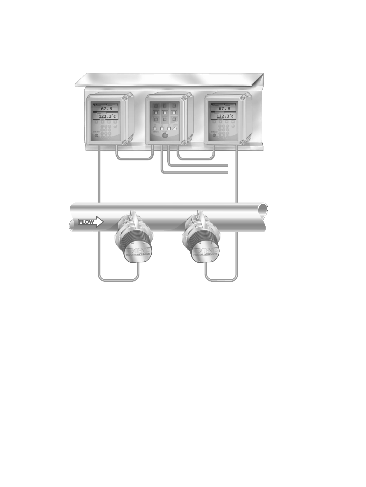
Figure 1.1 Complete Digital Black Liquor Divert Control System DD-23
Page 7

2 The Divert Control System DD-23
2.1 Overview
The Divert control system DD-23 includes:
− A Divert Control Unit
− Two isolation valves SDI for the refractometers above to allow removal of the re-
fractometers from a pipe with full low and pressure. The isolation valve includes
a prism wash nozzle and two check valves (one for prism wash, one for stufing
box lush).
− A roofed mounting plate to mount the two Indicating transmitters and the Divert
Control Unit together.
− Wiring to connect the Indicating transmitters with the Divert Control Unit.
− Two steam valves with steam traps for prism wash (pneumatic + solenoid valves).
− Two hand valves (one for prism wash, one for stufing box lush).
− A remote operator panel facility, accessible with a web browser over Ethernet
BLRBAC (The Black Liquor Recovery Boiler Advisory Committee) recommends a
spare refractometer sensor to be maintained in stock on-site.
3
2.2 Divert Control Unit
The Divert Control Unit is contained in an enclosure with the same dimensions as the
refractometer transmitter enclosure. The control unit includes:
− An operator with system state indicators and pushbuttons
− Relay outputs for connecting to the control system
− Contact inputs for external control
− Ethernet interface for remote operator panel
2.3 Operator panel
The operator panel has a clear layout and the operator can see all information at one
glance. The divert decision is controlled from the operator panel which provides doubled security, since information is shown both as LED indication in the Divert control
unit and as a diagnostic messages in the Indicating transmitters. The same information is also available through the remote operator panel.
Page 8
4
Red indicator
lights (alarms)
Yellow indicator
lights (warnings)
Green indicator
lights (all well)
White pushbuttons
Red push-button
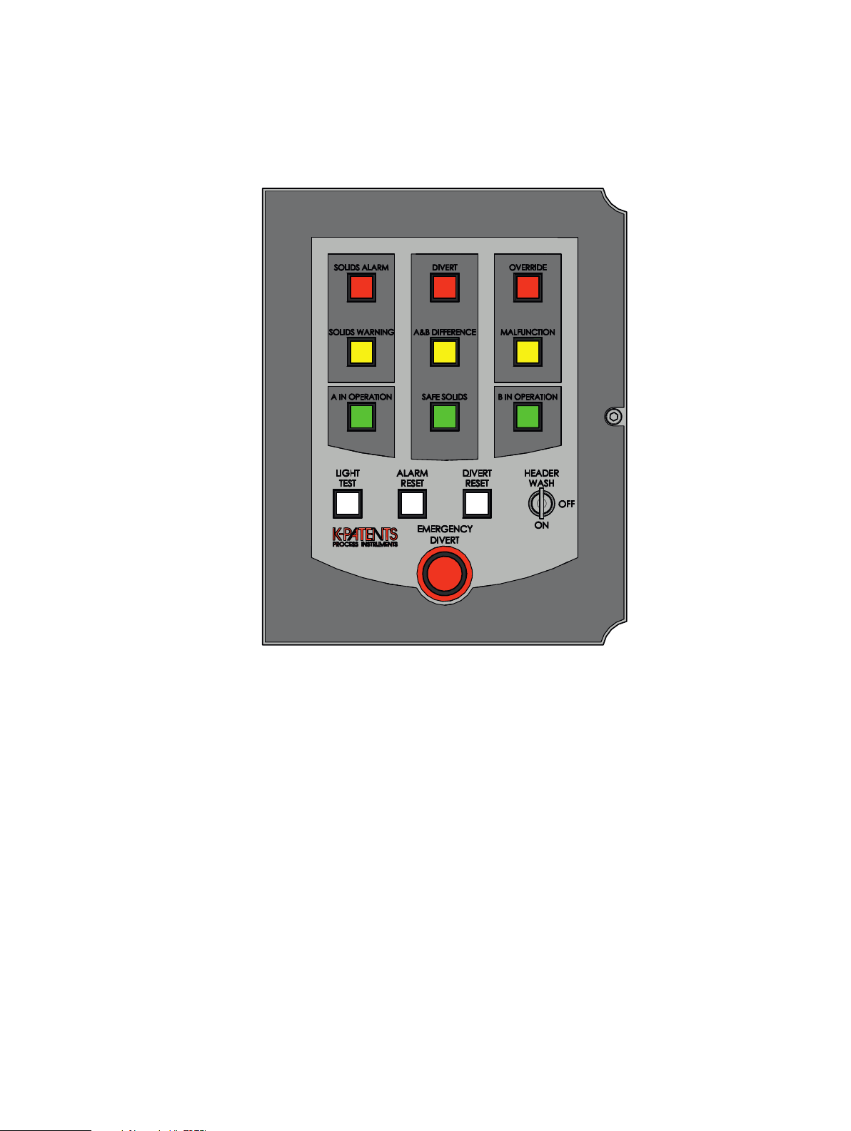
2.3.1 Overview
Figure 2.1 DD-23 operator panel
The three top rows on the operator panel consist of indicator lights. The green A IN
OPERATION and B IN OPERATION lights are also push buttons used to include the refrac-
tometers in the Divert system. Below the lights there are push buttons and the HEADER
WASH key key used to operate the system.
The indicator lights on the operator panel are arranged like trafic lights: top row is
red for alarm, middle row is yellow for warning and bottom row is green for "system
ok". When the system is running normally, only the row of green lights should be lit.
The white LIGHT TEST button is used to check that all the LEDs behind the indicator
lights are working. It also veriies the data processing system in the control unit. The
other two white push buttons, ALARM RESET and DIVERT RESET can be used to reset
the system back to normal after all problems have been ixed. The HEADER WASH key
enables the use of ring header washing with water, when set to ON.
The big red EMERGENCY DIVERT push button is used to manually initiate divert in an
emergency situation. An external push button can also be connected to a switch input
in the control unit as External Emergency divert button, see Section 2.3.8.
Page 9

2.3.2 Green indicator lights: System ok
Each refractometer has a green operating light – A IN OPERATION and B IN OPERATION –
to let the operator know when he can rely on the refractometer measurement. A refractometer will only inluence the divert decision and activate warnings and alarms
when it is in divert operation, i.e. when its green operating light is lit.
When DIVERT is effective, the system may be reset to normal operation only when
SAFE SOLIDS is lit.
2.3.3 Yellow indicator lights: Warnings
The SOLIDS WARNING light indicates a black liquor concentration of below warning
limit (by default at 60%). This warning can be activated by either refractometer.
The A&B DIFFERENCE light is lit when the refractometer readings differ by at least 2%.
This warning will only be initiated if both refractometers are operating.
If the yellow MALFUNCTION light is switched on, some part of the system – a refractometer, an indicating transmitter or the control unit – is malfunctioning. A list over
malfunctions and critical malfunctions is given in Section 6.2. If a critical malfunction
occurs in a sensor or transmitter, the malfunctioning refractometer will be automatically removed from divert operation (its operating light will also be switched off).
Check the reason for the malfunction and correct the problem (see Section 6.4) before returning the refractometer back to divert operation.
5
2.3.4 Red indicator lights: Alarms
The black liquor SOLIDS ALARM is lit when the concentration reading goes below alarm
limit (by default below 58%). This alarm can be activated by either refractometer
depending on the operation rule setting.
The DIVERT light will be switched on when the SOLIDS ALARM is activated. The DIVERT
light indicates divert status of the divert relay. The relay is inactive in the divert position, because then a power failure will give a divert decision signal to the system.
The OVERRIDE light is lit to indicate that no automatic divert will happen as long as
the system is in the header wash state (see Section 2.3.6).
2.3.5 White pushbuons: Tesng and reseng
The LIGHT TEST button switches all 12 lights on. The ALARM RESET button resets the
alarm lights.
Page 10

6
2.3.6 Header wash key: Enabling ring header wash
The header wash key function is a 3-level procedure which can be used when ring
header washing with water is needed. When the HEADER WASH key is switched to ON
position and information from black liquor guns switch inputs connected in series tell
that guns are out from recovery boiler, then a ring header wash can be done without
activating Divert.
Pushing the EMERGENCY DIVERT button will always initiate divert regardless of the
header wash functionality.
2.3.7 Emergency divert buon: Manual divert
The EMERGENCY DIVERT push-button is used to manually initiate divert in an emergency situation.
2.3.8 External emergency divert buon
An external (remote) push button can also be connected to an input inside the Control
unit, see Figure 3.3.
External emergency divert button must be normally closed (NC). Opening the circuit
will initiate divert.
2.4 Prism wash
The wash parameters for the sensors are set through each transmitter (Section 2.4).
The transmitters contain a relay for prism wash. To follow the BLRBAC recommendation not to wash both prisms at the same time, the Divert Control Unit implements an
interlock which prevents the instrument from washing both sensors simultaneously.
2.5 Indicang transmiers
Mechanically the Indicating transmitters shipped with a DD-23 are the same than
PR-23 Indicating transmitter DTR. The transmitter will only allow single sensor connection and a special DD-23 transmitter software is used for the Divert system. When
Divert software is 2.01 or newer, Indicating transmitter software version has to be
4.12 or newer.
For more information on the basic functions of an indicating transmitter, please see
the PR-23 manual, chapters 3 and 10.
Page 11
3 Mounng
For mounting of the process refractometers and the isolation valves, consult the separate process refractometer PR-23 instruction manual.
7
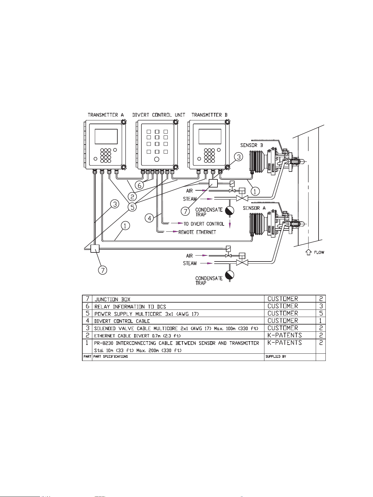
Figure 3.1 Mounng the Divert control system
3.1 Mounng prism wash
K-Patents recommends to use a steam trap instead of a preconditioning valve to remove condensate from the steam line.
Page 12
8
3.2 Wiring
For wiring for complete system, see Figure 3.2 which shows the connections to the
Indicating transmitters and to steam washing. Figure 3.3 has information of all connections to the Divert control unit.
Figure 3.2 Transmier wiring cables and connecons
3.2.1 Relays
Relay 1 NORMAL/DIVERT information
Relay 2 NORMAL/DIVERT information
Relay 3 SOLIDS WARNING: when one of the refractometers goes lower than the
solids warning limit, typically 60% or higher. See Section 5.6.1.
Relay 4 SOLIDS ALARM: when one of the refractometers goes lower than the solids
alarm limit, typically 58% or higher. See Section 5.6.2.
Relay 5 Refractometer signal difference warning: when the refractometerreadings
have more than 2% difference in concentration. See Section 5.5.
Relay 6 Horn relay: connection to the audible alarm. See Section 7.5.
Relay 7 Header wash key information. See Section 3.3.3.
Relay 8 Refractometer A malfunction information. See Sections 6.2 and 7.4.
Relay 9 Refractometer B malfunction information. See Sections 6.2 and 7.4.
Relay 10 Information on if refractometer A is active in the Divert Control System or
dropped off.
Relay 11 Information on if refractomter B is active in the Divert Control System or
dropped off.
Page 13
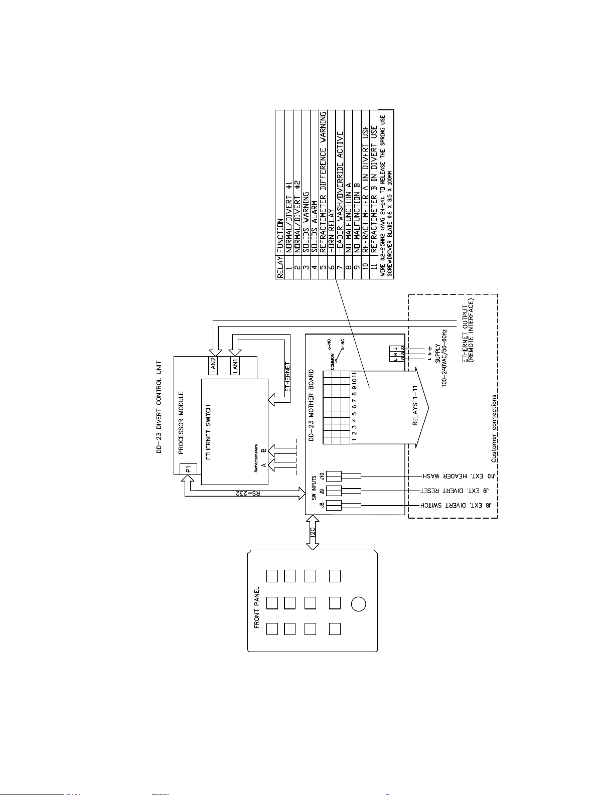
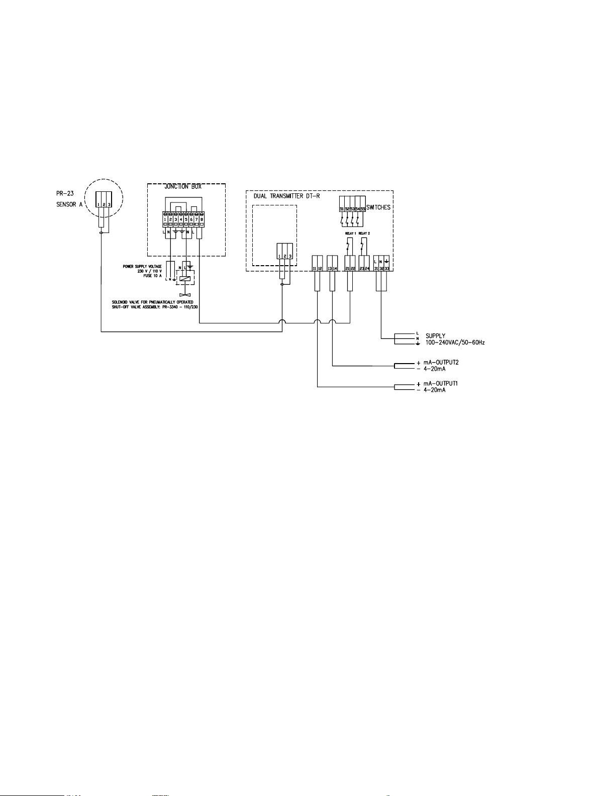
9
Figure 3.3 Divert control unit internal wiring
Page 14

10
3.3 Switch inputs
3.3.1 External Divert switch/push buon - input J8
An external divert switch can be connected to the DD-23 Divert Control Unit, input J8.
If the external divert switch is not used, a jumper has to be connected across J8. The
unit is delivered with this jumper connected.
3.3.2 External divert reset buon - input J9
If you want to use external Divert reset button, it can be connected max. 200 m (600 ft)
from the DD-23 Divert control unit. Use normal instrument cable 2x0.5 (AWG 20) and
connect cable to DD-23 motherboard input J9.
You must make sure both refractometers A and B are working OK before starting to
use the remote divert button (the remote interface can be used to check on the refractometers, see Chapter 8).
The external reset button connection is normally open (NO).
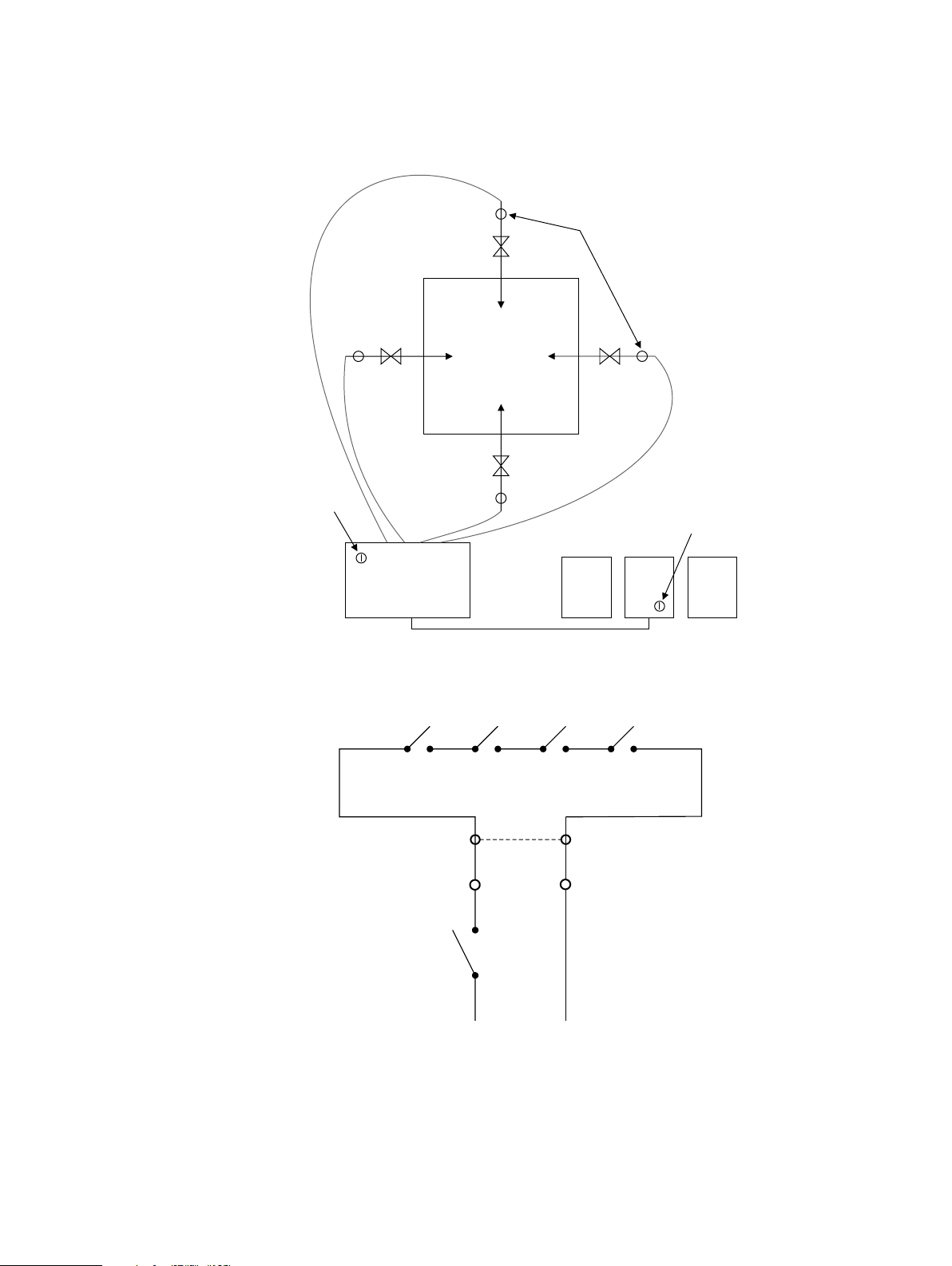
3.3.3 Header wash key - input J10
Black liquor is injected to the recovery boiler through liquor guns. Occassionally the
header ring needs washing and during that procedure the divert system has to be
by-passed and the liquor guns have to be removed from the furnace. The Digital Divert
Control System DD-23 allows for a safe override of divert logic during header ring
wash.
The override is mounted by connecting the gun micro switches in series to the Header
wash/override key switch input J10, see Figure 3.5.
The Header wash key may be used without the external switch information if a jumper
(dotted line in Figure 3.5) is placed to swith input J10. If the input is left open, the key
does not have any effect.
Page 15
11
DD-23
Operator panel
OVERRIDE
HEADER WASH
HEADER
WASH
KEY
MICROSWITCH
on each liquor gun or
on liquor gun door
Recovery
boiler
Guns out microswitches
HEADER
WASH
KEY
SWITCH INPUT
J10
Figure 3.4 Header wash key funconality
Figure 3.5 Header wash key connecons
Page 16

12
Ethernet output
3.4 Remote ethernet connecon
The Ethernet connection for the remote interface and data logging purposes is located
inside the Divert control unit on the right side of the processor unit. It is marked
Ethernet output.
Figure 3.6 Ethernet connecon
Page 17

4 Startup
4.1 Divert system pre-startup checklist
1. SDI Isolation valves mounted correctly
a. Vertical pipe; MTG453
b. Horizontal pipe; MTG471
2. DD-23 control unit installed; DIM243, Figure 9.1 on page 37
3. Pressure reducing valve, solenoid valve, steam trap installed and connected to the
prism wash nozzle on each sensor
a. Steam pipes for black liquor; MTG470
b. Nozzle; MTG482
4. 9–15 bar (130–220 psi) steam connected to the solenoid valve on each sensor
5. Instrumentation air 4–6 bar (60–90 psi) connect to the solenoid valve on each
sensor
13
6. Power supply (230/110Vac/24Vdc) connected; SYS358/Figure 3.1 on page 7, and
WRG366, Figure 3.1 on page 7
a. Transmitter A
b. Transmitter B
c. Divert control unit
d. Solenoid valve A
e. Solenoid valve B
7. Cables connected; SYS358/Figure 3.1 on page 7, WRG366, Figure 3.1 on page 7
a. Transmitter A to sensor A
b. Transmitter B to sensor B
c. Transmitter A to solenoid valve A
d. Transmitter B to solenoid valve B
e. Relay information from the Divert control unit to your control system or the
Divert valve
f. Transmitter A mA output to your control system
g. Transmitter B mA output to your control system
h. Ethernet to your control system (optional)
Page 18

14
4.2 Divert control unit DD-23 startup
Forthe refractometer startup, consult Chapter 5 in the separate Process refractometer
PR-23 manual.
1. Check the wiring and supply voltage.
Before the power is switched on, the divert output relay ’normal operation’ is in
divert position.
2. Connect the mains power to start the system.
There are no power switches in the instruments. They are always On when the
mains power is connected.
3. While the Control unit is powering up, the DIVERT and SOLIDS ALARM lights are both
blinking. When the unit is fully functional, it is in the divert mode: the DIVERT light
is on and the SOLIDS ALARM light is blinking.
4. Press the LIGHT TEST button on the Divert control unit. All 12 lights should switch
on.
5. Reset the solids alarm by pressing the ALARM RESET button.
The indicator stops blinking and should stay on.
6. Each indicating transmitter should now state refractometer letter, either a or b, in
the upper left corner of the transmitter display. If there’s a question mark instead
of a letter on either of the transmitters, see Chapter 6.
If the process pipe is full, the message for each refractometer should be NORMAL
OPERATION; if process pipe is still empty, message will be NO SAMPLE.
Now activate refractometer A into the Divert by pushing the button A IN OPERATION
on the Divert control unit panel. The button lights up and on the transmitter display the refractometer letter changes to capital A. Then activate refractometer B
similarly by pushing the button B IN OPERATION.
If the green IN OPERATION light blinks, the refractometer in question is perform-
ing wash. The refractometer will automatically come into operation after it has
inished washing.
7. Now the Divert control system DD-23 is set for normal monitoring operation.
8. When black liquor is in the line, check that the prism wash is working for each
refractometer. First press soft key MENU on the transmitter keyboard, then choose
3 SYSTEM STATUS to get to the system status display. Now press soft key WASH to
initiate manual wash; follow the optical image and check that it changes during
the steam wash. If wash was successful, wait until message is NORMAL OPERATION
and then proceed with startup. If wash doesn’t seem to work, see Chapter 6.
9. If the three green lights on the third row are all on and all conditions for safe boiler
operation are satisied, turn off diversion by pressing the DIVERT RESET button. All
warning lights are now turned off and only the 3 green lights are on.
Page 19

5 Configuraon
CALIBRATION
LOCK
CALIBRATION
LOCK
The K-Patents Divert control system is shipped fully calibrated by the manufacturer.
This chapter contains instructions on how to make ine adjustments of the system.
5.1 Calibraon lock
Parameter changes are possible only when the calibration lock is open. The calibration lock can be closed by a switch inside the control unit cover (see Figure 5.1). When
the lock is open, a red led is illuminated next to the lock switch. For safety reasons,
keep the calibration lock open only during parameter changes, done through the web
interface (see Chapter 8).
15
Figure 5.1 Locaon of the calibraon lock
Page 20

16
5.2 Divert decision rules
Two refractometers in operation:
BLRBAC states the following: For the solids measurements, two refractometers in series must be used. When both refractometers are in service, the requirement for an automatic black liquor diversion can be satisied by either of the following options:
1. If either refractometer reads dissolved solids content 58% (default) or below,
an automatic black liquor diversion must take place.
2. When both refractometers read dissolved solids content 58% (default) or be-
low, an automatic black liquor diversion must take place.
Either option is satisfactory.
The rules are listed in decreasing order of security. Only rule 1 satisies the high safety
requirements set by BLRBAC, August, 1982. On the other hand, the probability of false
trips decreases with decreasing safety. It means that if false trips are too frequent, the
rule 2 may be preferred at the cost of safety. The rule 2 has later been accepted by
BLRBAC.
The divert decision rule is selected by the rule switch inside the divert control unit
cover (Figure 5.1). The state of the switch is indicated by a yellow indicator LED for
rule #2 and a green one for rule #1.
Rule switch Rule
1-of-2 Rule #1
2-of-2 Rule #2
Table 5.1 Divert decision rule selecon.
The logical description of the safety decision logics is given Tables 5.3 and 5.2 below.
A
under 58% over 58%
B
B
under 58% divert divert
over 58% divert safe
Table 5.2 Two instruments in operaon, rule 1-of-2
A
under 58% over 58%
under 58% divert unsafe
over 58% unsafe safe
Table 5.3 Two instruments in operaon, rule 2-of-2
Page 21

Only one refractometer in operation:
When only one instrument is in operation the divert action takes place if this instrument reads 58 % or below. The rule selection has no inluence on the divert decision
in this case.
A or B
under 58% unsafe
over 58% safe
Table 5.4 Operaon logic when only one instrument operang
No refractometer in operation:
If both instruments are out of operation (due to malfunction or maintenance), then
according to BLRBAC divert action must take place.
Emergency divert
In all cases the system may be set to DIVERT by pressing the EMERGENCY DIVERT button
(or an external emergency divert button, see Section 2.3.8).
17
5.3 Refractometer concentraon measurement
For refractometer calibration consult also Chapter 6 in the separate Process refractometer PR-23 Instruction manual.
The CONC% displays of the two indicating transmitters have to show the same value
within 0.5 %. If there is a difference, this can be eliminated by adjusting the bias for
one of the refractomers; comparison with sample determination can decide which
one should be corrected.
In the PR-23 refractometer system, bias is the parameter F00, the third parameter in
the ield adjustment parameter list. To change it, irst press the MENU soft key, then
5 CALIBRATION, then 1 CHEMICAL & FIELD PARAMETERSand then 2 FIELD CALIBRATION PARAMETERS. Choose 3 F00 (BIAS) to change the bias (see Section 6.2.5 in the PR-23 manual).
If the Indicating transmitter A displays 68.2% and B displays 68.8%, the difference can
be eliminated by lowering B by 0.6%. This is done by setting the ield calibration
parameter F00 to -0.6 in Indicating transmitter B.
Due to its digital measurement principle, the readings of the K-Patents Process refractometer do not drift by time. Frequent recalibrations based on ofline moisture analysis must be avoided, as they will introduce random luctuations to the refractometer
readings.
Page 22

18
5.4 Refractometer acvaon for divert control
When a refractometeris activated for Divert control, the upper left corner of the transmitter display shows alternatively A, a, B, b or ?. If the corner is blank, the instrument
is not suitable for divert operation.
Transmier A, in
Divert operaon
Figure 5.2 Indicang transmiers (STR) acvated to Divert control
The decision to display A (a) or alternatively B (b) depends on the IP address settings
in the transmitter. The IP address of instrument A is 172.16.23.2 and that of instrument B is 172.16.23.3. These addresses have been set in the factory and should not be
changed. (See Chapter 8 for information on system IP address and connecting to the
DD-23 system.)
If a question mark appears on the transmitter display, the reason is usually that the
Ethernet cable between the transmitter and the Control unit is not properly connected
or the Divertcontrol unit is not powered on. Reconnect (or replace cable, if necessary)
to ix.
The refractometer program version has to be 3.00 or higher to have divert system
functionality. Divert version 2.01 or higher requires DTR software version 4.12 or
higher. Also, the refractometer has to have the correct software parameters to be used
in a divert control system. In order to convert a stand-alone refractometer into one
used on the Divert control system, please contact K-Patents. The easiest way to check
if a refractometer is conigured for DD-23 use is to look at the main display. If the
?/a/A/b/B letter is present (see Figure 5.2), the instrument may be used in the Divert
control system.
If a DD-23 activated transmitter is used in another type of application, the divert function has to be deactivated by K-Patents.
Transmier B, not
in Divert operaon
Ethernet connecon failure
5.5 Signal difference alarm
According to BLRBAC, if a difference of 2% in solids (absolute value) or greater exists
between refractometer readings, an alarm shall be activated.
The alarm limit of 2% is the maximum difference. The limit can be changed into a
smaller number through the remote interface, see Chapter 8.
Page 23

5.6 Low alarms
5.6.1 Solids warning
If the concentration reading of either refractometer falls below this limit (60% by default), the warning is activated. The limit can be changed through the remoteinterface,
see Section 8.2.5.
Minimum low warning level is 60% according to BLRBAC.
5.6.2 Solids alarm
If the concentration reading of either refractometer falls below this limit (58% by default), the alarm is activated. The limit can be changed through the remote interface,
see Chapter 8.
Minimum low alarm level is 58% according to BLRBAC.
5.7 Refractometer malfuncon alarm
The built-in intelligent diagnostics of a K-Patents Process refractometer provide a
tight control of the operation. A full test cycle is completed with an interval of less than
one second. For details consult the Process refractometer PR-23 instruction manual.
19
Not all malfunctions cause the instrument to be removed from the Divert control system. However, all malfunction alarms need to be checked, see Section 6.2 for more
information.
5.8 Prism wash
Even though the sensors are equipped with a steam wash facility, it is not necessarily
needed. For K-Patents Process Refractometer, the need of prism wash is reduced and
even in some cases eliminated.
However, an automatic regular prism wash provides an eficient check that the refractometer reacts. A steam wash of 3 seconds every half hour should be suficient.
Only one instrument is washing at a time, and during the wash the system acts in the
single-instrument mode.
To change wash times or relay conigurations, consult the PR-23 process refractometer system manual, sections 6.1.3. Coniguring relays and 6.3.1. Setting prism wash
parameters.
Page 24

20
The recommended wash pressures and times are given in the table below..
Wash parameters for Safe-Drive™ Isolaon valve nozzle SDI
Minimum above
process pressure
Steam (SN) 5 bar (70 psi) 8 bar (115 psi) 3–5 s 20–30 s 20–30 min
Maximum above
process pressure
Wash
me
Reco-
very
Do not exceed the recommended wash times, because some process media may burn
to the prism surface if steamed for longer time. In case of coating, shorten the wash
interval.
It should be noted that if wash check is enabled on the instrument it can cause the
instrument to be taken out of divert use if during the set wash tolerance time no wash
cycles have been noted as successful. This can cause a divert if both instruments fail
wash checks in sequence.
Interval
Page 25

6 Regular maintenance and troubleshoong
As the Divert control system is a pure digital system, no special maintenance is needed.
The LIGHT TEST button on the operator panel (Figure 2.1) sends a signal to the microprocessor, and the microprocessor switches all 12 LED lights on as long as the button
is pressed. This way not only the lights but also the processing system is checked.
To assist the identiication of a faulty component, the information low is given in Section 6.1. Also the logic diagrams of Chapter 7 may be of help.
6.1 Informaon flow
The divert control unit is connected to the refractometers through an Ethernet connection. The Control system asks for the measurement data from the instruments
several times each second. Based on the data received the divert operation decisions
are made.
Each refractometer performs its measurement functions independently. The instruments also have their own internal diagnostics, which are used in the divert decision
logic, as well (see Section 6.2).
21
As the Divert Control System requests information several times a second, all communication problems are found immediately. In case one of the refractometers does not
respond to the control unit, the non-responding instrument is dropped from operation and the malfunction alarm is set.
An important information when troubleshooting communication problems is the letter on the upper left corner of each refractometer (see Figure 5.2). If the instrument
has not received any data requests from the DivertControl Unit during the last second,
the letter turns into a question mark (?). If the letter is a/A/b/B, then the communication link between the Divert control unit and the instrument is fully functional.
6.2 Malfuncons
If the Divert Control Unit cannot communicate with a refractometer, or if the internal diagnostics of a refractometer indicate a measurement problem, the Malfunction
indicator (see Figure 2.1) is illuminated and the corresponding relay 8 or 9 (see Figure 3.3) is activated.
The diagnostic message of the refractometer can be seen on the transmitter screen
(see Figure 5.1). Some of these messages, e.g. PRISM WASH, are only informative and
do not indicate a measurement problem. Table 6.1 below summarizes all diagnostic
messages and their effect on the Divert control system operation.
Page 26

22
If the malfunction is severe enough to make the measurement result unreliable,
the refractometer cannot be used in making the divert decision. In that case the
instrument is dropped from the Divert Control System, and cannot be taken on-line
manually until the problem is ixed.
For more information on possible causes of each error, see the PR-23 instruction manual, Chapter 8.
Message Instrument will be
dropped from the
Divert Control System
EXTERNAL HOLD
EXTERNAL WASH STOP
HIGH SENSOR HUMIDITY
HIGH SENSOR TEMP
HIGH TRANSMITTER TEMP
LOW IMAGE QUALITY X
LOW TEMP WASH STOP
LOW TRANSMITTER VOLT
NO OPTICAL IMAGE X
NO SAMPLE X
NO SAMPLE/WASH STOP
NO SENSOR X
NO SENSOR SIGNAL X
NORMAL OPERATION
OUTSIDE LIGHT ERROR X
OUTSIDE LIGHT TO PRISM X
PRECONDITIONING
PRISM COATED X
PRISM WASH
PWASHFAIL X
PWASHWARN
RECOVERING
SHORT-CIRCUIT X
STARTING UP... X
TEMP MEASUREMENT FAULT X
Table 6.1 Diagnosc messages and their effect on Divert operaon
Page 27

6.3 Diagnosc tools
In order to make troubleshooting easier, there are several built-in diagnostic tools.
An event log is built in the system. A short log showing last 6 events can be accessed
from the transmitter main display by pressing the soft key DD23. A more complete
event log can be found in the web-based remote interface (see Section 8.2.4).
Figure 6.1 Transmier log page for instrument A
The remote interface also provides a diagnostic page which gives full information on
the system state (concentrations, relay state, switch state, indicator state), see Section 8.2.3.
23
6.4 Troubleshoong
6.4.1 A queson mark (?) on the refractometer display
Cause: The refractometer does not receive information request packets from the Divert Control Unit. This may be caused by a faulty cable, faulty parameters, or equipment malfunction either in the refractometer or in the Divert Control Unit.
Action: If the instrument has never been functional, or if it is possible someone has
changed the instrument parameters, there may be a coniguration problem with the
IP addresses. The IP address in the refractometer should be set as givenin Section 5.4.
If possible, cross-check the addresses from the diagnostic web page.
A physicalproblem can be ruled out by looking at a small LED close to the transmitter’s
Ethernet connector. If the LED is green, the cable is ok. One way to isolate the problem
is to swap the cables between the refractometers. A standard Ethernet cable can be
used as a troubleshooting aid (either straight-through or cross-over).
6.4.2 A refractometer refuses to come on-line
Cause: Either there is no communication to the refractometer or there is a malfunction on the refractometer. It is also possible the transmitter is not conigured for Divert
use.
Page 28

24
Action: Check that there is a/A/b/B on the refractometer display. If there is a question
mark (?) instead, see above.
Check that there is a soft key DD23 on the refractometer main display (see Figure 6.2
below). If the soft key is not present in the main display, the instrument is not conigured for Divert use. If this is the case, please contact K-Patents.
In other cases, check the diagnostic message on the refractometer screen (see Section 6.2).
Figure 6.2 Transmier main display, instrument in Divert use
6.4.3 No lights come up in the Divert Control Unit
Cause: There is no power on the instrument or there is a hardware fault.
Action: Check that the instrument receives power. In normal operation several relays
have their associated LEDs lit. If there are any LEDs lit in the Divert Control Unit, the
unit receives power.
6.4.4 All lights are blinking
Cause: There is an unrecoverable hardware fault in the Divert Control Unit.
Action: Please contact K-Patents.
Page 29

7 Divert control logics
no
no no
no
yes
UNSAFE SOLIDS
SAFE SOLIDS
NO INSTRU-
MENTS!
Rule 2-of-2
2 instruments
available?
1 instrument
available?
Both ≥ 58%?
Either ≥ 58%?
CONC ≥58%?
yes
yesyes
yes
no
Rule 1-of-2?
yes
no
DIVERT
A logical description of the system is provided to complement the operational description given in the previous chapters.
7.1 Safety decision logic
The core of the Divert control system is the safety decision logic, which makes the
ultimate decision whether the black liquor can be safely fed to the burner or not.
The logic is described in the low diagram in Figure 7.1. The factors affecting the decision are the number of instruments in operation (none, one or two) and their measurement results. Also the selected divert rule is taken into account when two instruments are in operation. For a description of different rules, see Section 5.2.
As a result of this logic, the system is either in SAFE SOLIDS or UNSAFE SOLIDS state.
When the system is in the SAFE SOLIDS state, the SAFE SOLIDS light is illuminated.
25
"One instrument available" may mean that only one instrument is in operation or that
both instruments are in operation, but one of them is washing when queried.
Figure 7.1 Safe solids decision logic
Page 30

26
NO DIVERT
DIVERT
HEADER WASH
active?
Divert from
safe solids logic?
EMERGENCY
DIVERT
pressed?
DIVERT RESET
pressed?
yes
no
yes
no
yes
no
no
yes
7.2 Divert decision logic
After the system has evaluated the solid contents to be either safe or unsafe (see Section 7.1), it decides whether the the system should be in the DIVERT state. This decision is made according to the low diagram in Figure 7.2.
The defaultstate of the system is the DIVERT state. It can be changed to the NO DIVERT
state only by manually pressing the DIVERT RESET push-button when the solid content
is suficient (SAFE SOLIDS). If the solid content drops to UNSAFE, the system drops
into the DIVERT state.
The only exception to this is when the HEADER WASH is active. In that case the solid
content checking is skipped. The system may then be switched between the DIVERT
and NO DIVERT states by using the EMERGENCY DIVERT and DIVERT RESET push buttons
in the operator panel (or the equivalent external emergency divert and divert reset
buttons).
The system will drop to the DIVERT state in all cases when the EMERGENCY DIVERT
button (or its external counterpart) is pressed.
Figure 7.2 The divert decision logics
Page 31

7.3 In operaon logic
IN OPERATION
button pressed
yes
yes
yes
yes
no
no
wash done
no
no
no
Only
instrument?
Washing?
IN OPER.
pressed?
Critical
malfunction?
WAIT
(LIGHT BLINKING)
IN OPERATION
(LIGHT ON, RELAYS
10, 11 ACTIVE)
Critical
malfunction?
NOT IN OPERATION
(LIGHT OFF)
yes
Whether an instrument is in operation depends on the operator’s commands and the instrument’s diagnostics. The decision
is carried out as outlined in Figure 7.3
An instrument can be in one of
three different states: IN OPERATION, NOT IN OPERATION, and
WAIT. When the instrument is IN
OPERATION, it is used in deciding whether the solid content is
in the safe level (see Section 7.1).
When the instrument is NOT IN
OPERATION or WAIT states, it is
not used.
27
The WAIT state occurs when the
operator has requested the instrument to come into operation
by pressing the button, but the
instrument is in the wash cycle
and will come into operation after the wash cycle is completed.
The actual state can be seen from
the IN OPERATION light. If the light
is on, the instrument is IN OPERATION. If the light is off, the instrument is NOT IN OPERATION,
and if the light is blinking it is in
the WAIT state.
The default state of an instrument is to be NOT IN OPERATION. It can be taken into operation by pressing the IN OP-
ERATION button unless there is
a critical malfunction (see Section 6.2).
Figure 7.3 Operaon logic
An instrument automatically drops
into NOT IN OPERATION if there
is a critical malfunction. It may also be dropped by the IN OPERATION button unless it
is the only instrument used.
Page 32

28
Timeout from
instrument?
Malfunction in
instrument?
no
yes
yes
yes
no
no
Critical malfunc-
tion in instr.?
NO
MALFUNCTION
Remove instr.
from Divert use
MALFUNCTION
7.4 Malfuncon logic
The MALFUNCTION light is illuminated when the internal diagnostics of either of the two instruments indicates a malfunction or
there is a communication timeout
to either of the instruments (Figure 7.4).
It should be noted that not all malfunctions are critical malfunctions
which drop the instrument from
operation (see Section 7.3). For a
complete list of possible malfunctions, see Section 6.2.
The MALFUNCTION light relects the
decision taken by this logic. However, as the MALFUNCTION light is
one of the resettable alarms, it
may be blinking even when the
malfunction itself is cleared if the
ALARM RESET button has not been
pressed (see Section 7.5).
Figure 7.4 Malfuncon logic (repeated for each sensor)
Page 33

UNACKNOWLEDGED
ALARM
(Blinking, Relay 6 active)
ALARM
(Light on, Relay 6 inactive)
Alarm source active?
ALARM RESET
pressed?
Alarm source active?
yes
no
no
no
yes
yes
NO ALARM
(Light off, Relay 6 inactive)
29
7.5 Reseable alarm logic
In order to identify new alarms, there
is a resettable alarm logic in the Divert control unit. There are four possible alarm sources: SOLIDS ALARM,
SOLIDS WARNING, A&B DIFFERENCE,
and MALFUNCTION. All of these follow the same alarm reset rules (see
Figure 7.5).
When a new (unacknowledged) alarm
activates,the corresponding light starts
blinking in the operator panel, and relay 6 is activated. When the ALARM RE-
SET button is pressed, relay 6 is inacti-
vated.
The state of the alarm indicator in the
operator panel depends on whether
the cause for the alarm is still present.
If the cause has cleared (e.g. solids
content has risen above the warning limit), the light goes off when
the ALARM RESET is pressed. If the
cause has not cleared, the light will be
steadily illuminated.
A non-illuminated light means there
is no alarm. A steadily illuminated
alarm light means there is a problem
which persists but the problem has
been acknowledged by pressing the
ALARM RESET. A blinking light means
the problem has not been acknowledged, but gives no information whether
the problem is still there or not.
Figure 7.5 The reseable alarm logic
Page 34

30
no REFRACTO-
METER
DIFFERENCE
|A-B| > 2%?
2 instruments
available?
yes
no
no
yes
REFRACTO-
METER
DIFFERENCE
7.6 Refractometer difference logic
If there are two refractometers in operation (taken into operation, not washing), the
Control unit monitors the difference in reading between the two instruments (igure 7.6). If the difference is more than 2%, a refractometer difference warning is given
with the corresponding front panel indicator and relay.
The divert decision logic (section 7.2) is not affected by the refractometer difference,
but a signiicant difference between the two instruments indicates one of the instruments is not measuring reliably. In this case the instruments and wash systems have
to be checked immediately. Ignoring to do this may result in an erroneous divert decision.
Figure 7.6 Refractometer difference logic
Page 35

7.7 Wash arbitraon logic
no
WAIT
WASH
IDLE
The other
instrument
washing?
yes
wash interval
elapsed
wash done
the other instrument
done washing
The Divert Control Unit takes care that if there are two instruments in operation, they
won’twash at the same time (as that would trip the system). This is done by the simple
logic described in Figure 7.7
Each instrument control their own wash cycle. Before the start washing, they request
a wash permission from the Divert Control Unit. If the other instrument is already
washing, the unit does not grant this permission until the wash cycle is completed.
31
Figure 7.7 Wash arbitraon logic
Page 36

32
Wash check?
Wash tolerance
time > 0?
no
yes
yes
off
yes
on
no
Prism wash
succesful?
Drop from
Divert use
Malfunction
Succesful wash
within tolerance
time?
Prism wash failure
Prism wash
warning
no
Normal operation
One wash cycle
7.8 Wash check logic
By default the wash tolerance time is 0.
Figure 7.8 Wash check logic
Page 37

8 Remote control interface
The remote interface is based on a web server inside the Divert Control Unit. It consists of several web pages, easily accessible through the links on the navigation bar in
the left (see Figure 8.1).
The remote interface is optimized for the Firefox browser, version 2.0 or newer, although it may work with other browsers. Firefox is free and exists for Windows, Mac
OS X and Linux, it can be downloaded through http://www.mozilla.com/.
8.1 Divert Control Unit IP address
The Divert Control Unit can be reached through two different IP addresses. In
non-networked applications (only a DD-23 and a single computer) the IP address is
169.254.23.23. This IP address is factory set and cannot be changed. If the Divert Control Unit is to be connected to a network, the network settings can be changed through
the parameter page of the remote interface (see Section 8.2.5).
8.2 The remote interface
33
8.2.1 Main page
The remote indicator main page gives a quick overview over system status.
Figure 8.1 DD-23 Remote control, main page
Page 38

34
8.2.2 Instrument pages
The pages for instrument A and instrument B are normal transmitter homepages. See
the PR-23 instruction manual, Chapter 12, for more information.
By default, the instrument pages open in a new tab in your browser; the DD-23 page
you started from will stay open in the original tab.
8.2.3 Diagnoscs page
The diagnostics page gives a full account on instrument settings and the instrument’s
status at the moment, including information about relays, switches, pushbuttons, etc.
Figure 8.2 Remote diagnoscs page
Page 39

8.2.4 Log page
The log page gives a more extensive, printable log of events.
Figure 8.3 Remote log page
35
Page 40

36
8.2.5 Parameters page
The Divert Control Unit parameters can only be changed through the parameter page.
However, note that the calibration lock (see Section 5.1) has to be open (off) before
parameters can be changed. If calibration lock is on, parameter changes are not possible. The calibration lock status is given on top of the parameter page and if the lock
is on, i.e. changes are not permitted, the Submit button is missing.
Figure 8.4 Parameter page
8.3 Data logging
K-Patents provides free of chargea data logging software called K-Patents Toolkit (or
PR-11111). Divert logging functionality was introduced in Toolkit version 2.20. If you
have an earlier version of the Toolkit, please contact your K-Patents representative for
a version that is compatible with DD-23.
Page 41

9 DD-23 specificaons
9.1 Divert Control Unit specificaons
Model: DD-23
Enclosure: IP66 Nema 4X, dimensions 226 x 267 mm (8.91 x 10.5 in)
Supply: 86–240 V AC, 20 VA, 50-60 Hz
Ambient temperature: max 45C(113F)
Accessory: Roofed stainless steel mounting plate for the Divert Control
Unit and 2 Indicating transmitters, Figure 9.1
Material: AISI 316, dimensions 916 x 488 mm x 250 mm
(36 x 19.2 x 10 in)
Relays 1-11: 3A, 250V NO/NC
37
Figure 9.1 Divert Control Unit mounng plate: Dimensions (mm/in)
Figure 9.2 Divert control unit and Indicang transmier closures: Dimensions (mm/in)
Page 42

38
7
1
4
2
3
5
6
9
8
9.2 Divert control unit spare parts
Figure 9.3 Divert Control Unit spare parts
No. Part name Spare part no.
1 DD-23 front panel PR-12100
2 Nikkai LB-15WK switch PR-12101
3 Nikkai SK-12AA key switch PR-12102
4 PR-12020 card PR-12020
5 Moxa switch EDS-205 PR-12103
6 Connector card PR-12010 PR-12010
7 Moxa US-7110-LX processor PR-12104
8 WRA24SX-U power supply PR-10810
9 Enclosure PR-7602
DD-23 motherboard–keyboard cable PR-12105
DD-23 motherboard–Moxa cable PR-12106
Page 43

10 Oponal Remote Divert Terminal DD-23-RT
The Remote Divert Terminal DD-23-RT is an optional extension to the normal DD-23
remote (web) interface. The system consists of a terminal with a touch screen for
navigating the remote interface menus and under the display buttons for the Divert
and Divert Reset operations.
10.1 Mounng instrucons
The DD-23-RT panel is compatible with VESA 100 wall mounts and swivel arms. It
can also be mounted in a rack or a table stand. An optional table stand is available
from K-Patents.
39
Figure 10.1 DD-23-RT display dimensions
Figure 10.2 DD-23-RT with K-Patents Table stand.
Page 44

40
Figure 10.3 Connecng DD-23-RT
Page 45

41
Figure 10.4 Wiring DD-23-RT
Page 46

42
Panel front
Power
0
1
10.2 Startup and use
Connect wires and cables according to Figure 10.4. In the Divert Control Unit the Remote Panel is connected to the Ethernet output, see Figure 3.6 on page 12. The Indicating transmitters (STRs) and the Divert Control Unit can stay powered on all the
time. The remote panel can also be connected to a factory network.
Switch on remote panel power. The power switch is located at the bottom of the
PR-23-RT panel.
Figure 10.5 Locang the power buon
The remote panel is a touch screen, tap the screen to operate. For remote interface
use, please see Chapter 8, “Remote control interface”.
10.3 Troubleshoong
Contact your nearest K-Patents representative, see http://www.kpatents.com/contacts.php,
or contact K-Patents, Inc, US phone (630) 955 1545, or the K-Patents headquarters,
phone +358 207 291 570.
Page 47

A Index
43
A
A IN OPERATION 4
ALARM RESET 4
A&B DIFFERENCE 5
alarm
see horn relay
logic 29
refractometer malfuncon 19
reset 4
signal difference 18
solids alarm 19
solids warning 19
B
B IN OPERATION 4
BLRBAC 3, 6, 16–19
buon
ALARM RESET 4–5, 14
DIVERT RESET 4, 14
EMERGENCY DIVERT 4, 6
external emergency divert 6
LIGHT TEST 4–5
C
calibraon lock 15, 36
coang
see prism coang
D
DD-23-RT 39
DIVERT 5
DIVERT RESET 4
Divert Control System 1
mounng 7
overview 3
parts 1
Divert Control Unit 3
IP address 33
mounng 37
spare parts 39
specificaons 39
wiring 9
diagnosc
message 21
tools 23
web page 34
disposal 1
divert decision logic 26
divert reset
external 10
divert rule
decision 16
switch 15
E
EMERGENCY DIVERT 4, 26
ethernet connecon 12
event log 23
saving 36
web page 35
external
divert reset buon 10
emergency divert buon 6, 10
H
HEADER WASH 4
header wash key 4, 6
mounng 10
horn relay 8
I
Indicang transmier 6
IP address 18
wiring 8
IP address
Divert Control Unit 33
Indicang transmier 18
indicator light 4
input
see switch input
instrument web page 34
J
J9, J10, J11
see switch input
K
key
see header wash key
L
LIGHT TEST 4
light
A IN OPERATION 4
A&B DIFFERENCE 5
B IN OPERATION 4
blinking DIVERT 14
blinking SOLIDS ALARM 14
blinking, all 24
DIVERT 5
green 5
MALFUNCTION 5
OVERRIDE 5
red 5
Page 48

44
SAFE SOLIDS 5
SOLIDS WARNING 5
yellow 5
logic
alarms 29
divert decision 26
in divert operaon 27
malfuncon 28
prism wash 31
refractometer difference 30
safe solids 25
safety decision 16, 25
M
MALFUNCTION 5
malfuncon 21
light 5
logic 28
message
NO SAMPLE 14
NORMAL OPERATION 14
messages 22
mounng
Divert Control System 7
Divert Control Unit 37
external Divert reset buon 10
external emergency divert 10
header wash key 10
prism wash 7
N
NO SAMPLE 14
NORMAL OPERATION 14
network sengs 33
O
OVERRIDE 5
one-of-two 16
operator panel 4
P
panel
see operator panel
parameters
Divert Control System 36
prism wash 19
web page 36
prism coang 20
prism wash 6, 19
arbitraon logic 31
mounng 7
steam pressure 20
mes 20
push buon 4
Q
queson mark 23
R
Remote Divert Terminal DD-23-RT 39
refractometer
bias 17
difference logic 30
malfuncon alarm 19
relay
wiring 10
remote
diagnoscs page 34
ethernet connecon 12
instrument page 34
interface 33
log page 35
parameters page 36
terminal DD-23-RT 39
reset
alarm 4
divert 4
ring header wash
see header wash key
rule
1-of-2 16
2-of-2 16
S
SAFE SOLIDS 5
SOLIDS ALARM 5
SOLIDS WARNING 5
safety decision logic 16, 25
sengs
network 33
signal difference alarm 18
solids alarm 19
solids warning 19
spare parts
Divert Control Unit 39
startup
Divert control unit 14
refractometer 14
steam trap 7
steam wash
see prism wash
switch
divert decision rule 16
1-of-2 16
2-of-2 16
switch input 6, 10
T
tesng
Page 49

45
Divert Control Unit 21
lights 21
transmier
see Indicang transmier
two-of-two 16
W
warning
see solids warning
warranty 1
wash
see prism wash
web pages 33
web server 33
wiring
Divert control unit 9
Indicang transmier 8
relay 10
Page 50

PROCESS INSTRUMENTS
K-Patents Oy
P.O. Box 77
fi-01511 Vantaa, Finland
tel. +358 207 291 570
fax +358 207 291 577
info@kpatents.com
K-Patents, Inc.
1804 Centre Point Circle, Suite 106
Naperville, IL 60653, USA
tel. (630) 955 1545
fax (630) 955 1585
info@kpatents-usa.com
K-Patents (Shanghai) Co., Ltd
17-05H, 17F, Times Square, No.500
Zhang Yang Road
Pudong District, Shanghai, China
tel. +86 21 5178 2775/5178 2787
fax +86 21 5178 2799
www.kpatents.com
 Loading...