

Page 1

WARNING
INSTRUCTION MANUAL
FOR DD-01
DIGITAL DIVERT CONTROL SYSTEM VERSION 4.1.
WITH MAIN PROGRAM 8.5 OR HIGHER
The process medium may be hot or otherwise hazardous. Precautions when removing the sensor from
the process line:
Make sure that the process line is not under pressure. Open a vent valve to the atmosphere. For a retractor/isolation valve the line pressure should be within specifications.
For a prism wash system, close a hand valve for the wash medium and disable the wash valve. Loosen the clamp or flange bolts cautiously, be prepared to tighten again. Be out of the way of any possible splash and ensure the possibility of escape.
Use shields and protective clothing adequate for the process medium. Do not rely on avoidance of contact with the process medium.
After removal of the sensor, it may be necessary to mount a blind flange for security reasons.
Document/Revision No. IMD 1/5 Effective: June 20, 2005
This product manual is delivered to the end-user with a K-Patents product. Information in this manual is
subject to change without notice. The latest manual version is freely available at http//www.kpatents.com/.
You can also contact manuals@kpatents.com.
THE PASSWORD FOR PR-01-S IS 7 8 4 5 1 2 IN PROGRAM VERSIONS 4.0 AND HIGHER.
K-PATENTS OY
Postal address:
P.O. Box 77
FIN-01511 Vantaa, Finland
Tel. + 358-9-825 6640
Fax +358-9-825 66461
E-mail: info@kpatents.com
http://www.kpatents.com/
K-PATENTS OY
Street address:
Elannontie 5
FIN-01510 Vantaa, Finland
Tel. + 358-9-825 6640
Fax +358-9-825 66461
K-PATENTS,INC.
1804 Centre Point Circle,
Suite 106,
Naperville, IL 60563
Tel. 630-955 1545
Fax 630-955 1585
E-mail: info@kpatents.com
http://www.kpatents.com/
Page 2

1
1. TABLE OF CONTENTS
1 TABLE OF CONTENTS........................................................................................................................1
2 GENERAL INFORMATION .................................................................................................................2
2.1 Digital divert control system DD-01 .................................................................................................2
2.2 Operator panel...................................................................................................................................3
2.3 Alarms...............................................................................................................................................4
2.4 Prism wash ........................................................................................................................................4
2.5 Master divert control unit..................................................................................................................5
2.6 Indicating transmitters.......................................................................................................................6
2.7 K-Patents digital divert control unit specifications............................................................................7
3 MOUNTING...........................................................................................................................................8
3.1 Wiring ...............................................................................................................................................8
4 START-UP ...........................................................................................................................................12
4.1 Divert control unit start-up ..............................................................................................................12
4.2 Divert control system trimming.......................................................................................................12
5 CALIBRATION....................................................................................................................................13
5.1 Refractometer concentration measurement .....................................................................................13
5.2 Refractometer activation for divert control .....................................................................................13
5.3 Signal difference alarm ...................................................................................................................14
5.4 Low alarms......................................................................................................................................14
5.5 Refractometer malfunction alarm....................................................................................................14
5.6 Prism wash ......................................................................................................................................14
5.7 Divert decision rules........................................................................................................................15
6 MAINTENANCE .................................................................................................................................17
6.1 Information flow..............................................................................................................................17
6.2 Divert control circuit boards ...........................................................................................................18
6.3 Diagnostic messages........................................................................................................................23
6.4 Diagnostic lights..............................................................................................................................23
6.5 Push-button assembly......................................................................................................................24
6.6 Fuses................................................................................................................................................24
7 DIVERT CONTROL LOGIC...............................................................................................................25
7.1 Block diagram.................................................................................................................................25
7.2 Logical diagrams.............................................................................................................................26
7.3 Safety Decision Logics....................................................................................................................28
8 OPTIONAL CONFIGURATIONS.......................................................................................................30
8.1 Remote divert control unit...............................................................................................................30
8.2 Equipment .......................................................................................................................................30
8.3 Remote divert control unit in the control room ...............................................................................31
8.4 Wiring and mounting.......................................................................................................................32
8.5 Serial output ....................................................................................................................................34
8.6 Current output signal.......................................................................................................................34
8.7 External DC power supply ..............................................................................................................34
9 DIVERT CONTROL UNIT PARTS LISTS.........................................................................................35
9.1 Divert control unit and optional remote divert control unit.............................................................35
9.2 Remote divert control unit...............................................................................................................36
INSTRUCTION MANUAL FOR DD-01 DOCUMENT/REVISION: IMD 1/5
Effective: June 20, 2005
Page 3

2
2. GENERAL INFORMATION
The K-Patents Digital Black Liquor Divert Control System DD-01 provides a divert signal preventing black
liquor with dangerously low solids to reach the black liquor burners. The system is built strictly according to
the principles of Recommended Good Practice "Safe Firing of Black Liquor in Black Liquor Recovery Boilers" (BLRBAC August, 1982 and revisions April, 1991, and March, 2001).
2.1. DIGITAL DIVERT CONTROL SYSTEM DD-01
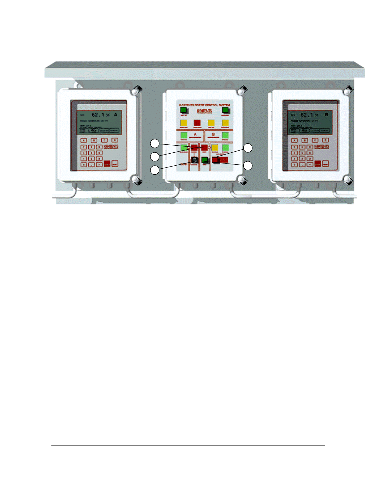
Figure 2.10 Complete Digital Divert Control System DD-01
The system consists of the following parts (Figure 2.10): Two K-Patents Process Refractometers PR-01-S (A
& B) are installed in series in the main black liquor line. Each refractometer is complete with a Sensor, an
Indicating transmitter and Interconnecting cables. Each refractometer provides also a 4-20 mA % solids output
signal not used by the divert control system.
The Divert Control Unit DD-01 is contained in one enclosure with the same dimensions as the refractometer
Indicating transmitter enclosure. The control unit includes:
- an operator panel
- control logics
- contact outputs for prism wash, warnings, alarms and black liquor diversion
- Two isolation valves HIMP-2 (optional) for the refractometers above to allow removal of
the refractometers from a pipe with full flow and pressure. The isolation valve includes a
prism wash nozzle and two check valves (one for prism wash, one for stuffing box flush).
- A roofed mounting plate to mount the two Indicating transmitters and the Divert Control
Unit together.
- Two steam valves with steam traps for prism wash (pneumatic + solenoid valves).
- Two hand valves (one for prism wash, one for stuffing box flush).
- One alarm horn (supplied by the customer).
Note. BLRBAC (The Black Liquor Recovery Boiler Advisory Committee) recommends a spare sensor to be
maintained in stock on-site.
INSTRUCTION MANUAL FOR DD-01 DOCUMENT/REVISION: IMD 1/5
Effective: June 20, 2005
Page 4
3
2.2. OPERATOR PANEL
3
4
5
7
6
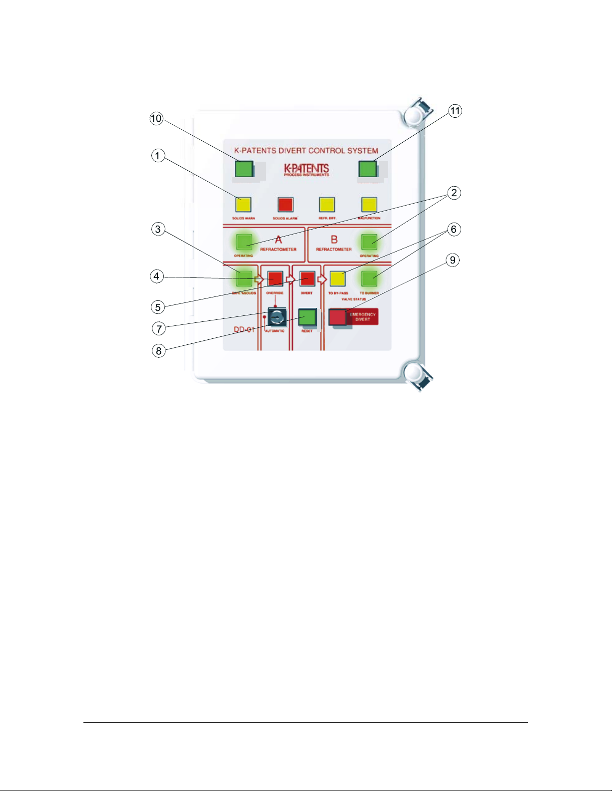
Figure 2.20 The operator panel.
The operator panel has a clear layout and the operator can see all information at one glance. The divert decision is controlled from the operator panel which provides doubled security, since all information is simultaneously shown both as LED indication in the Divert Control Unit and as a diagnostic messages in the Indicating
Transmitters (Figure 2.20).
Each refractometer has a green OPERATING light (1), so the operator knows when he can rely on the refractometer measurement. A refractometer will influence the divert decision only when the green OPERATING
light is on. A malfunctioning refractometer is automatically taken out of operation. One green indicator light
SAFE% SOLIDS (2) is based on the two refractometers and the divert decision rules (Section 5.7).
One red DIVERT light (3) that will be switched on when the SAFE% SOLIDS goes off. The DIVERT light
indicates divert status of the divert relay. The divert relay has an output switch contact, for use in the Black
Liquor Firing Tripping Logic. The relay is OFF in the DIVERT position, because a power failure will give a
DIVERT decision.
A lockable OVERRIDE/AUTOMATIC switch (5) and a red OVERRIDE warning light (4) is ON always if
switch in OVERRIDE position. If the SAFE% SOLIDS goes OFF and this switch is in the OVERRIDE position, then the OVERRIDE light is lit instead of the DIVERT light. One RESET push-button (6) for the
DIVERT action. The DIVERT action always has to be manually reset. If the override switch is in Automatic
position and SAFE% SOLIDS is off, the DIVERT action cannot be reset.
One EMERGENCY DIVERT push-button (7) to manually initiate DIVERT in an OVERRIDE or emergency
situation. The DIVERT light is lit also after manual divert action. The EMERGENCY DIVERT button has a
protective hinged cover, to prevent inadvertent use.
Two indicator lights (8) for the divert valve status TO BY-PASS/TO BURNER from microswitches on the
valve. For intermediate valve positions both lights are off.
A row of four alarm lights (9) that indicate black liquor SOLIDS WARNING (at 60%), black liquor SOLIDS
ALARM (below 58%), refractometer reading more than 2% absolute difference and refractometer malfunction.
INSTRUCTION MANUAL FOR DD-01 DOCUMENT/REVISION: IMD 1/5
Effective: June 20, 2005
Page 5

4
A light test button (10) switches all 11 lights on. An alarm reset button (11) resets the alarm lights. For normal
operation the operator panel has four green lights on (A OPERATING/B OPERATING/ VALVE TO
BURNER/SAFE% SOLIDS).
2.3. ALARMS
The divert control system has four alarms, audible and indicating:
1. Black liquor SOLIDS WARNING, yellow light (60% or below)
2. Black liquor SOLIDS ALARM, red light (58% or below)
3. Refractometers reading more than 2% absolute DIFFERENCE, yellow light
4. Refractometer MALFUNCTION, yellow light
The alarms 1, 2 and 4 are initiated by either refractometer. System contains also optional alarms, see wiring
drawing 3.11.
The operator panel contains four indicator lights and an ALARM RESET button. The reset button will silence
the audible alarm, but the visual indication will remain until the condition has returned to normal.
To avoid unnecessary alarms the following interlocks are implemented:
- A refractometer can initiate an alarm only when it is operating.
- Alarm 4 can be initiated only if both refractometers are operating.
The parameters (2%, 58% and 60%) are default settings, which can be changed from the Indicating transmitter
keyboard (Sections 5.3 and 5.4). The parameter for 2% can be decreased and the parameter for 58% and 60%
can be increased.
2.4. PRISM WASH
For K-Patents Process Refractometer, the need of prism wash is reduced and even in some cases eliminated.
The prism keeps clean due to the probe design features:
- The prism is flush mounted in a surface deflecting the black liquor main flow, which causes
a strong mechanical cleaning action.
- The prism has the same temperature as the black liquor.
In any case, however, an automatic regular prism wash provides an efficient check that the refractometer reacts. A steam wash of 3 seconds every half hour should be sufficient. Automatic single (one-of-two) diversion
will occur if either of the refractometers is in wash cycle.
The Divert Control Unit contains two relays for prism wash, WASH A and WASH B. To follow the BLRBAC
recommendation not to wash both prisms at the same time, there is an interlock. If both refractometers try to
wash simultaneously, one will display "WAIT" and perform the wash when the other has finished.
K-Patents recommends to use a steam trap instead of preconditioning valve to remove condensate from the
steam line. The wash times can be seen pressing soft keys "Display"/"System configuration"/"Wash times". To
change the wash times, see Section 5.6.
INSTRUCTION MANUAL FOR DD-01 DOCUMENT/REVISION: IMD 1/5
Effective: June 20, 2005
Page 6
5
2.5. MASTER DIVERT CONTROL UNIT
Figure 2.50 Operator’s panel and functions of the master divert control unit in the field with LED
indications.
1. Black liquor SOLIDS WARNING (at
60%), Black liquor SOLIDS ALARM (below 58%), Refractometer reading more than
2% absolute difference, and Refractometer
malfunction).
2. Each refractometer A and B has an
OPERATING green light, A refractometer
will influence the divert decision only when
the green OPERATING light is on. A malfunctioning refractometer is automatically
taken out of operation.
3. One green indicator light SAFE%
SOLIDS, based on the two refractometers
and the divert decision rules.
4. A red OVERRIDE warning light is on
always if the override switch is switched on.
5. One red DIVERT light that will be
switched on when the SAFE% SOLIDS
goes off. The DIVERT light indicates divert
status of the divert relay.
6. Two indicator lights for the divert valve
status. TO BY-PASS/TO BURNER from
microswitches on the valve. For intermediate valve positions both lights are off.
7. A lockable Override/Automatic divert
switch
8. A DIVERT RESET push-button.
9. An EMERGENCY DIVERT push-button.
10. A light test button switches all 11 lights
on.
11. An alarm reset button resets the alarm
lights.
INSTRUCTION MANUAL FOR DD-01 DOCUMENT/REVISION: IMD 1/5
Effective: June 20, 2005
Page 7
6
2.6. INDICATING TRANSMITTERS
An Indicating transmitter in a Divert Control System is identical (both hardware and software) to a standard
transmitter described in the PR-01-S Instruction manual.
1
3
2
CONC
PROCESS TEMPERATURE
TEST
109.3
In divert co ntrol operation
Removed
Start
fro m d iv
prism
wash
A
7
4
1
0
C a lib ra te
control
B
8
9
56
2
3
.
-
22.1
A
°C
Display
D
C
K-PTENTS
PROCESS INSTRUMENTS
RESET
ENTER
5
4
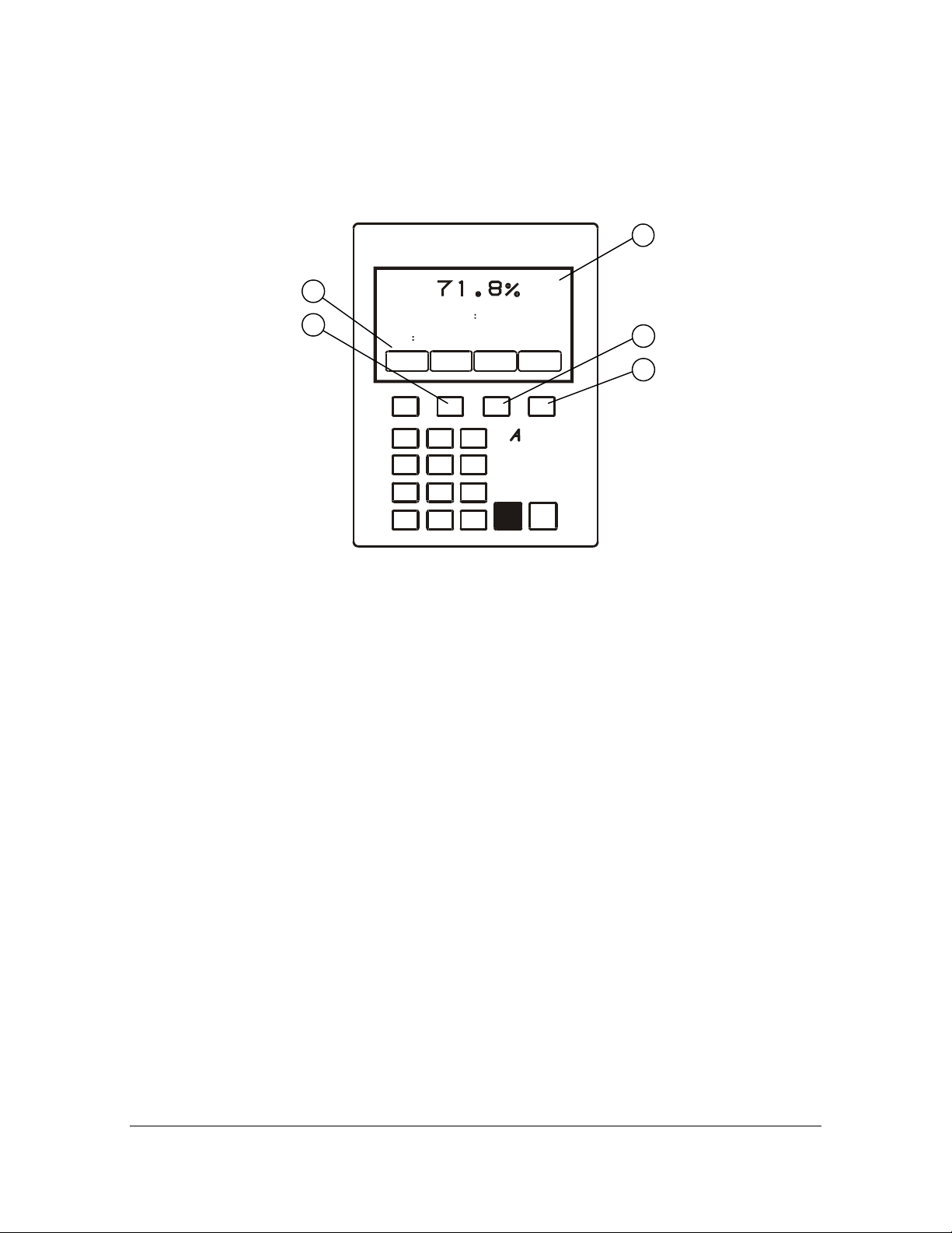
Figure 2.60 The Indicating transmitter.
The display, Figure 2.60, will give the following additional information pertinent to the Divert system:
1. A or B in the upper right corner indicates that the
transmitter is OPERATING in the divert system as refractometer A or B, Figure 2.10. If a or b is displayed
instead, the refractometer is removed from divert control operation. (If the upper right corner is empty, see
Section 5.2). For A or B the corresponding green
OPERATING light, Figure 2.20, is on, for a or b it is
off.
If you see a ? in this corner, see Section 5.2.
2. A softkey (B) defined by "Remove from divert control"
or alternatively "Restore to divert control". The visible
effects of pressing "Remove" for refractometer A is
that the soft key changes to "Restore", A switches to a,
and the green OPERATING light goes off. Further the
"Remove" soft key disappears from refractometer B,
because B must not be removed if it is the only refractometer in operation.
Note. Always press "Remove" for a refractometer before making service or switching the power off.
3. The "Normal operation" message is substituted by
"In divert control operation" or "Removed from divert control". Those messages may change to "Solids warning" or "Solids alarm" at low solids. An additional error message may occur: ** Divert control
fault ** combined with a ? in the upper right corner,
see Section 6.3.
4. The softkey "Display" (D) leads via "System configuration" (C) to "Divert control system" (D) which
gives the following information:
Refractometer difference alarm limit in % solids
Solids warning limit in % solids (default
value 60%)
solids alarm limit in % solids (default value 58%)
Divert rule and SW1/SW2 positions (Section 5.7)
5. The softkey "Calibrate" (C) gives possibilities to set
up for divert control and calibration, see Chapter 5.
INSTRUCTION MANUAL FOR DD-01 DOCUMENT/REVISION: IMD 1/5
Effective: June 20, 2005
Page 8

7
2.7. K-PATENTS DIGITAL DIVERT CONTROL UNIT SPECIFICATIONS
Model: DD-01
Enclosure: IP66 Nema 4X, dimensions 226 x 267 mm (8.91 x 10.5 in)
Supply: 24 V DC, provided by the Indicating transmitters
Ambient temperature: max 45 °C (113 °F)
Accessory: Roofed mounting plate for the Divert Control Unit and 2 Indicating
transmitters, Figure 2.60.
Material: AISI 316, dimensions 916 x 488 mm (36 x 19.2 in)
Figure 2.70 Divert Control Unit Mounting Plate: Dimensions (mm/in)
Figure 2.71 Divert Control Unit and Indicating Transmitter Enclosures: Dimensions (mm/in)
INSTRUCTION MANUAL FOR DD-01 DOCUMENT/REVISION: IMD 1/5
Effective: June 20, 2005
Page 9
8
3. MOUNTING
For mounting of the process refractometer and the isolation valve, consult the separate Refractometer
PR-01-S(-EX/FM) Manual.
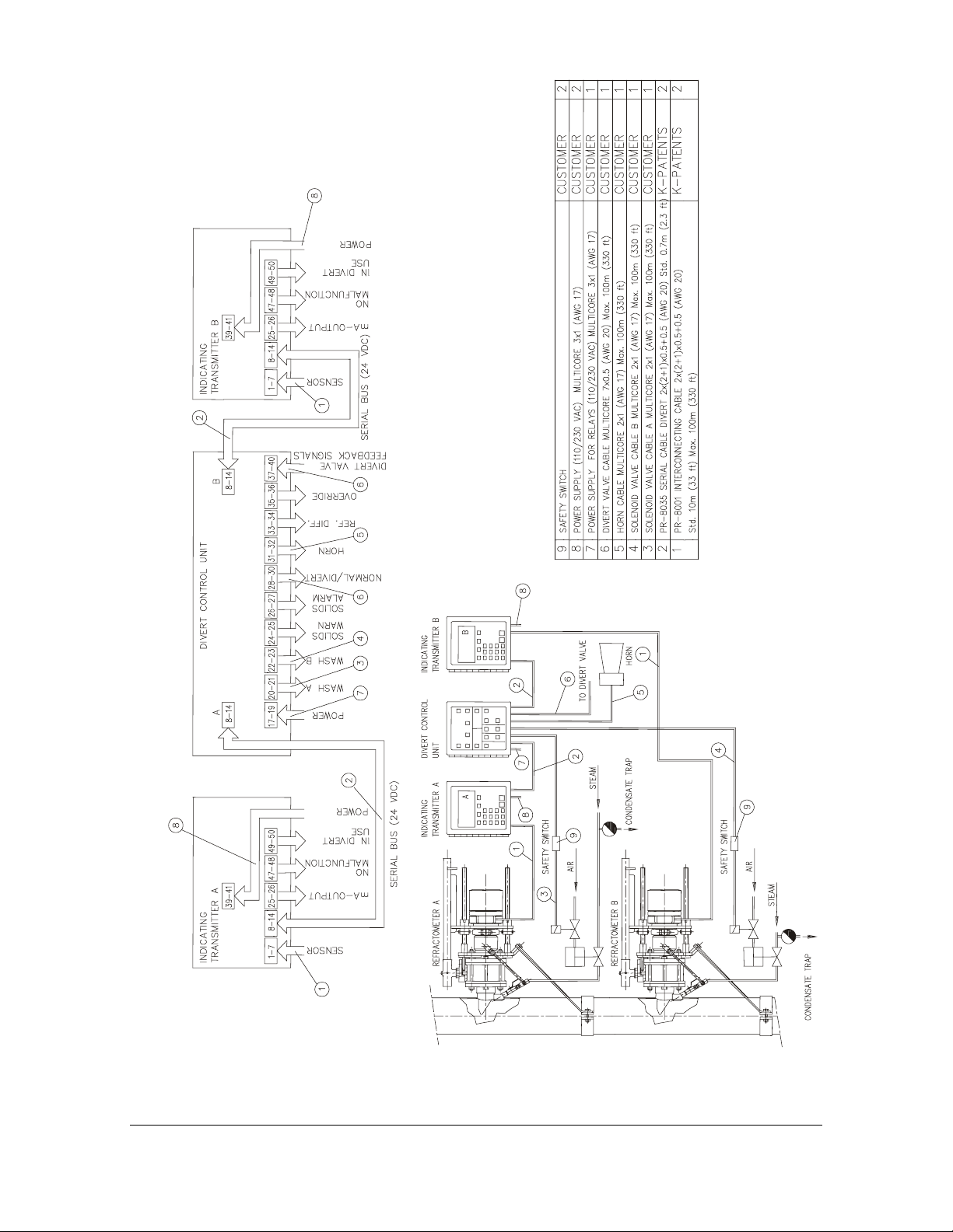
3.1. WIRING
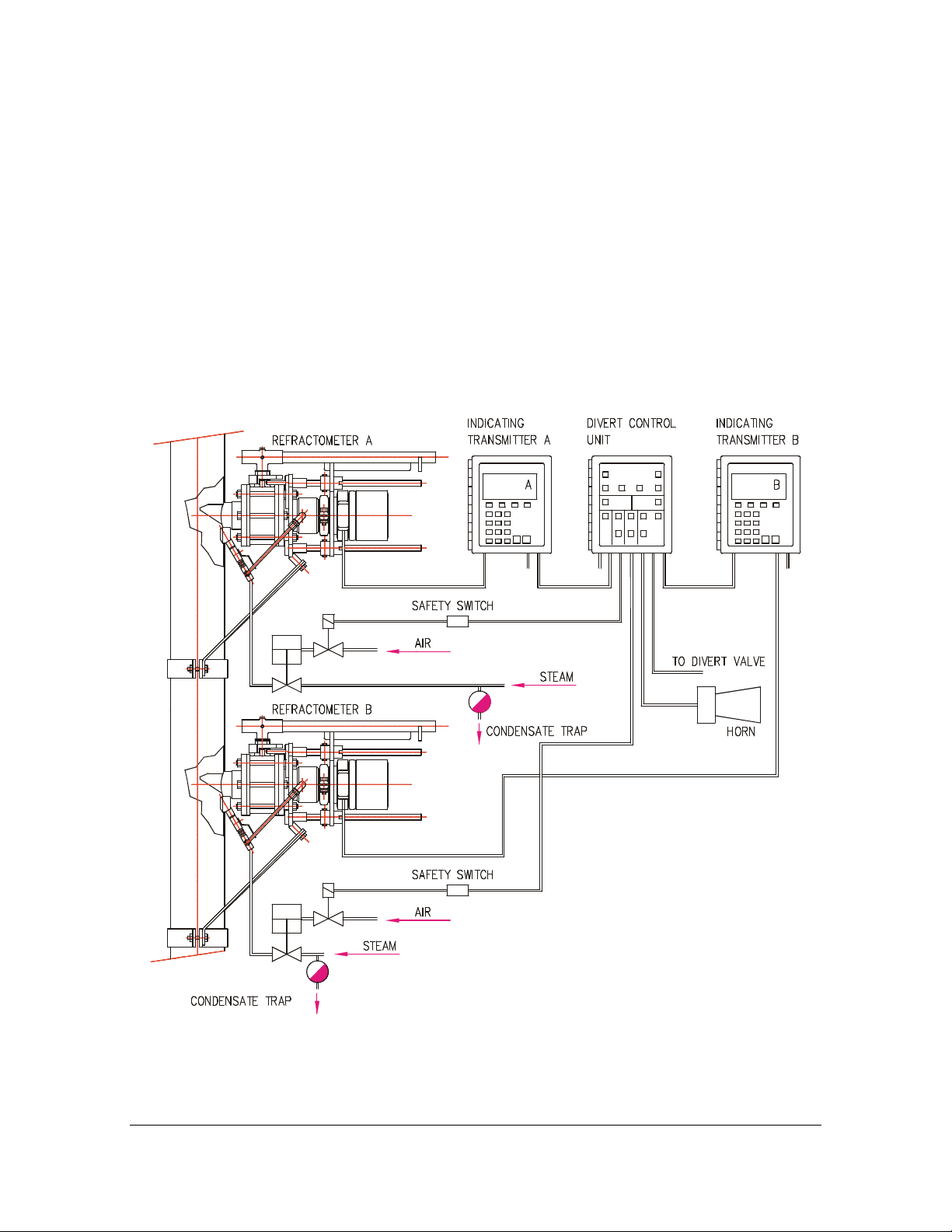
Wiring for the complete system, see Figure 3.10 and Figure 3.11 which describe also all cables and how each
cable is connected.
The cables 1 and 2 are included in the delivery. The terminal strip positions of the Divert Control Unit are
specified in Figure 3.11 and Figure 3.12.
Figure 3.10 Divert Control System Wiring Cables and Connections
INSTRUCTION MANUAL FOR DD-01 DOCUMENT/REVISION: IMD 1/5
Effective: June 20, 2005
Page 10
9
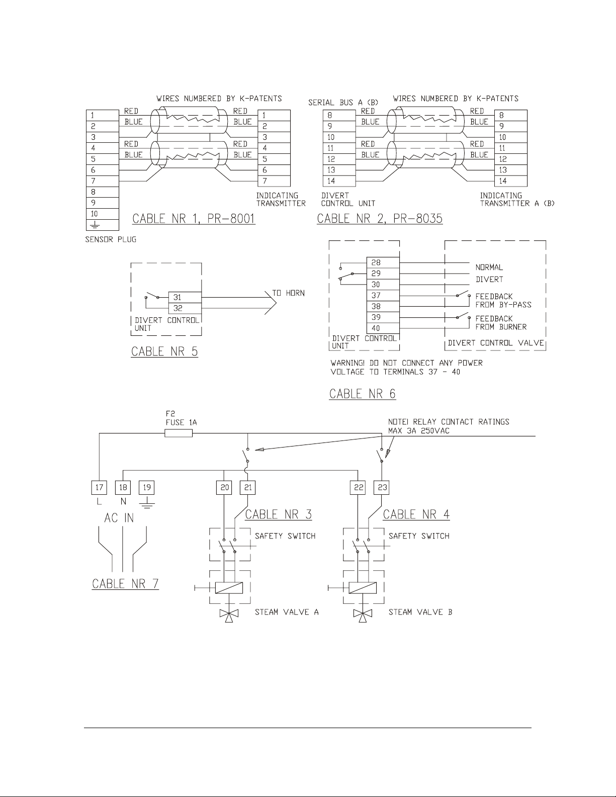
Figure 3.11 Divert Control System Wiring and Connections
INSTRUCTION MANUAL FOR DD-01 DOCUMENT/REVISION: IMD 1/5
Effective: June 20, 2005
Page 11
10
Figure 3.12 Cable connections
INSTRUCTION MANUAL FOR DD-01 DOCUMENT/REVISION: IMD 1/5
Effective: June 20, 2005
Page 12
11
RN1
C43
C1
R2
C2
R3
C3
R4
C4
R5
C5
R6
C6
J1
L1
R1
R14
C18
C19C20
C46
K4
C44
C47
IC30
K-PATENTS PR-7310 Rev.C
F2
C8
IC2
IC1
R15
D2
1A
C7
C45
V1
D1
C48
C49
C9
C10
C23
1
IC11 IC10
IC12
RN4
IC13
RN5
C21
IC14
F1
1A
RE1 RE8RE7RE6RE5RE4RE3RE2
V2
IC15
D15
IC16
D16
V3
IC3
C11
IC5IC4
C24
C22
R16
V4
K7K6K5 K14
DIVERT CONTROL UNIT
RN2
C12
IC6
C13
IC7
C14
X1
R7
C25
C26
D10 D12
K1 K2
C27
IC17
D5
IC8
IC18
D7
C28
C29
R8
C30
IC19
D6
SW
D8
X2
87654321
IC22
SW1
C16 C15
C31 C33
IC23
R10
R9
C17
IC9
IC20IC21
RN7
C37
D13D11
14 1413 1312 1211 1110 109988
D17
D18
D26D25D24D23D22D21D20D19
R24R23R22R21R20R19R18R17
V6
V5 V9
K8 K13
V7
V8
K11K10
K12K9
TP1
+5V
D3
RN3
D4
IC24
J2
RN6
C32
IC27
D14
C35
D9
C52
C39
C34
IC26
C38
K3
1615
EXT24VSERIAL BUS BSERIAL BUS A
D27 D28
C50
R25
R26
D29
D30
D31
63mA 63mA
F3 F4
R28
TP4
D32
TP3
TP2
C36
C40
C41
R12
R13
C42
C51
GND
IC25
R11
SGND
IC28
IC29
R27
SWGND
VALVE
37 403938363534333231302928
BURNERBYPASS
L
N
AC-POWER
27191817 26252423222120
WARN.
SOLIDS
ALARM
NORM.
DIVERT
A
B
SOLIDS
HORNWASH WASH
REF.DIFF.
OVERRIDE
POSITION
DANGER HIGH VOLTAGE
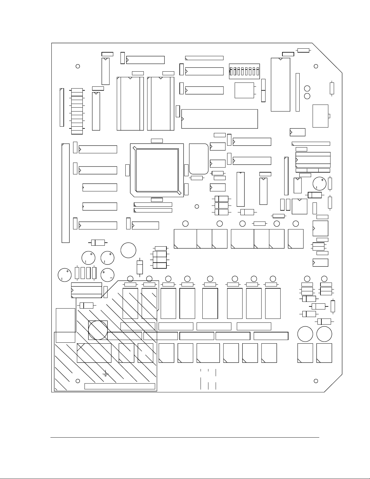
Figure 3.13 Divert control circuit board, layout.
INSTRUCTION MANUAL FOR DD-01 DOCUMENT/REVISION: IMD 1/5
Effective: June 20, 2005
Page 13

12
4. START-UP
For refractometer start-up consult the separate Refractometer PR-01-S(-EX/FM) Manual and the Mounting
and start-up check list.
4.1. DIVERT CONTROL UNIT START-UP
1. Check the wiring and supply voltage.
Note: Before the power is switched on, the DIVERT output relay is in DIVERT position.
2. Switch the power on for both Indicating transmitters.
The control system is now in the DIVERT mode, and the red DIVERT light is on.
3. Press the LIGHT TEST button. All eleven lights should switch on.
4. The upper right corner of the Indicating transmitter displays should now state a or b respectively. If
not, see Section 5.2.
If the message is "Removed from divert control" the refractometer is ready to "Restore to
divert control", softkey B.
If the message is "Solids warning" or "Solids alarm" then "Restore" provokes an alarm.
Press the ALARM RESET button.
For any other message, see Section 6.3.
5. Observe that the VALVE STATUS lights follow the position of the valve.
Now the Divert Control System is set for normal monitoring operation.
6. Check that the prism wash is working. Press the "Start prism wash", softkey A.
7. When the SAFE % SOLIDS has turned on and also the other conditions for safe boiler operation are
satisfied, the DIVERT can be turned off using the RESET button.
4.2. DIVERT CONTROL SYSTEM TRIMMING
During the trimming of a new system, it is recommended to keep the key in the OVERRIDE position.
When the key is in the OVERRIDE position, the DIVERT action has to be initiated manually using the
EMERGENCY DIVERT button. This should be done when the green SAFE %SOLIDS light turns off.
The trim procedures are described in Chapter 5, the measurement calibration in Section 5.1 and the prism
wash in Section 5.6.
The key should be turned to the AUTOMATIC position only after it has been decided that sufficient experience has been gained.
INSTRUCTION MANUAL FOR DD-01 DOCUMENT/REVISION: IMD 1/5
Effective: June 20, 2005
Page 14

13
5. CALIBRATION
The K-Patents Divert Control System is calibrated by the manufacturer. This chapter contains instructions how
to make the fine adjustment of the system.
5.1. REFRACTOMETER CONCENTRATION MEASUREMENT
For refractometer calibration consult also the separate Refractometer PR-01-S(-EX/FM) Manual.
The CONC% displays of the two Indicating transmitters have to show the same value. If there is a difference,
this can be eliminated by changing the Bias for one of the refractometers. Key in the sequence Calibrate / Parameters / CONC(RI) / Parameters / Bias. Comparison with sample determination can decide which one
should be corrected.
Example: If the Indicating transmitter of A displays CONC% = 63.2% and B displays CONC% = 63.8%, the
difference can be eliminated e.g. by lowering B by 0.6%. Read bias from the display of refractometer B. If
bias = 52.923 then enter a new bias = 52.323.
Due to its digital measurement principle, the readings of the K-Patents Process Refractometer do not drift by
time. Frequent recalibrations based on off-line moisture analysis must be avoided, as they will introduce random fluctuations to the refractometer readings.
If the concentration reading is noisy, the damping can be increased. Enter Calibrate / Parameters / CONC(RI) /
Damping time. The Damping time is the time in seconds for the signal to reach half of its final value after a
step change. Increase the damping time in small steps, and wait for the result.
5.2. REFRACTOMETER ACTIVATION FOR DIVERT CONTROL
When a refractometer is activated for Divert control, the upper right corner of the display shows alternatively
A, a, B, b or ?. If the corner is blank the divert function must be activated by pressing the sequence Calibrate/Parameters/Divert control/Divert control and select "1 Activated".
The program has to be version 4.0 or higher, otherwise "8 Divert control" is missing from the CALIBRATE
menu. The program EPROM has then to be changed to an up-dated version.
The decision to display A (a) or alternatively B (b) is not programmed, it depends on to which SERIAL BUS
port in the Divert unit (Figure 3.13) the Indicating transmitter is connected.
If a Divert activated refractometer is used in another type of application, the divert function has to be deactivated by selecting "0 Not activated". After de-activation all references to Divert functions disappear except "8
Divert control" in the CALIBRATE menu.
Note. If a message DIVERT CONTROL FAULT and a ? appear on the IT-R display, the reason is one of the
following:
1. Cables between the IT-R and the terminals 8-14 on the DD-01 are not properly connected. Re-
connect to fix.
2. Communication 485 component IC 17 (A) or IC 19 C (B) is broken on the PR-7310 board inside
the DD-01. Replace board.
3. Communication 485 component IC 1r is broken on the PR-7010 board inside the IT-R. Replace
board.
4. Dip switch 3. is in the “up” position which means that the PR-7310 card is configured to work in
the remote mode. Change the dip switch back to low (=off) position.
INSTRUCTION MANUAL FOR DD-01 DOCUMENT/REVISION: IMD 1/5
Effective: June 20, 2005
Page 15

14
5.3. SIGNAL DIFFERENCE ALARM
According to BLRBAC, if a difference of 2% solids (absolute value) or greater exists between refractometer
readings, an alarm shall be activated.
The alarm limit 2% can be changed from the keyboard using the sequence Calibrate/Parameters/Divert control/Ref. difference limit. If the deviation alarm trips seem too frequent, it may help to increase the signal
damping, Section 5.1.
Note. If the two refractometers have different limit values, the lower value is used by alarm system.
5.4. LOW ALARMS
The low alarm limits are set from the keyboard of the Indicating transmitter. Enter sequence Calibrate/Parameters/Divert control. The menu will show “3 Low conc warning limit” and “4 Low conc divert
limit”. The latter has a double function: Both LOW SOLIDS ALARM and DIVERT limit.
The Indicating transmitter display will carry the messages “Solids warning” and “Solids alarm” when the corresponding alarms occur.
Note. The alarm limits are set separately for the two refractometers. Each refractometer gives an alarm according to its own settings.
5.5. REFRACTOMETER MALFUNCTION ALARM
The built-in intelligent diagnostics of K-Patents Process Refractometer provides a tight control of the operation. A full test cycle is completed with an interval less than one second. A description of the microprocessor
implemented diagnostics is given below. For details consult the Instruction Manual of the refractometer PR01-S. Only errors classified as Equipment malfunctions will cause alarm and removal from the Divert control system. Process related faults will only cause a message in the Indicating transmitter display. See also
Section 6.3 for additional diagnostics.
The most important test is to check the signal coming from the digital image sensor during measurement. Improper function of light source, optical components, image sensor and sensor driver are recognized by this
test.
The compensation for temperature measurement is checked, both the temperature element and the A/D converter.
The cable between Sensor and Indicating transmitter is checked using a check sum method, thus recognizing
short circuits, open circuits and excessive disturbances.
The microprocessor system has also a self-checking test program to ensure the proper operation of the CPU
and the memories. The constants in the EEPROM memory are tested to be within strict limits of acceptance.
The performance of the microprocessor is of critical importance for the measurement control. A separate
hardware watch-dog circuit ensures the proper microprocessor operation by checking that the microprocessor
regularly sends out a predetermined pulse sequence. Another hardware circuit checks that the supply voltage
to the microprocessor is within safe limits, to prevent any brownout stray output pulses.
5.6. PRISM WASH
A prerequisite for a proper function of the divert system, is that the prism wash works. The TEST value in the
display should increase at least 20 steps during WASH, provided TEST is not close to its maximum value 248.
See Sections 8.1, 8.5 and 9.2 in PR-01-S Instruction Manual.
INSTRUCTION MANUAL FOR DD-01 DOCUMENT/REVISION: IMD 1/5
Effective: June 20, 2005
Page 16

15
WASH TIMES
The wash times can be seen by pressing Display/System configuration/Wash times. The values set at delivery
are the following:
Preconditioning = 0 seconds
Wash time = 3 seconds
Recovery time = 30 seconds
Interval = 20 min
The wash times are changed by pressing the sequence Calibrate/Parameters/Prism wash.
Note maximum wash time is 30 seconds and maximum recovery time 30 seconds.
WASH CHECK
This function can be defined from the prism wash menu: Calibrate/Parameters/Prism wash/Wash test. A prism
wash is accepted if:
a. TEST exceeds “TEST limit”
b. TEST increases more than “TEST difference”
The default values of “TEST limit” and “TEST difference” are zero (0), which makes the wash check inactive.
If the wash is not accepted, the diagnostic message will be “Prism wash failure”.
A “Wash retries” parameter can also be set to repeat the wash if the wash check fails. The default value is zero
(0).
WASH STOP
Wash stop function can be defined from the prism wash menu. Wash can be prevented when the process temperature is below the set limit, thus indicating that the pipe is not in use. To activate the “wash stop” key sequence: Calibrate/Parameters/1. Prism wash/Wash stop/1. Active and set the temperature limit.
The default value for wash stop is inactivate. When the wash is not accepted the diagnostics message is “Wash
stop/temp. limit”.
EXTERNAL WASH STOP
An input switch can be configurated to an external wash stop to prevent the prism wash when the corresponding input switch is connected. “External wash stop”-message will show when automatic wash is activated from
the soft keys. The input switch can be set to protect the refractometer e.g. if the process is stopped.
AUTOMATIC SINGLE DIVERSION CONTROL DURING PRISM WASH CYCLE
Automatic single (one-of-two) diversion control will take place if either of sensors are in prism WASH cycle.
5.7. DIVERT DECISION RULES
TWO REFRACTOMETERS IN OPERATION:
BLRBAC states the following: For the solids measurements, two refractometers in series must be used. When
both refractometers are in service, the requirement for an automatic black liquor diversion can be satisfied by
either of the following options:
1. If either refractometer reads dissolved solids content 58% (default) or below, an automatic
black liquor diversion must take place.
INSTRUCTION MANUAL FOR DD-01 DOCUMENT/REVISION: IMD 1/5
Effective: June 20, 2005
Page 17

16
2. When both refractometers read dissolved solids content 58% (default) or below, an auto-
matic black liquor diversion must take place.
Either option is satisfactory.
The rules are listed in decreasing order of security. Only rule 1 satisfies the high safety requirements set by
BLRBAC, August, 1982. On the other hand, the probability of false trips decreases with decreasing safety. It
means that if false trips are too frequent, the rule 2 may be preferred at the cost of safety. The rule 2 has later
been accepted by BLRBAC.
A third conceivable alternative is to base the decision on only one refractometer (the master) and use the other
refractometer (the slave) for comparison only (and difference alarm). Concerning security and false trips, this
rule is a compromise between rules 1 and 2.
The divert decision rule is selected by the switch SW on the divert control board (Figure 3.13). ON position is
upwards.
Switch SW
Rule
SW1 SW2
OFF OFF One-of-two (BLRBAC) Rule 1
ON OFF A master, B slave -
OFF ON B master, A slave -
ON ON Two-of-Two Rule 2
Table 5.70 Divert decision rule selection.
ONLY ONE REFRACTOMETER IN OPERATION:
When only one instrument is IN OPERATION the divert action takes place if this instrument reads 58 % or
below. The status of SW (Table 5.70) has no influence on the divert decision in this case.
NO REFRACTOMETER IN OPERATION:
If both instruments are out of operation (due to malfunction or maintenance), then according to BLRBAC
divert action must take place. See also Section 8.7 about external DC supply.
REMOTE DIVERT SWITCH CONFIGURATION
Switch SW Rule
SW 3
OFF DD-01 normal operation
ON Remote divert card activated
See Section 8.8.
See Section 5.2 if you have on the screen the message DIVERT CONTROL FAULT.
INSTRUCTION MANUAL FOR DD-01 DOCUMENT/REVISION: IMD 1/5
Effective: June 20, 2005
Page 18

17
6. MAINTENANCE
As the Divert Control System is a pure digital system, no special maintenance is needed. The LIGHT TEST
button on the operator panel (Figure 2.50) sends a signal to the microprocessor, and the microprocessor
switches all 11 LED lights on as long as the button is pressed. This way not only the lights but also the processing system is checked.
To assist the identification of a faulty component, the information flow and the circuit diagrams are given in
Sections 6.1 and 6.2. Also the logic diagrams of Chapter 7 may be of help.
6.1. INFORMATION FLOW
The power and information flow of the total Divert system is shown by Figure 6.10. Additional information
about the cable connections is found in Figures 3.10, 3.11 and 3.12.
Figure 6.10 Information and power flow.
INSTRUCTION MANUAL FOR DD-01 DOCUMENT/REVISION: IMD 1/5
Effective: June 20, 2005
Page 19

18
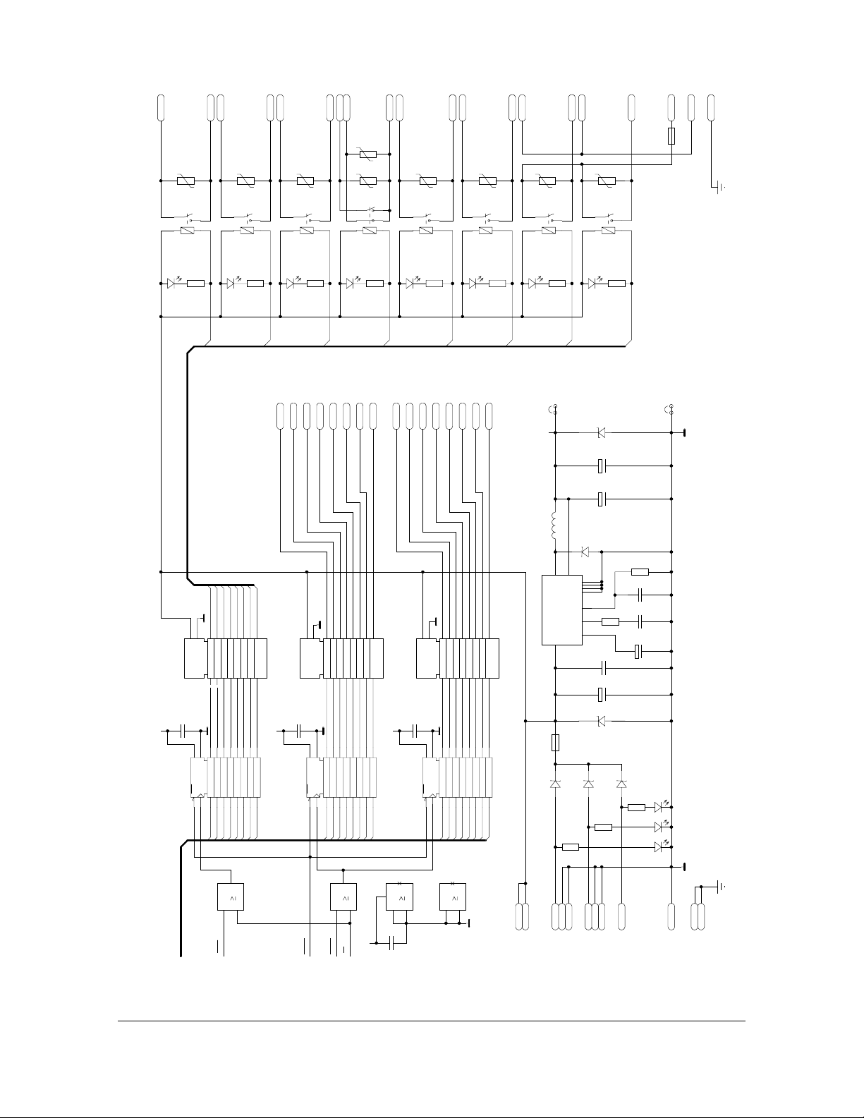
6.2. DIVERT CONTROL CIRCUIT BOARDS
The component lay-out of the divert control circuit board is shown by Figure 3.12 and the circuit diagram by
Figures 6.20 to 6.25.
Figure 6.20 Operator panel board, component layout.
Figure 6.21 Operator panel PR-7311 circuit diagram, page 2 of 2
INSTRUCTION MANUAL FOR DD-01 DOCUMENT/REVISION: IMD 1/5
Effective: June 20, 2005
Page 20

19
Figure 6.22 Operator panel PR-7311 circuit diagram, page 1 of 2.
INSTRUCTION MANUAL FOR DD-01 DOCUMENT/REVISION: IMD 1/5
Effective: June 20, 2005
Page 21
20
RD
WR
AD11
AD10
AD8
AD12
AD13
AD14
AD9
14
A14
A13
A12
A11
A10A9A8A7A6A5A4A3A2A1A0
2
232425
26
A13
A14
A11
A10
A12
8
1
IC2
HC32
9
10
AD15
IO8
IO7
IO6
3456789
A9
A8
A7
A6
11
IC2
12
12131516171819
IO5
IO4
IO3
IO2
IO1
32K x 8bit SRAM
55257
10 11
A5
A4
A3
A2
A1
+5V
40
1
IC8
HC32
VPPNCOECEA15
13
1
+5V
A0
100n
C11
+5V
1
2
28
IC5
W
CE
OE
1
202122
27
A15
6
1
14
IC2
HC32
4
5
7
100n
C8
1
2
+5V
100n
C10
+5V
14
28
IC4
A14
A13
WCEOE
1
202122
26
27
A15
A14
AD13
AD14
AD15
100n
C14
1
2
34567891012131415161718
30
11
O13
O14
O15
PGM
A14
2
A13
20
39
A18
A17
A15
A16
A14
IO8
IO7
A12
A11
A10A9A8A7A6A5A4A3A2A1A0
2
3456789
232425
A13
A9
A8
A7
A11
A10
A12
AD11
AD10
AD8
AD12
AD9
AD7 AD7
AD6 AD6
O8
O9
O7O6O5O4O3O2O1
O10
O11
O12
64K x 16bit EPROM
A12
A11
A10A9A8A7A6A5A4A3A2A1A0
A13
A9
A8
A7
A11
A10
A12
A0-9
12131516171819
IO6
IO5
IO4
IO3
IO2
IO1
32K x 8bit SRAM
AD0-15
55257
10 11
A6
A5
A4
A3
A2
A1
AD5 AD5
AD2 AD2
AD1 AD1
AD0 AD0
AD4 AD4
AD3 AD3
19
O0
27C210
2122232425262728293132333435363738
A6
A5
A4
A3
A2
A1
A18
A17
100n
C9
1
2
+5V
19
10
20
IC3
OC
2345678
1
11
RESET
RESOUT
CLOCKOUTCLKIN
A16
+5V
12131415161718
1Q
8Q7Q6Q5Q4Q3Q2Q
8D7D6D5D4D3D2D1DC
74HC573
9
AD16
AD17
AD18
AD19
45678910
11
15
16
29
30
RD
WR
DT
S0S1S2
ALE
BHE
UCS
DEN
LCS
LOCK
A15
100n
C13
1
2
19
10
20
1Q
IC7
OC
2345678
1
11
AD15
SDISP
SRLY
ISOSWISOSW
SSER2SSER2
19202124252627
P1.7
P1.6
P1.5
P1.4
P1.3
A13
A9
A8
A14
A11
A10
A12
12131415161718
9
AD11
AD10
AD8
AD12
AD13
AD14
AD9
AD17
AD18
AD19
28
A17
A18
A19
P1.2
P1.1
P1.0
100n
C18
1
2
+5V
20
8Q7Q6Q5Q4Q3Q2Q
IC10
8D7D6D5D4D3D2D1DC
74HC573
1
AD11
AD10
AD12
AD13
AD14
AD15
AD16
7980818283
A16
AD10
AD11
AD12
AD13
AD14
AD15
16bit MICROPROCESSOR
IC15
T0IN
T1IN
T0OUT
T1OUT
INT4
INT1
INT0
INT3
INT2
P2.7
P2.6
PEREQ
ERROR
READY
HOLD
HOLDA
RESIN RESOUT
OSCOUT
PDTMR
36
37 383940
41 44
8
OUT
Osc.
X1
32.0MHz
VCC
N.C.
GND
1
7
14
12
+5V
3K32
R7
12
+5V +5V
NCS
NMI
TEST
12
13
14
17
18
60
RN5
RN5
RN5
10K0
13
14
12
100n
C26
1
2
RN1
10K0
RESET
IC18
MAX699
WDI
VCC
10R0
1
23467
R8
12
+5V
3
454647
RN4
10K0
RN4
RN4
15
14
16
+5V
8
GND
48
RN5
RN5
RN4
RN5
18
16
13
17
P2.5
3132333435
49
50
5455565758
10K0
RN5
RN5
15
19
INT1
CTS0
P2.0
P2.4
P2.2
P2.1
P2.3
515253
59
RXD1
TXD1
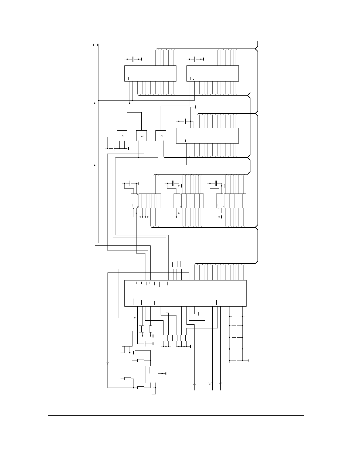
Figure 6.23 Divert control board PR-7310 circuit diagram. Page 1 of 3.
A7
19
10
1Q
OC
2345678
11
AD8
AD7 AD7
AD9
AD7
AD8
AD9
TXD0
RXD0
RXD0
TXD0
A6
A5
A4
A3
A2
A1
A0
12131415161718
8Q7Q6Q5Q4Q3Q2Q
8D7D6D5D4D3D2D1DC
74HC573
9
AD5 AD5
AD2 AD2
AD1 AD1
AD0 AD0
AD4 AD4
AD3 AD3
AD6 AD6
616266676869707172737475767778
AD0
AD1
AD2
AD3
AD4
AD5
AD6
80C186EB
VSS
VCC
8465
6343
22
6442
23
2
1
100n
C22
1
2
100n
C24
1
2
100n
C23
1
2
100n
C25
1
2
+5V
INSTRUCTION MANUAL FOR DD-01 DOCUMENT/REVISION: IMD 1/5
Effective: June 20, 2005
Page 22

21
(8)
(9)
K1A2
K1A1
A
SER0-
SER0+
D7
SA5.0
1
2
D6
SA5.0
1
2
100n
+5V
IC17
VCC
ROREDE
123
RXD0
+5V
3
IC2
1
C27
1
2
678
DO
DO
GND
LTC485
DI
45
TXD0
1k00
15
RN3
14
RN3
D10
1
2
43
1
1
IC23
1k00
13
D4
RN3
1
2
12
D3
RN3
1
2
100n
C28
1
2
20
10
IC20
R1DC1
CLR
CP
1118137144173
1
HC32
2
100n
C7
+5V
1
2
20
10
EN
IC1
&
G2
1192345678
IC28
C40
1
+5V
DC/DC
R27
R26
RD
ISOSW
C41
1
1
45
VCC
GND
conv.
NME0505D
VOUT
0V
7
100n
2
500R
12
500R
12
F3
12
BYPASS
X13 1
WR
RESET
(9)
(10)
K2A2
K1A3
B
SER1-
+5V
DO
VCC
IC19
ROREDE
123
RTS
D12
1
2
65
1
IC23
74HC05
9126155162
1Q2Q3Q4Q5Q6Q7Q
1D2D3D4D5D6D7D
AD2AD2
AD1AD1
AD0AD0
AD3 AD3
AD4 AD4
18171615141312
Y1Y2Y3Y4Y5Y6Y7
A5A3A4A6A7
A1A2G1
KN2
KN1
KN3
1K
R12
R13
100n
1K
2
8
VCC
IC29
123
D27
F4
12
BURNER
X13 2
X14 1
(8)
(10)
K2A3
K2A1
SER1+
D5
SA5.0
1
2
D8
SA5.0
1
2
100n
C30
1
2
678
DO
GND
LTC485
DI
45
TXD1
1
74HC05
19
8Q
HC273
8D
18
AD7AD7
AD6AD6
AD5AD5
AD0-18
11
Y8
HC541
A8
9
KN6
KN5
KN4
12
12
C42
1
765
VO1
VO2
GND
Opto-isol.
1+1-2-
2+
4
D28
12
12
1
1
1
C50
R28
R25
3K3
3K3
2
2
1
D29
2
D32
1N4007
X14 2
2
SA5.0
1
100n
2
HCPL2731
C51
1
2
100n
1
2
+5V
D30
SA5.0
D31
C12
1
IC6
1
100n
2
2
1N4007
1
100n
2
20
10
EN
&
G2
1192345678
SWGND
TEST POINT
2
TP4
5VSER
D9
SA5.0
1
2
100n
C39
1
2
7
0V
VOUT
IC27
NME0505D
VCC
GND
conv.
DC/DC
1
45
100n
C38
1
2
100n
C37
+5V
1
2
AD9
AD8
AD15
AD14
AD13
AD12
AD11
AD10
18171615141312
11
Y1Y2Y3Y4Y5Y6Y7
Y8
HC541
A5A3A4A6A7
A8
A1A2G1
9
DIP1
DIP2
DIP3
DIP4
DIP5
DIP6
DIP7
DIP8
3K32
12
RN2
+5V
13
RN2
14
RN2
15
RN2
16
RN2
17
RN2
18
RN2
19
RN2
SW1
1234567
100n
C32
1
2
100n
C34
1
2
100n
C36
1
2
7
161718
OFF
VCC
GND
+9V
-9V
POWER
IC25
C1+
C1-
C2+
C2-
LT1180
23456
100n
C35
100n
C33
1
2
1
2
RN6
15
RN6
13
RN6
14
RN6
12
1K0
123
4
1+1-2-
2+
VO1
VO2
VCC
765
8
1K0
RN7
RN7
RN7
RN7
33pF
C15
1
2
33pF
C16
1
2
100n
C17
1
2
7
21
X1
VCC
VSS
IC9
D0D1D2D3D4D5D6D7A0A1A2
123
252627
28
AD3
AD2
AD1
AD4
AD0
KN2
KN1
KN3
12
R1
100R
12
R2
12
RN1
RN1
RN1
RN1
RN1
RN1
3K32
OVERRIDE
LAMP TEST
ALARM RESET
J1 12
J1 10
Opto-isol.
GND
R3
J1 14
IC24
+5V
12
13
14
15
X2
12
18.432MHz
+5V
+5V
12
13
14
15
16
17
10111213141516
SW8
89
J26
J23
J25
UARTS
UACTS
910
15
R
R
T
12
13 14
CTSI
RXDI
RTSI
R11
12
10R0
765
8
VO1
VCC
IC26
1+1-2-
HCPL2731
123
RTS
RXD RD
TXD
CTS
INT1
15169
86513101411
X2
RI
TXD
INT
RXD
RTS
DTR
82510
4
22232420191817
A1
A2
A3
AD7
AD6
AD5
KN6
KN5
KN4
C1
1
2
C2
1
2
C3
1
2
C4
1
2
C5
1
2
12
R4
C6
1
2
12
R5
12
R6
DIVERT RESET
EMERGENCY DIVERT
J1 46
J1 44
J1 40
SD
8
11
TXDI
CTS
RD
J22
T
100n
100n
100n
100n
100n
100n
C52
1
12
DSR
DCD
WRCSRESET
J24
J21
SGND
SGND
TEST POINT
1
2
TP3
100u
2
VO2
GND
Opto-isol.
2+
HCPL2731
IC23
A1-3
1213
IC23
14
1
1
74HC05
7
1
2
100n
C31
1011
1
1
IC23
74HC05
89
1
1
IC23
74HC05
21
1
1
74HC05
WR
RD
SSER2
RESOUT
4
+5V
AD0-15
Figure 6.24 Divert control board PR-7310 circuit diagram. Page 2 of 3.
INSTRUCTION MANUAL FOR DD-01 DOCUMENT/REVISION: IMD 1/5
Effective: June 20, 2005
Page 23
22
5
E
K41
5
1
A WASH
V1
. .
RE1
K52
12
..
F2
1A
L
12
8
16
N
K91
K93
HORN
V7
5
RE6 RE7
1
K102
. .
12
5
8
12
1
16
K121
K111
K122
NO MALF.
V9
. .
8
5
1
RE8
5
1
16
K101
K112
REF. DIFF
V8
. .
12
8
16
K81
K92
DIVERT/NORM
V6
. .
12
V5
. .
12
8
5
9
RE5
1
16
K71
K82
SOLIDS ALARM
V4
. .
12
8
5
RE4
1
16
K61
K72
SOLIDS WARN.
V3
. .
12
8
5
RE3
1
16
K51
K62
B WASH
V2
. .
12
8
RE2
16
LIN
K42
K43
P
D26
12
VIO24V
RE1-8
VIO24V
IC22
V
C29
.
+
1
IC21
AD0-18
4K7
R24
12
RE1
RE1
9
10
GND
DCOM
1234567
100n
.
2
10
20
2569121516
CP
CLR
111347
AD0
D25
12
RE6
RE5
RE2
RE3
RE4
Q0Q1Q2Q3Q4Q5Q6
1Q2Q3Q4Q5Q6Q7Q
1D2D3D4D5D6D7D
8
131417
AD5
AD1
AD3
AD2
AD4
3
1
IC16
1
2
SRLY
RE8
RE7
12131415161718
D6D5D4D3D2D1D0
19
18
AD6
AD7
HC32
4K7
R23
RE2
Q7D7
811
8Q
HC273
8D
D24
12
12
J119
J121
WARN
ALARM
REFRDIF
VIO24V
IC12
ULN2803A
100n
C19
.
+5V
1
2
IC11
J120
DCOM
20
111347
RESET
4K7
R22
12
RE3
J122
AOPER
MALFUNC
Q0Q1Q2Q3Q4Q5Q6
GND
1234567
.
10
2569121516
1Q2Q3Q4Q5Q6Q7Q
CP
1D2D3D4D5D6D7D
CLR
AD1
AD0
IC16
J125
AD2
4
SDISP
D23
12
J126
SAFE
BOPER
8
131417
AD3
AD4
6
1
5
WR
J127
J129
OVERRIDE
12131415161718109
Q7D7
D6D5D4D3D2D1D0
811
19
8Q
8D
18
AD5
AD6
AD7
HC32
+5V
4K7
R21
12
RE4
J128
DIVERT
VBYPASS
ULN2803A
.
+5V
HC273
8
14
1
IC16
9
10
100n
C21
.
.
1
2
D22
12
J130
IC13
C20
1
7
J132
OUT4
BURNER
VIO24V
GND
DCOM
100n
.
2
10
20
IC14
CLR
111347
HC32
4K7
R20
12
RE5
J135
J137
OUT5
OUT6
Q0Q1Q2Q3Q4Q5Q6
1234567
2569121516
1Q2Q3Q4Q5Q6Q7Q
CP
1D2D3D4D5D6D7D
8
AD8
AD9
AD11
AD10
11
1
IC16
12
13
J136
131417
AD12
D21
12
J138
OUT7
AD13
AD14
HC32
OUT8
12131415161718109
D6D5D4D3D2D1D0
811
19
18
AD15
4K7
R19
J139
Q7D7
ULN2803A
8Q
HC273
8D
D20
12
12
RE6
+5V
L1
IC30
F1
VIO24V
J1 49
J1 47
4K7
R18
12
RE7
TP1
+5V
12
TEST POINT
.
.
..
12
150uH
D2
.
1
10
2
13
FB
VOUT
GND
4
OSC
L4962
SS FRC
VIN
7
.
VIO24V
1A
..
12
.
.
12
D16
D17
1N4007
.
.
4K7
R16
1
2
SR224V
SR124V
K1C 1
K1B 1
K1B 2
(13)
(12)
(11)
A
14
15 11
K2B 1
(11)
D19
D1
1
C44
1
C45
1
BYV27/50
2
512
.
C48
1
D15
1
2
C49
12
12
2
2
+
2
+
.
12
33nF
1
2
100u
2
+
SA26
2
1N4007
1N4007
4K7
R9
K2C 1
K2B 2
(13)
(12)
B
4K7
R17
12
RE8
SA5.0
220u
.
220u
.
12
C46
.
1
15K0
R15
C47
.
1
C43
.
1
+
.
.
.
12
D18
.
1
EXT24V
K3 1
(15)
TP2
4K64
R14
2n2
.
2
33n
.
2
2u2
.
2
4K7
12
R10
1
2
1
2
1
2
GND
GND
12
TEST POINT
D14
D13
D11
P
K3 2
K2C 2
K1C 2
(16)
(14)
(14)
B
A
Figure 6.25 Divert Control board PR-7310 circuit diagram. Page 3 of 3.
INSTRUCTION MANUAL FOR DD-01 DOCUMENT/REVISION: IMD 1/5
Effective: June 20, 2005
Page 24

23
6.3. DIAGNOSTIC MESSAGES
For diagnostic messages in the Indicating transmitter display, see the PR-01-S manual. The following messages appear only in divert systems:
- "In divert control operation" or "Removed from divert control", Section 2.6.
- "Solids warning" and "Solids alarm", Section 5.4.
- ** Divert control fault **
This message indicates that there is no communication to the divert control unit, probably cable error, Figure
3.12, cable 2.
If the instrument is not applied in a divert control system, de-activate the divert function, see end of Section
5.2.
Further the message ** Relay unit fault ** may appear. This indicates that the Relay unit PR-7080 functions
are defined, but no Relay unit is connected. Normally a Relay unit is not used in a Divert system because the
wash contacts are in the Divert control unit. Clear the relay functions by the key sequence Calibrate/Relay unit
and select an "0 Not Defined" for all four relays. For using an optional relay unit, see PR-01-S Manual, section 9.1.
6.4. DIAGNOSTIC LIGHTS
The Divert circuit board, Figure 3.12, contains the following diagnostic LEDS:
D3 Processor cycles: should flash
D4 Processor reads serial bus: should flash
D10 Serial bus A input: should flash
D11 On if 24 V DC supply from A is OK
D12 Serial bus B input: should flash
D13 On if 24 V DC supply from B is OK
D14 On if external 24 V DC is applied
D19 Wash relay A on
D20 Wash relay B on
D21 Solids warning relay on
D22 Solids alarm relay on
D23 Divert relay on = not DIVERT (Section 2.2)
D24 Horn on
D25 Refractometer difference relay on = difference alarm
D26 Override
D27 Valve to bypass
D28 Valve to burner
INSTRUCTION MANUAL FOR DD-01 DOCUMENT/REVISION: IMD 1/5
Effective: June 20, 2005
Page 25
24
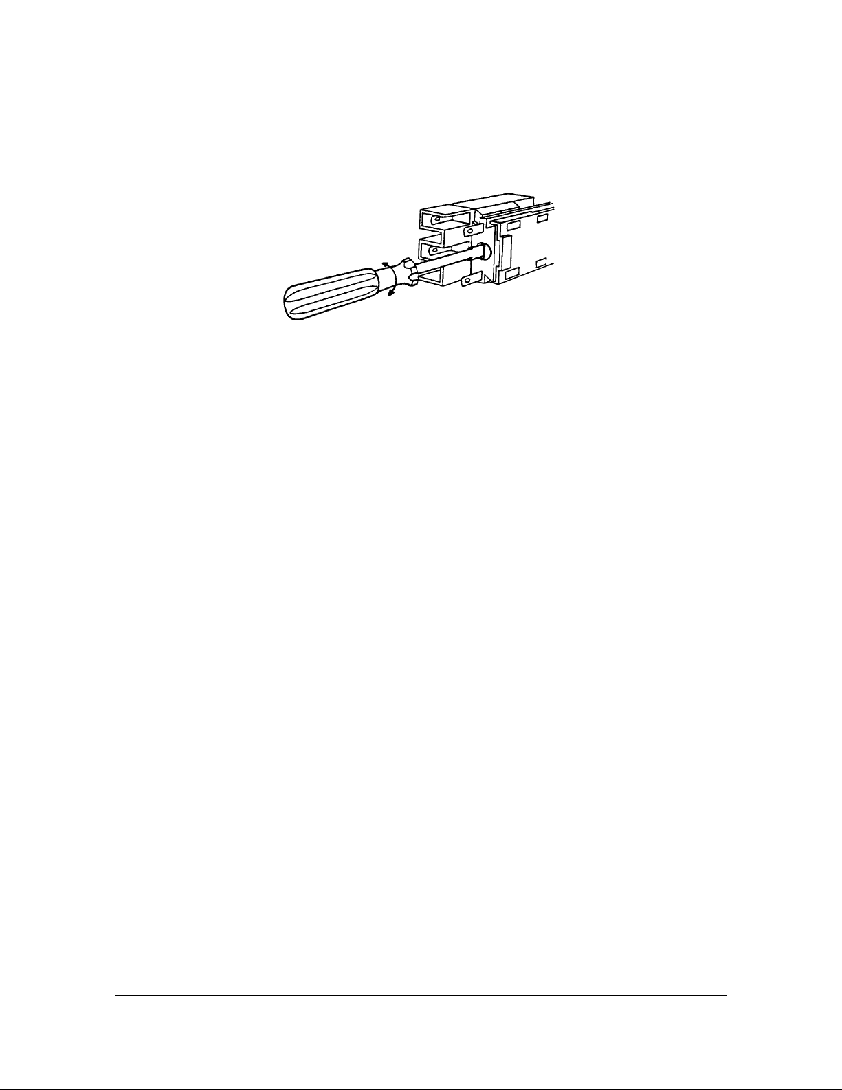
6.5. PUSH-BUTTON ASSEMBLY
Before removing the push button or the lockable Override/Automatic switch from the front panel turn the
screw 1/4 to the left, Figure 6.50. This will release the contact element.
Figure 6.50 Securing and removal of the contact element.
6.6. FUSES
The following fuses are printed on circuit board PR-7130:
Fuse F1: Microfuse IEC 127-3/1 DC Power (24 VDC) main fuse. Protects UL 198G 1A, fast
divert electronics againts wrong voltages especially from external DC supply.
Fuse F2: 5 x 20 mm fuse
IEC 60127, 1A, fast
AC supply to solenoid valves. Protects cable and coil, if faults
appear.
Fuses F3, F4: Microfuse IEC 127-3/1, Fuses protect switch of divert valve position UL 198G 63 mA,
fast feedback. Any external voltage connected to these circuits
causes fuse blow.
INSTRUCTION MANUAL FOR DD-01 DOCUMENT/REVISION: IMD 1/5
Effective: June 20, 2005
Page 26
25
7. DIVERT CONTROL LOGIC
A logical description of the system is provided as a complement to the previous information about the electronics.
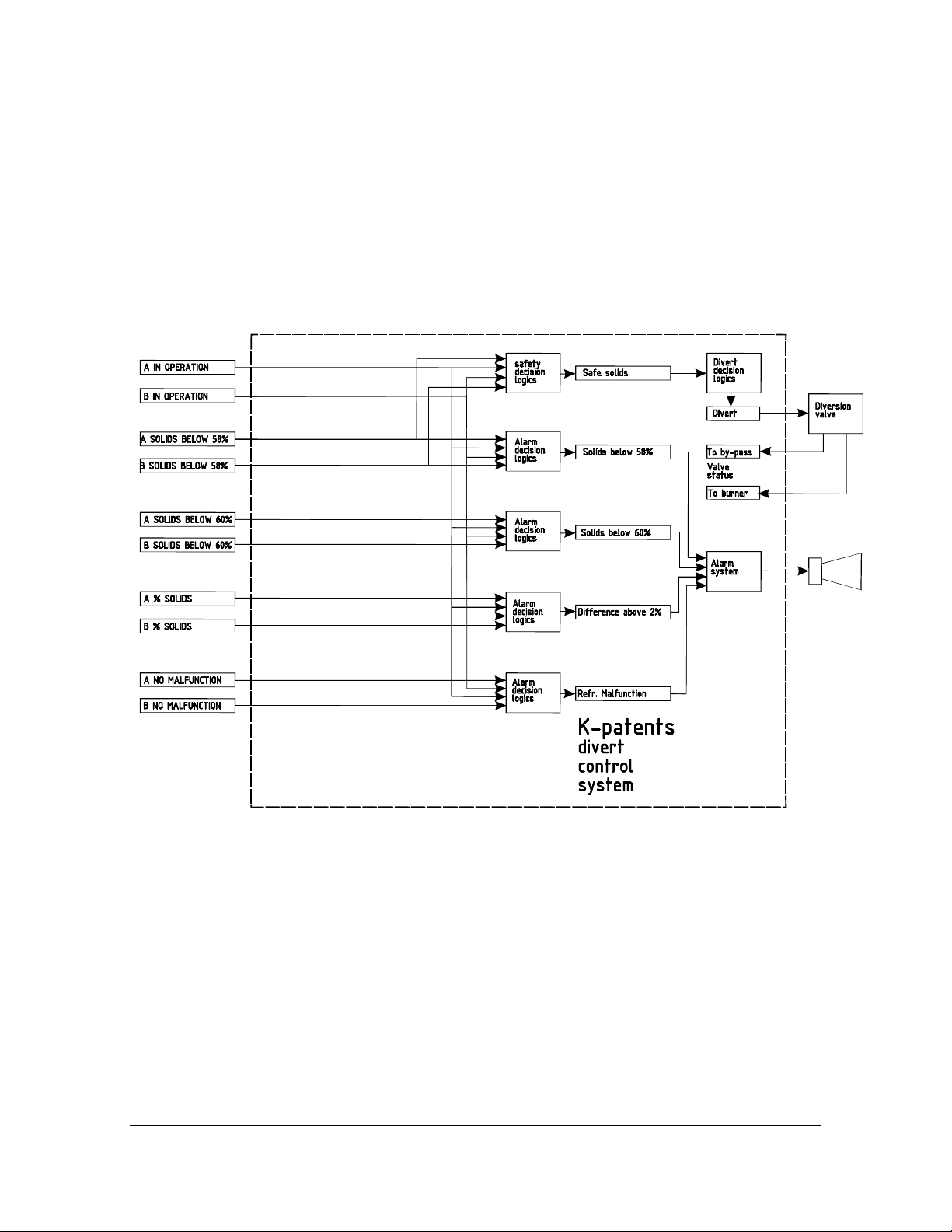
7.1. BLOCK DIAGRAM
The block diagram Figure 7.10 shows the connections between the different logical subsystems.
Figure 7.10 Block diagram of the divert control system
INSTRUCTION MANUAL FOR DD-01 DOCUMENT/REVISION: IMD 1/5
Effective: June 20, 2005
Page 27
26
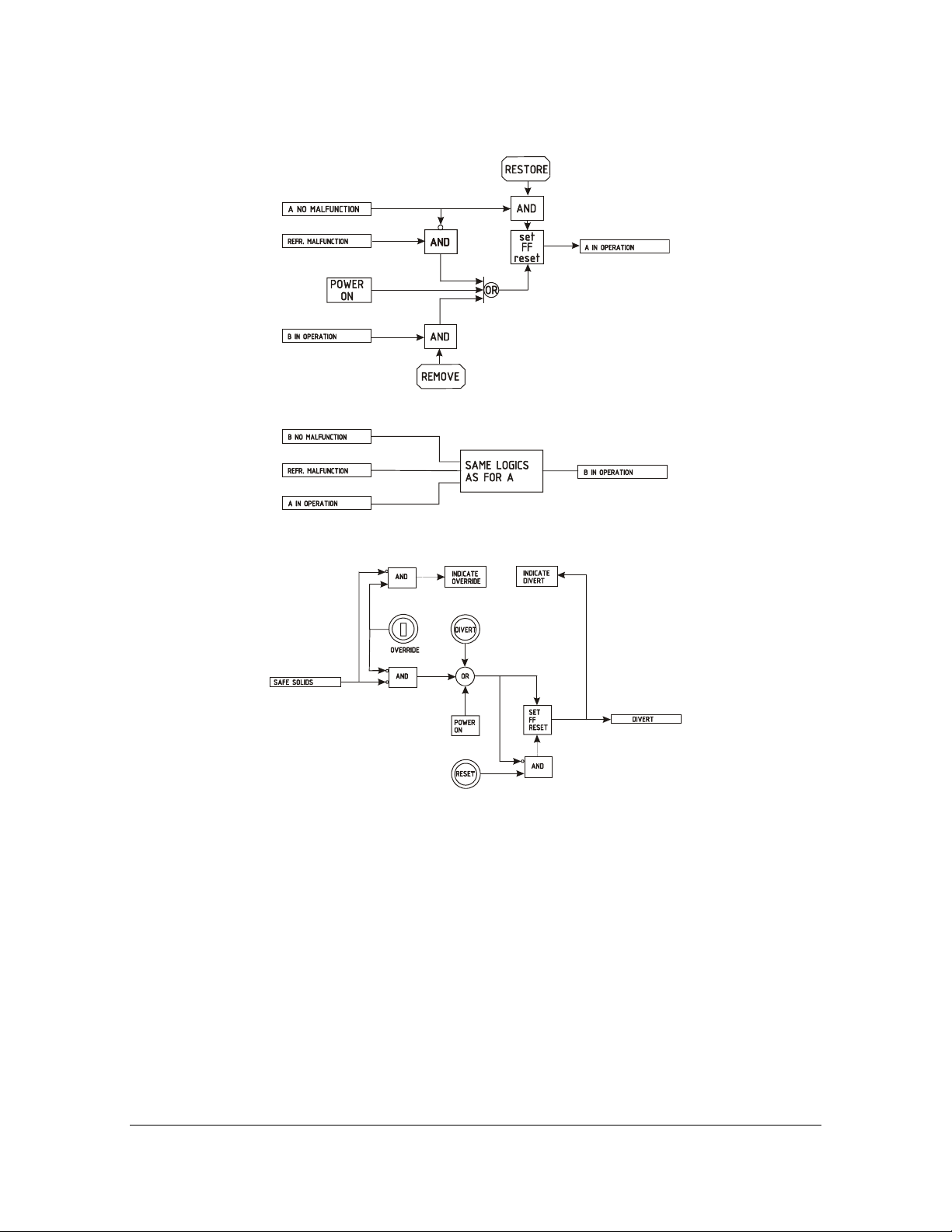
7.2. LOGICAL DIAGRAMS
Figure 7.20 The operation logics.
Figure 7.21 The divert decision logics.
INSTRUCTION MANUAL FOR DD-01 DOCUMENT/REVISION: IMD 1/5
Effective: June 20, 2005
Page 28

27
Figure 7.22 The alarm decision logics.
INSTRUCTION MANUAL FOR DD-01 DOCUMENT/REVISION: IMD 1/5
Effective: June 20, 2005
Page 29

28
Figure 7.23 The alarm system.
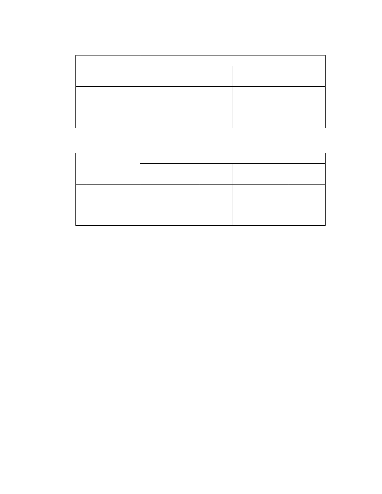
7.3. SAFETY DECISION LOGICS
The logical description of the Safety Decision Logics in Figure 7.10 is given by the following tables:
- Table 7.30 One - of - two
- Table 7.31 A master, B slave
- Table 7.32 Two - of - two
Note. NOT OPERATING includes the wash cycle.
See also Section 5.7.
A
<58
OPERATING
B <58 OPERATING
NOT OP
>58 OPERATING
NOT OP
Unsafe
Unsafe
Unsafe
Unsafe
NOT OP
Unsafe
Unsafe
Safe
Unsafe
>58
OPERATING
Unsafe
Safe
Safe
Safe
NOT OP
Unsafe
Unsafe
Safe
Unsafe
Table 7.30 One-of-two decision rule
INSTRUCTION MANUAL FOR DD-01 DOCUMENT/REVISION: IMD 1/5
Effective: June 20, 2005
Page 30
29
A
<58
OPERATING
<58 OPERATING
B
NOT OP
>58 OPERATING
NOT OP
Unsafe
Unsafe
Unsafe
Unsafe
NOT OP
Unsafe
Unsafe
Safe
Unsafe
>58
OPERATING
Safe
Safe
Safe
Safe
Table 7.31 A master, B slave
A
<58
OPERATING
B <58 OPERATING
NOT OP
>58 OPERATING
NOT OP
Unsafe
Unsafe
Safe
Unsafe
NOT OP
Unsafe
Unsafe
Safe
Unsafe
>58
OPERATING
Safe
Safe
Safe
Safe
NOT OP
Unsafe
Unsafe
Safe
Unsafe
NOT OP
Unsafe
Unsafe
Safe
Unsafe
Table 7.32 Two-of-two decision rule
INSTRUCTION MANUAL FOR DD-01 DOCUMENT/REVISION: IMD 1/5
Effective: June 20, 2005
Page 31

30
8. OPTIONAL CONFIGURATIONS
8.1. REMOTE DIVERT CONTROL UNIT
The remote divert control unit is an option of the digital divert control system DD-01, see Figure 8.20.
The remote divert control unit operates as a main unit, which means that the master divert unit is for indication
only. If the remote divert control unit is not in operation, the master divert unit in the field operates as a main
unit.
The remote control unit communicates with the master divert unit in the field through a modem. Connection
and wiring is made according to Figure 8.40.
For contact terminals see Figure 8.41. Contact terminals 24 and 25 are for communication OK signal.
8.2. EQUIPMENT
Figure 8.20 Complete remote divert control system.
INSTRUCTION MANUAL FOR DD-01 DOCUMENT/REVISION: IMD 1/5
Effective: June 20, 2005
Page 32
31
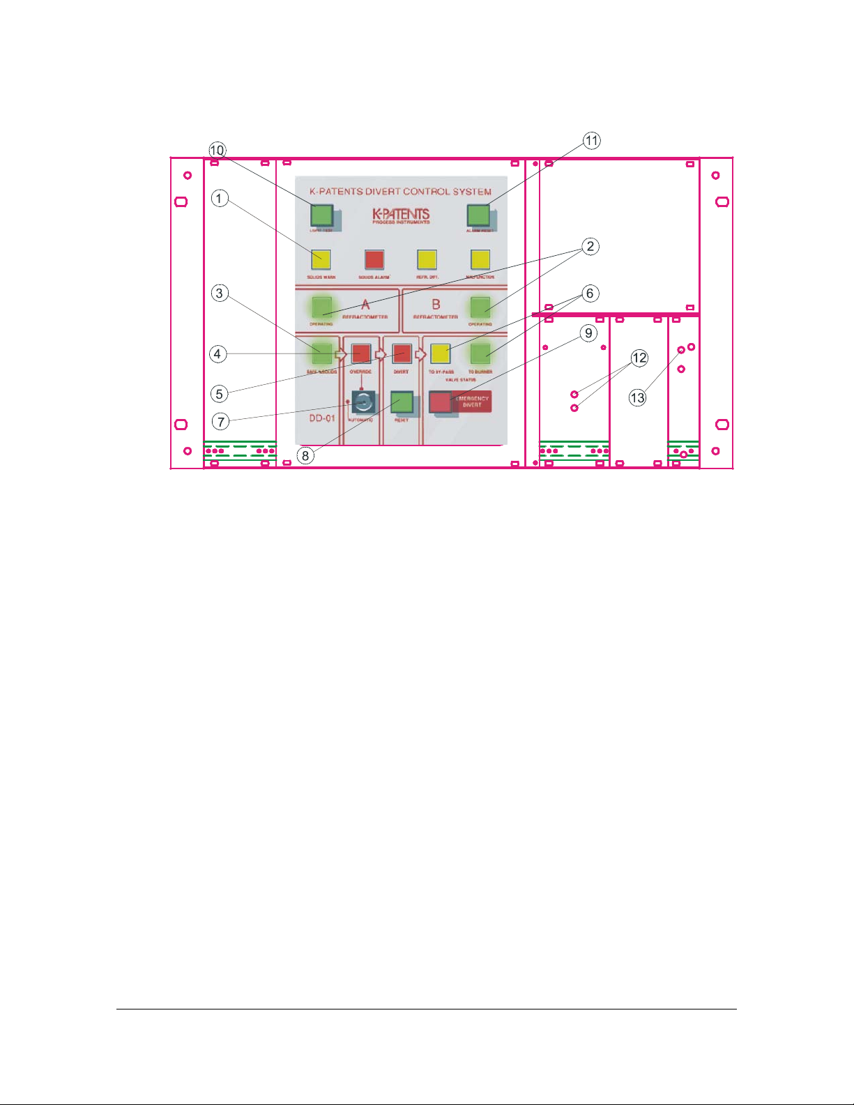
8.3. REMOTE DIVERT CONTROL UNIT IN THE CONTROL ROOM
Figure 8.30 Operator’s panel and functions of the remote divert control in the control room.
The remote divert control unit contains all information for the deviation decision. The operation is clearly
indicated with LED lights as follows:
1. A row of four alarms (indicating Black liquor SOLIDS WARNING (at 60%), Black liquor SOLIDS ALARM (below 58%), Refractometer reading more than 2% absolute difference, and Refractometer malfunction).
2. Each refractometer A and B has an
OPERATING green light, so the operator
knows when he can rely on the refractometer
measurement.
A refractometer will influence the divert decision only when the green OPERATING light is
on. A malfunctioning refractometer is automatically taken out of operation.
3. One green indicator light SAFE% SOLIDS,
based on the two refractometers and the divert
decision rules.
4. A red OVERRIDE warning light.
6. Two indicator lights for the divert valve
status. TO BY-PASS/TO BURNER from microswitches on the valve. For intermediate
valve positions both lights are off.
7. A lockable Override/Automatic switch.
8. One RESET push-button for the DIVERT
action. The DIVERT action always has to be
manually reset. If the override swithc is in
automatic position and SAFE% SOLIDS is off,
the DIVERT cannot be reset.
9. EMERGENCY DIVERT push-button.
10. A light test button switches all 11 lights on.
11. An alarm reset button resets the alarm
lights.
12. Communication to MASTER DIVERT ok,
indication light blinking.
5. One red DIVERT light that will be switched
on when the SAFE% SOLIDS goes off, providing OVERRIDE is off. The DIVERT light
indicates divert status of the divert relay.
INSTRUCTION MANUAL FOR DD-01 DOCUMENT/REVISION: IMD 1/5
Effective: June 20, 2005
13. Power supply ok, indication light on.
Note when remote divert in use, master divert unit in the field is for indication only!
Page 33

32
8.4. WIRING AND MOUNTING
For wiring of the complete system, see Figure 8.40, which also specifies the cables and connections.
Figure 8.40 Digital Divert Control System with Remote Divert Control Unit Wiring.
INSTRUCTION MANUAL FOR DD-01 DOCUMENT/REVISION: IMD 1/5
Effective: June 20, 2005
Page 34

33
Figure 8.41 Remote Divert Control Unit terminals.
Figure 8.42 Digital Divert Control System: Remote Divert Control Unit mounting.
INSTRUCTION MANUAL FOR DD-01 DOCUMENT/REVISION: IMD 1/5
Effective: June 20, 2005
Page 35

34
8.5. SERIAL OUTPUT
Each Indicating transmitter has a serial output not used by the Divert Control unit. This serial output is selectable RS-232/RS-485 (see PR-01-S Manual) and contains concentration, temperature and error data. It contains
also information whether the refractometer is in divert operation or not.
Possible uses of the Serial output: To communicate with a computer substituting the Divert Control unit.
8.6. CURRENT OUTPUT SIGNAL
Each Indicating transmitter provides a 4-20 mA output concentration signal not used by the Divert system. To
calibrate this signal for suitable %Solids range, press Calibrate/Output signal/Current output, see PR-01-S
Manual.
8.7. EXTERNAL DC POWER SUPPLY
The Divert Control unit may be connected to a DC power supply as a back-up. At AC power failure the refractometers will black-out, but the Divert Control unit will still work. In this case the DIVERT signal can be prevented by turning the key to OVERRIDE. Terminals are 15 (+24VDC) and 16 (ground).
The power requirement is 24 VDC, 500 mA.
8.8. DIVERT CONTROL UNIT CARD IN THE REMOTE UNIT
In the remote unit the divert control card the third dip switch SW3 must be in the ON position (“up”).
See Figure 3.13 and Sections 5.2. and 5.7.
INSTRUCTION MANUAL FOR DD-01 DOCUMENT/REVISION: IMD 1/5
Effective: June 20, 2005
Page 36

35
9. DIVERT CONTROL UNIT PARTS LISTS
9.1. DIVERT CONTROL UNIT AND OPTIONAL REMOTE DIVERT CONTROL UNIT
ltem Pcs. Part No. Description Item Pcs. Part No. Description
1 1 Enclosure 6.1 2 PR-6551 Switch unit, green
1.1 7 Conduit hubs 1/2”
NPT-Type ST-1 (US)
2.
3.1
3.2
3.3
1
1
1
1
PR-7310 Divert Control Unit
Card
Modem transformer
Modem card
Modem cable
4 1 PR-7028 Ribbon cable
5 1 PR-7311 LED Display card
6.2 1 PR-6551 Switch unit, red for Emergency divert
6.3
6.4
7.
1
1
1
PR-6551
PR-6552
PR-6501
Switch unit, green for Emergency divert reset
Lock unit for Automatic/Override divert operation
Divert Fuse set: 9 fuses (3 x
Microfuse 1A, fast IEC 1273/1, UL 198G; 3 x 5x20mm
Fuse 1A, fast; 3 x Microfuse
63 mA, fast IEC 127-3/1, UL
198G)
INSTRUCTION MANUAL FOR DD-01 DOCUMENT/REVISION: IMD 1/5
Effective: June 20, 2005
Page 37

36
9.2. REMOTE DIVERT CONTROL UNIT
ltem Pcs. Part No. Description
6.1 2 PR-6551 Switch unit, green
6.2 1 PR-6551 Switch unit, red for Emergency divert
6.3 1 PR-6551 Switch unit, green for Emergency divert
6.4 1 PR-6552 Lock unit for Automatic/Override divert
8.1 1 PR-7310-RACK
8.2 RACK-modem
8.3 1 RACK Power 24V
reset
operation
INSTRUCTION MANUAL FOR DD-01 DOCUMENT/REVISION: IMD 1/5
Effective: June 20, 2005
 Loading...