

Quality Fireplaces for Life
INSTALLATION MANUAL
INSTALLER: LEAVE THIS MANUAL WITH THE APPLIANCE
D
O
N
D
I
O
A
R
D
T
S
C
Contact local building or fire officials about restrictions
and installation inspection requirements in your area.
Please read this entire manual before installation and use of this wood pellet fuel burning room heater.
Failure to follow these instructions could result in property damage, bodily injury or even death.
This stove must only be installed with factory approved and tested components. Use of components not tested and approved for
use with this stove or using another manufacturer’s components my result in a fire or safety hazard and voids all warranty.
July-2008
WLD-P-Rev-01

TABLE OF CONTENTS
SAFETY INFORMATION
VENT SYSTEM REQUIREMENTS 2
APPROVED VENTING COMPONENTS 3
MOBILE HOME INSTALLATIONS 3
SPECIFICATIONS 3
CLEARANCES 4
VENTING ILLUSTRATIONS 5
VENTING TERMINATION REQUIREMENTS 6
MINIMUM EXHAUST TERMINATION CLEARANCES 7
COMBUSTION AIR REQUIREMENTS 8
SEPARATE EXHAUST & COMBUSTION VENT PIPE TERMINATIONS 8
#WLD-WPT WALL PASS THRU INSTALLATION INSTRUCTIONS 8-9
ELECTRICAL COMPONENTS 10
THERMOSTAT INSTALLATION (optional) 11
WARRANTY 12
1
PAGE 1

SAFETY INFORMATION
This wood pellet stove, Woodland model #WLD-P, has been tested and certified by OMNI-Test Laboratories, Inc., Portland, Oregon, to comply with ASTM E1509-04, ‘Tested & Certified Room Heater, Pellet Fuel-Burning Type’. Also for use in Mobile
Homes. Installation must comform with applicable requirements of NFPA 211, and applicable building & mechanical codes.
• DO NOT CONNECT THIS UNIT TO A CHIMNEY FLUE SERVING ANOTHER APPLIANCE
• DO NOT INSTALL A FLUE DAMPER IN THE EXHAUST VENTING SYSTEM OF THIS UNIT.
• This stove’s exhaust system operates under negative pressure in the combustion chamber and positive pressure
in the chimney. It is imperative that the vent system used on this stove is properly installed and airtight.
• Smoke detectors installed in the same room as this stove may activate if smoke from the firebox is allowed to
enter the room or if the ash drawer is emptied while still smoking.
• This stove is approved for U.S. conventional & mobile home installations.
WARNING:
THE STRUCTURAL INTEGRITY OF THE MANUFACTURED HOME FLOOR, WALL, AND CEILING/
ROOF MUST BE MAINTAINED.
DO NOT INSTALL IN A SLEEPING ROOM.
DO NOT BURN GARBAGE OR FLAMMABLE FLUIDS SUCH AS GASOLINE, NAPHTHA OR ENGINE OIL.
VENT SYSTEM REQUIREMENTS
• Type ‘L’ vent systems must be used. Follow vent manufacturer’s clearance requirements. Refer to local building codes, appliance and vent
system manufacturer’s instructions for precautions required when passing through a combustion wall or ceiling.
• This stove utilizes 3” exhaust pipe. Use appropriate adaptor for proper connection to exhaust collar.
• Outside air is REQUIRED for proper operation of this stove. This stove utilizes a 2” O.D. intake (2” PVC pipe is permitted. Use appropri-
ate adaptor for proper connection to intake collar.
• An optional wall-thimble / outside air assembly, Part #WLD-WPT, is available. (Not for use with Selkirk-Metalbestos Direct-Temp vent
system).
• All joints for connector pipe shall be required to be fastened with at least (3) screws. If vented horizontally, joints shall be made air tight
using high temp sealant, RTV, or metal tape at each joint.
• A clean out ‘tee’ must be installed directly to the stove and at the bottom of each vertical run of the vent (exhaust) system. The tees will
provide easy access for cleaning the vent system. Single or double clean-out tee may be used.
• THE EXHAUST SYSTEM MUST BE INSTALLED SO THE ENTIRE SYSTEM MAY BE CLEANED WITHOUT DISASSEMBLY.
CAUTION:
DO NOT CONNECT TO ANY AIR DISTRIBUTION DUCT OR SYSTEM.
• It is recommended that the vent system be installed with a minimum vertical rise of 3 ft. (914 mm) above the stove exhaust connection.
- Failure to provide adequate natural draft (vertical rise) may result in smoke being released into the house if electricity to the stove is interrupted while burning or smoldering wood pellets remain in the burn pot.
• Increasing the vertical exhaust system is recommended when: Using more than (1) elbow or tee.
Horizontal run is over 3 ft. (914 mm).
• Horizontal terminations: The exhaust pipe must be terminated by a listed end cap or an ‘L’ vent elbow (45 or 90 degree). End caps or el-
bows must vent exhaust gases away from building.
PAGE 2
APPROVED VENTING COMPONENTS
• Kozy Heat Wall Pass-Thru (#WLD-WPT).
• Simpson Dura-Vent type ‘L’ Vent System.
• Selkirk-Metalbestos Direct-Temp direct vent system.
• Alternate brands may be used provided they are approved by a certified testing agency as a Type ‘L’ system.
IMPORTANT: Installation must comply with the vent pipe manufacturer’s installation instructions, the requirements / restrictions as
outlined in this installation manual and local building codes.
MOBILE HOME INSTALLATIONS
This stove may be installed in a permanently located, manufactured or mobile home where not prohibited by local codes.
The following requirements must be followed:
• Outside combustion air for all installation types is required for proper operation of this stove.
WARNING:
THE STRUCTURAL INTEGRITY OF THE MANUFACTURED HOME FLOOR, WALL, AND CEILING/ROOF MUST BE MAINTAINED.
DO NOT INSTALL IN A SLEEPING ROOM.
• Permanently bolt stove to floor. Floor protection requirements must be followed.
• Electrically ground stove and pedestal to metal chassis of the home with number 18 gauge or higher copper wire.
• Maintain an effective vapor barrier at location where ’L’ vent exits structure.
• ‘L’ Vent must be used for exhaust venting. (Single wall venting not allowed). Follow ‘L’ Vent manufacturer’s installation directions and
observe all listed clearances to combustibles.
• Check local codes for additional requirements / restrictions concerning mobile home installations.
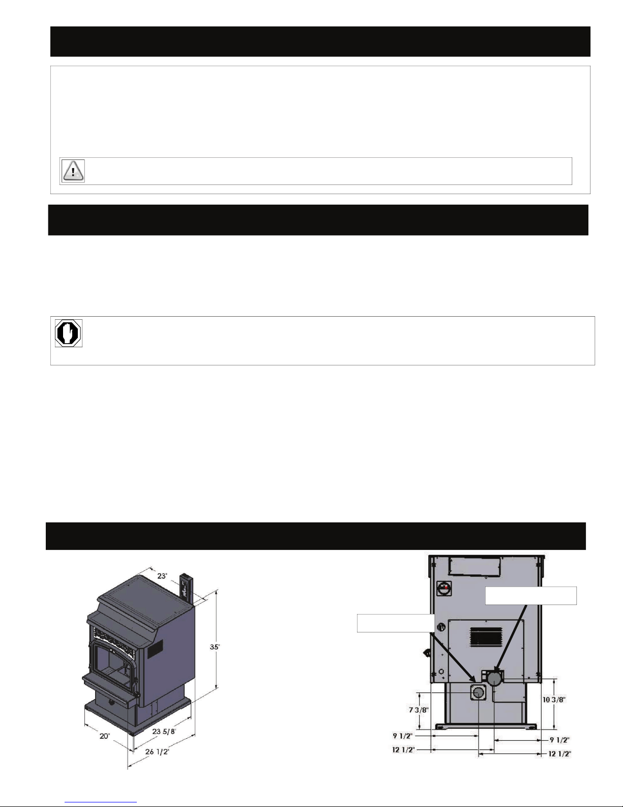
SPECIFICATIONS
EXHAUST COLLAR
INTAKE COLLAR
PAGE 3
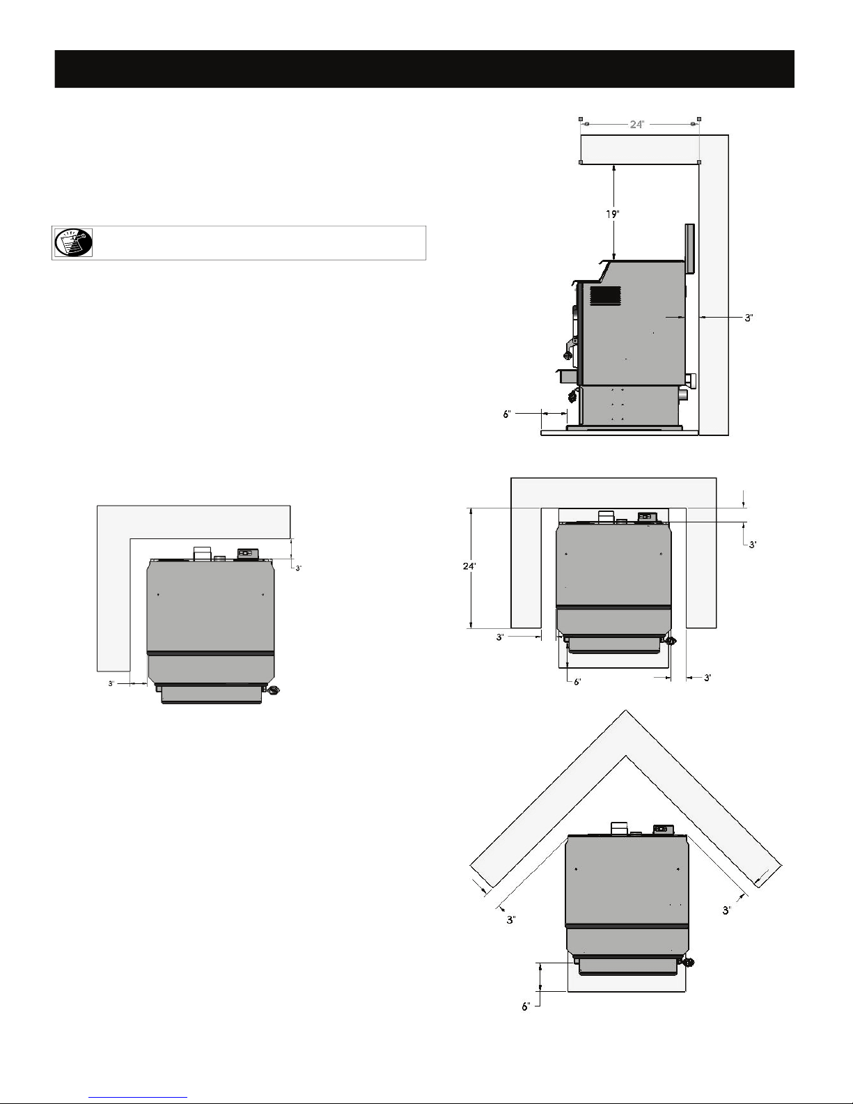
CLEARANCES
The installation of this freestanding stove must meet the following minimum requirements
Sides of stove………………………………………………...3” (76 mm)
Back of stove………………………………………….……..3” (76 mm)
Corner of stove……………………………………….……...3” (76 mm)
From Dura-Vent Pellet vent pipe…………………………….1” (25 mm)
From Selkirk-Metalbestos vent pipe……………………....….1” (25mm)
NOTE: Follow vent manufacturer’s clearance requirements.
Floor Protection;
Front (from faceplate)……………………………..…………6” (152 mm)
From sides of door opening………………………………..….3” (76 mm)
From back of stove:
»Must extend to wall if vent system horizontally exits through wall.
»Must extend under ‘tee’ if vertical pipe is located in interior of house.
Alcove Installations:
Minimum height from top of stove………………………....19” (483 mm)
From alcove sides / back…………………………….………..3” (76 mm)
Maximum alcove depth…………………………..………...24” (610 mm)
Alcove Installation
Alcove Installation
PAGE 4
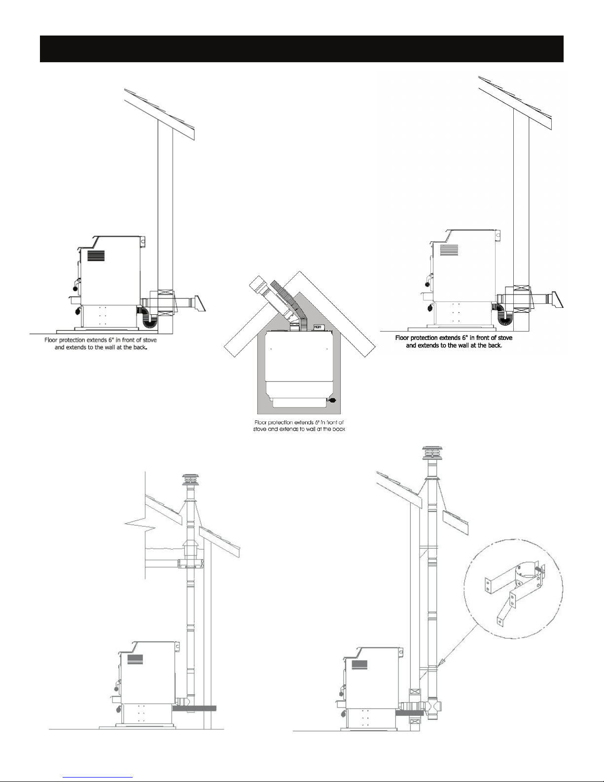
VENTING ILLUSTRATIONS
Horizontal Termination #2 Horizontal Termination #1
Typical Corner Installation
Vertical Termination #1 Vertical Termination #2
(Not recommended for cold
climate installation).
PAGE 5

VENTING TERMINATION REQUIREMENTS
MAXIMUM HORIZONTAL RUN: 9 ft (2.74 m)
MAXIMUM VERTICAL RUN: 36 ft. (10.97 m)
Items to consider when determining the best location for vent termination cap:
Distance from air inlets
being used and local building codes.
Prevailing winds - When terminating where prevailing winds may blow against the termination cap, sporadic operation of this stove may
result which may include excessive smoking inside firebox.
Location of adjacent structures - Installation must comply with the requirements in this installation manual, the requirements of the vent
system being used and local building codes.
Local code requirements - Check local building codes for additional requirements and / or restrictions concerning installation of a wood
pellet burning stove.
Exhaust must terminate above combustion air inlet when using separate exhaust / combustion air vent pipes.
Do not terminate vent in any enclosed or semi-enclosed area (i.e. garage, attic, crawl space, etc.) or any area which would build up a concentration of fumes.
Vent surface can become hot enough to cause burns if touched by children. Use non-combustible guards or shields if necessary.
Combustion air must be connected to an outside source and not drawn from the indoor living environment, garage, attics, crawl spaces and the
like.
- Installation must comply with the requirements in this installation manual, the requirements of the vent system
PAGE 6
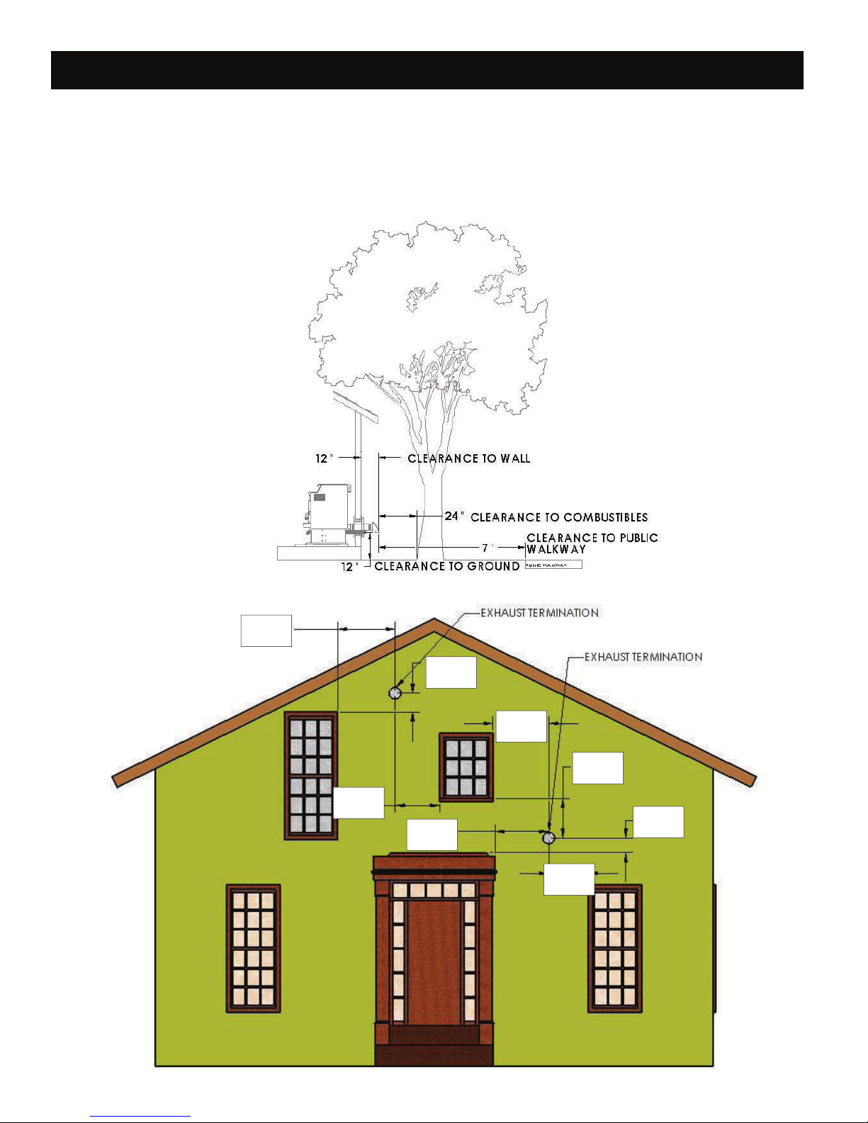
MINIMUM EXHAUST TERMINATION CLEARANCES
1. Above ground level: 12” (305 mm)
2. Above ground level when located adjacent to public walkways: 7’ (2.1 m)
3. From wall penetration point: 12” (305 mm)
4. From any adjacent combustibles - i.e.: fences, adjacent buildings, protruding parts of the structure, roof eaves or overhangs, plants, shrubs:
24” (610 mm)
5. Below a door, window, cavity, or air vent: 9” (229 mm)
6. Horizontally from a door, window, cavity, or air vent: 9” (229 mm)
9”
(229 mm)
9”
(229 mm)
(229 mm)
9”
(229 mm)
9”
9”
(229 mm)
9”
(229 mm)
9”
(229 mm)
9”
(229 mm)
PAGE 7
COMBUSTION AIR REQUIREMENTS
This stove requires the use of outside air for combustion. A 2” (51 mm) diameter aluminum flex pipe 4 ft. (1.2 m) long is included with
this stove to connect to the 2” (51 mm) intake collar located at the back of stove.
WARNING: THE COMBUSTION AIR PIPE MUST BE PROPERLY
CONNECTED TO THE OUTDOORS FOR PROPER PERFORMANCE.
• Do not crush or over bend flex pipe which may create air flow blockage, resulting in poor operation of stove.
• Attach 2” (51 mm) aluminum flex pipe ( 2” PVC pipe also permitted) over intake collar on stove. Seal the connection.
SEPARATE EXHAUST & COMBUSTION VENT PIPE TERMINATIONS
• Use of a hood for wind and weather protection is recommended.
• An open mesh screen, no smaller than 1/4” x 1/4” (6 mm x 6 mm) should be placed over outside air pipe opening to prevent birds, rodents
or insects from entering.
• Locate the outside air pipe termination (and hood) above maximum snow depth.
• Terminate the shortest distance possible. If length of combustion air pipe is over 10 ft. (3.05 m), we suggest increasing to a 3” (76 mm) di-
ameter pipe.
• The outside air must terminate below the exhaust outlet.
#WLD-WPT WALL PASS THRU INSTALLATION INSTRUCTIONS
This optional outside air wall pass-thru has been designed for use with ‘direct thru the wall’ horizontal terminations using the Simpson DuraVent ‘L’ vent system and will provide the outside air required for proper installation and operation of the Woodland Pellet Stove.
MINIMUM WALL THICKNESS: 5-1/2” (140 mm)
MAXIMUM WALL THICKNESS: 9-1/2 (241 mm)
• If possible, locate vent system between studs.
• Avoid electrical wires running through wall.
• It may be necessary to adjust the stove position slightly to avoid
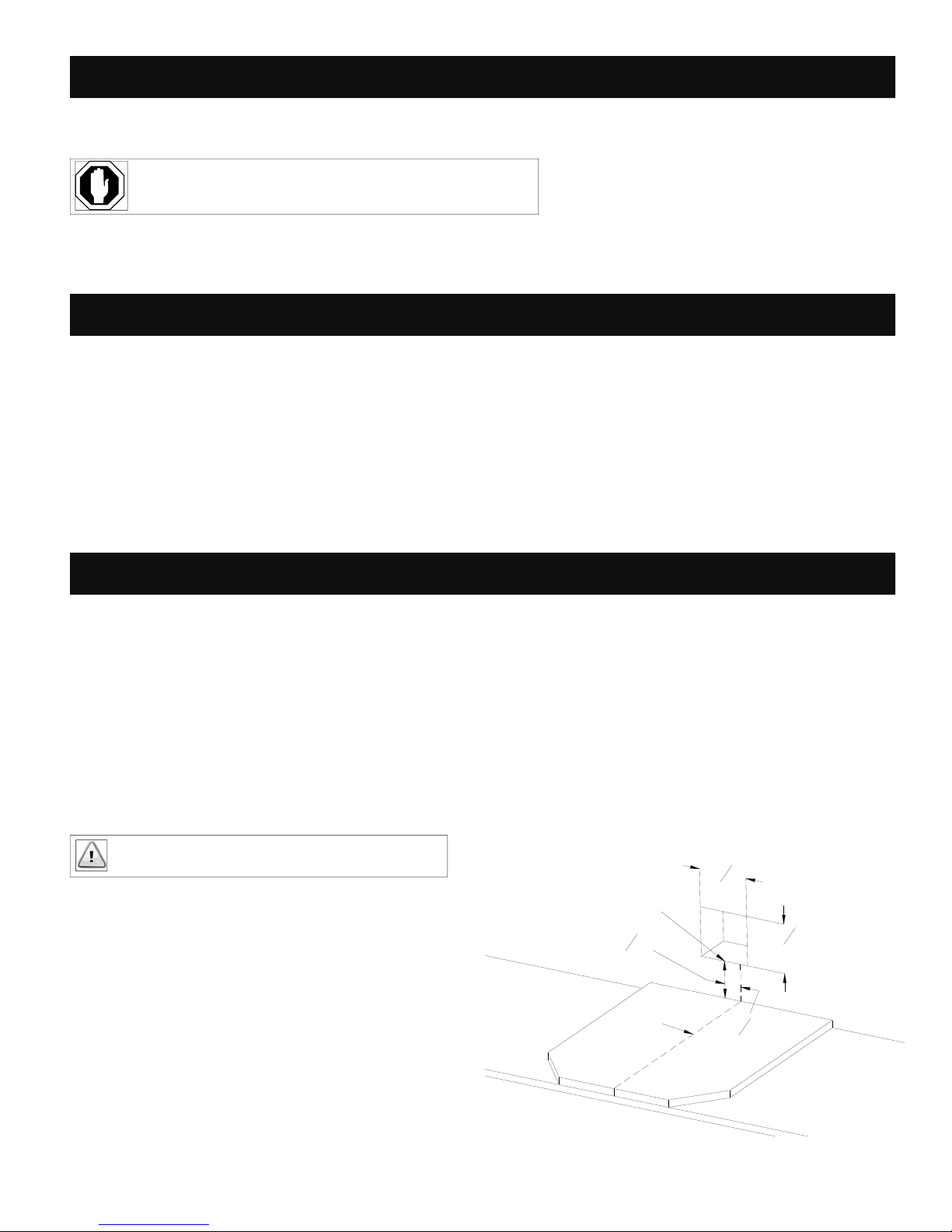
IMPORTANT: Height of floor protector must be considered
when determining wall pass-thru location.
1. Determine the center point of wall end of hearth pad.
2. Offset this measurement 2-1/2” (64 mm) to the left and then 61/2” (165 mm) up. This represents the bottom center of the 71/4” x 7-1/4” (184 mm x 184 mm) square opening required for
the wall pass-thru.
3. Mark and cut the 7-1/4” x 7-1/4” (184 mm x 184 mm) square
opening through the building exterior.
4. If necessary, install wood backer strips for support of wall passthru when mounted.
BOTTOM CENTER OF OPENING
1
6
"
2
165mm
CENTER OF STOVE
184mm
1
"
7
4
1
2
2
64mm
1
7
"
4
184mm
"
PAGE 8

#WLD-WPT WALL PASS THRU INSTALLATION INSTRUCTIONS (cont.)
5. Center and secure the interior wall pass-thru to the square opening.
NOTE: Orientation of 2” (51 mm) collar must be either on right side as shown throughout these instructions or in the down
position to properly connect the 2” (51 mm) flex pipe.
Exterior wall pass-thru section
Interior wall pass-thru section
6. From outside of building: Slide the exterior wall pass-thru section into the interior section.
The overlap should be no less than 1/2” (13 mm). Do not secure at this time.
7. Apply sealant / silicone around 2” (51 mm) combustion collar on stove. Slide the 2” (51 mm)
flex pipe onto collar.
IMPORTANT: The outermost end of termination cap must be a minimum of
12” (305 mm) from the exterior wall once installed. Please factor this in when
determining vent pipe length.
8. From the outside of building: Slide the first section of vent pipe through the wall pass-thru to
the interior of building.
9. Apply sealant / silicone around the exhaust collar on stove. Positioning stove as close to
back wall as possible, approximately 5” (127 mm) away, slide collar onto vent pipe. Secure
with screws.
Minimum 12” (305 mm)
Approx. 5” (127 mm)
from back wall
Connect outside
air pipe
10. Cut 2” (51 mm) flex pipe desired length. Apply sealant / silicone around collar, slide flex pipe onto collar. Secure with screws if desired.
11. From the outside of building: Secure wall pass-thru to exterior wall, keeping in mind the collars on wall pass-thru must overlap at least
1/2” (51 mm) and the plate must be secured to exterior wall. If too long, the collar may be cut down to allow proper installation to the
exterior wall while still maintaining a minimum 1/2” (51 mm) overlap.
12. After exterior wall pass-thru section is secured, apply exterior sealant around flange of exterior section and exterior wall.
13. Connect remaining vent pipe sections together and attach termination cap.
PAGE 9

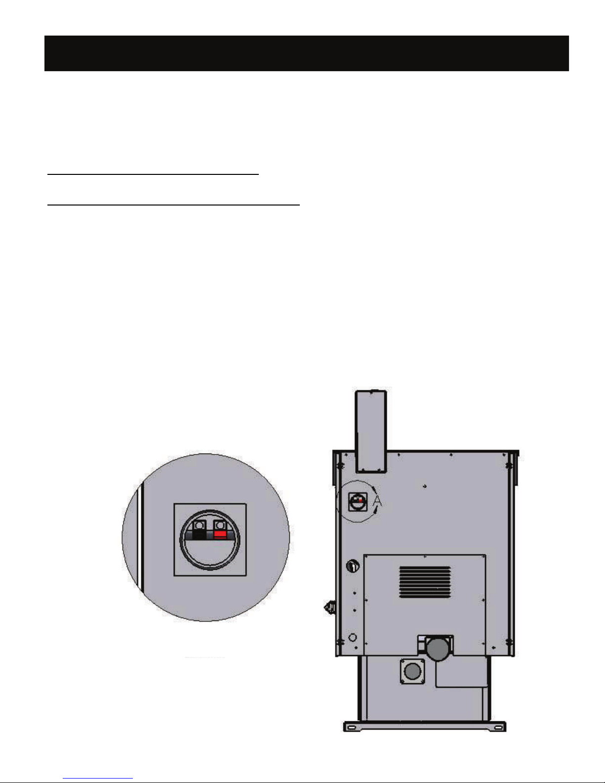
ELECTRICAL COMPONENTS
This stove includes a combustion fan and room fan with a 3-prong (grounding ) plug. The fans must be plugged into a properly grounded 3-prong
outlet. The current required is approx. 3 amps (5 amps when ignitor is in operation).
Run power cord to nearest outlet. Do not allow electrical cord to come in contact with any hot or sharp surfaces on stove.
When this stove is installed in a mobile home, it must be electrically grounded to the steel chassis of the home and bolted to the floor, according
to building code requirements.
CONTROL BOARD
HOT
BLACK
120 VOLT AC
COMMON
WHITE
PIN OUT ON
MOLEX CONNECTOR
WIRE SIDE
1 2 3 4 5 6
7 8 9 1 0 11 12
WIRE COLORS
1 ORANGE
2 GRAY
3 PINK
4 BLUE
5 YELLOW
6 RED
7 ORANGE
8 GRAY
9 BROWN
10 BROWN
11 WHITE
12 BLACK
WHITE
AUGER MOTOR
WHITE
TERMINAL BLOCK
COMMON
WHITE
IGNITER
CONVECTION FAN
SAFETY INTERLOCK
SWITCH
YELLOW
RED
PINKWHITE
YELLOW
COMBUSTION
FAN
BLUE
THERMOSTAT WIRE
PINK
SAFETY INTERLOCK SWITCH IS LOCATED ON HOPPER LEDGE UNDER LID
BROWN
BROWN
GRAY
GRAY
ORANGE
ORANGE
PROOF OF FIRE
SWITCH N/O
VACUUM
SWITCH N/O
HIGH LIMIT
SWITCH N/C
PAGE 10
THERMOSTAT INSTALLATION (optional)
An optional thermostat is available for use on this stove. A thermostat will maintain a constant level of heat, resulting in optimal fuel consumption,
ultimately lowering heat costs.
This stove is pre-wired and capable of operating on a thermostat. A feature has been built into the circuit control board which delays the time between each heat setting to allowing the stove to react at each subsequent level. It will take approximately 2-5 minutes for the control box to operate
at the full capacity for the heat level chosen.
As the room temperature falls below the thermostat temperature setting, the stove will operate at one of the (5) settings previously chosen.
The ON/OFF LED light will be constant during this time.
When the room temperature reaches the thermostat set temperature, the stove will automatically operate at the lowest setting (#1).
The ON/OFF LED light will blink until the thermostat calls for heat.
Install thermostat panel in neutral location to ensure accurate room temperature readings.
THERMOSTAT HOOK-UP
Install thermostat by connecting the wires on thermostat to external wire terminal block at back of stove. The external terminal has been pre-wired
to the thermostat wire hook-up on the back of the control board.
THERMOSTAT SETTINGS:
1. Slide switch on control circuit board to ‘T-stat” setting after stove is in full operating mode.
2. Set thermostat to desired setting..
3. Set heat level on control board high enough to raise room temperature above thermostat setting.
4. We recommend restarting stove in Manual Mode.
PAGE 11
6 YEAR LIMITED WARRANTY
This 6 Year Limited Warranty, subject to the conditions, exclusions and requirements listed below, will not become effective until the warranty registration form
has
been completed and mailed to Hussong Manufacturing Co., Inc., P.O. Box 577, Lakefield, MN 56150. This registration form must be received
within 30 days of installation. Failure to do so may result in delayed warranty coverage. Hussong Manufacturing Co., Inc. warranties to the original
purchaser of the Kozy Heat Model #WLD-P Woodland Pellet Stove, that it is free of defects in materials and workmanship at the time of manufacture.
1 YEAR: This stove is warranted for the first year form the day of purchase against defects and workmanship on all steel components. Hussong
Manufacturing Co., Inc. shall, at Hussong Manufacturing Co., Inc.’s expense, including reasonable labor costs, repair or replace any defective component, if a factory pre-authorization is give for the repair.
2 YEARS: Electrical Components: This stoves electrical components are warranted against defects and failures for 2 years from date of purchase.
Hussong Manufacturing Co., Inc., will at its discretion, repair or replace any such defect of electrical components, including optional components. Hussong Manufacturing Co., Inc. shall not be responsible for any installation, labor, transportation or other indirect costs after the first year from date of
purchase.
YEARS 2-6: From the first day of the second year through the 6th year, Hussong Manufacturing Co., Inc. shall, at it’s discretion, repair or replace any
defective component, if a factory pre-authorization is given for the repair or replacement. Hussong Manufacturing Co., Inc. shall not be responsible for
any installation, labor, transportation or other indirect costs.
LIMITATION OF LIABILITY
To make a claim under this warranty, the purchaser must first contact the dealer/installer from whom this stove was purchased.
This limited warranty will be void if this stove is not installed according to the installation instructions provided. This limited warranty is also void if
the stove is not operated and maintained according to the Operating & Maintenance manual provided. Use of unauthorized components will make this
warranty null and void.
This warranty is limited to defects in material and workmanship. It does not apply to any product that has been subject to negligence, misapplication,
improper installation. Products made by other manufacturers are NOT covered by this Limited Warranty, regardless of whether they were purchased
with the stove or added later.
No person is authorized to extend the time of this warranty or to accept on Hussong Manufacturing Co., Inc.’s behalf any additional obligation of liability connected with the stove.
It is expressly agreed and understood that this warranty is Hussong Manufacturing Co., Inc.’s sole obligation and purchaser’s exclusive remedy for
defective stove equipment. Hussong Manufacturing Co., Inc. shall not be liable for any consequential, incidental or contingent damages whatsoever.
The forgoing warranty is exclusive and in lieu of all other expressed warranties. Hussong Manufacturing Co., Inc. shall not be held to implied warranties or merchantability and fitness for a particular purpose. This warranty replaces all previous warranty policies.
Some states do not allow the exclusion or limitation of incidental or consequential damages or limitation on how long an implied warranty lasts, so the
above limitations or exclusions may not apply to you. This warranty gives you specific legal rights and you may also have other rights which vary
from state to state.
Hussong Manufacturing Co., Inc. reserves the right to make changes at any time, without notice, in design, material, specifications and prices. Hussong
Manufacturing Co., Inc. reserves the right to discontinue models and products.
WARRANTY CONDITIONS, EXCLUSIONS & REQUIREMENTS:
1. You are the original purchaser. This warranty is not transferable.
2. Installation, operation and maintenance must comply with the installation instructions and operating & maintenance manual provided with this
stove.
3. Glass is covered for one year from date of purchase.
4. Paint and glass gaskets are covered for 30 days from date of purchase.
5. Components, including the glass panel that are broken during shipping, careless handling of components, or defects resulting from improper installation, misuse of stove and components are not covered under this warranty.
6. This warranty does not cover any parts or components which have been exposed to or submerged under water.
7. Hussong Manufacturing Co., Inc. must be notified by the dealer this stove was purchased from or a service technician of the defect.
8. All previous warranty/service has been performed by a qualified service technician. (Copies of such service records may be required to claim warranty.
PAGE 12

 Loading...