

kozy heat windom 56101 Installation And Operation Manual
INSTALLATION AND OPERATION MANUAL
English and French Installation Manuals
Available Through Your Local Dealer or
Visit Our Website at www.kozyheat.com
DIRECT VENT FIREPLACE
INSTALLER: Leave this manual with the appliance.
CONSUMER: Retain this manual for future reference.
This applia nce may be installe d in an afte rmarket permanent ly located,
manufactured home (USA only) or mobile home, where not prohibited by local codes.
This appliance is only for use with the types of gas indicated on the rating plate. A
conversion kit is supplied with the appliance.
WARNING: If the information in these instructions is not followed exactly, a fire
or explosion may result causing property damage, personal injury or loss of life.
— Do not store or use gasoline or other flammable vapors and liquids in the vicinity
of this or any other appliance.
WHAT TO DO IF YOU SMELL GAS:
◙ Do not try to light any appliance.
◙ Do not touch any electrical switch; do not use any phone in your building.
◙ Immediately call gas supplier from a neighbors phone. Follow the gas supplier
instructions.
◙ If you cannot reach your gas supplier, call the fire department.
— Installation and service must be performed by a qualified installer, service
agency or the gas supplier.
WARNING
HOT GLASS WILL CAUSE BURNS.
DO NOT TOUCH GLASS UNTIL COOLED.
NEVER ALLOW CHILDREN TO TOUCH GLASS.
Report No. 216-S-02b-5
December-2011
WDM-R09
www.kozyheat.com
INTRODUCTION
Read this manual before installing or operating this appliance.
Please retain this owner‟s manual for future reference.
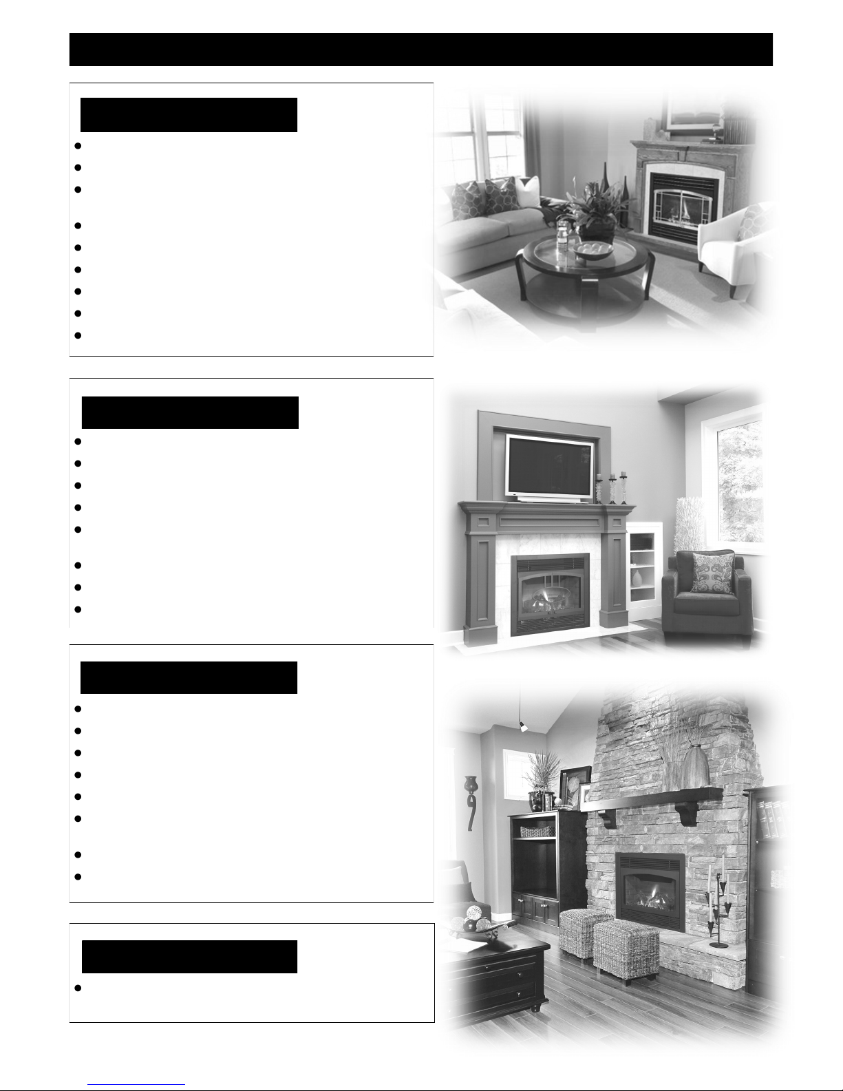
CONGRATULATIONS!
We welcome you as a new owner of a Kozy Heat gas fireplace. Kozy Heat products are
designed with superior components and materials and assembled by trained craftsmen who
take pride in their work. The burner and valve assembly are 100% test-fired and the complete
fireplace is thoroughly inspected before packaging to ensure that you receive a quality product.
Our commitment to quality and customer satisfaction have remained the same for over 30
years. We offer a complete line of gas and wood fireplaces, unique cabinets and stylish
accessories to compliment any décor. Adding a fireplace is one of the best ways to increase the
value of your home and we are proud to offer a network of dealers throughout the country to
help make your experience everything you imagine. We pride ourselves in being dedicated to
not only function and reliability, but customer safety as well. We offer our continual support
and guidance to help you achieve the maximum benefit and enjoyment from your Kozy Heat
gas fireplace.
Jim Hussong Dudley Hussong
President Board Chairman
Homeowner Reference Information
We recommend that you record the following information about your fireplace.
Model Name:______________________________ Date purchased/installed:_____________________________________
Serial Number:____________________________ Location on fireplace:________________________________________
Dealership purchased from:__________________ Dealer Phone:______________________________________________
Notes:_______________________________________________________________________________________________
____________________________________________________________________________________________________
____________________________________________________________________________________________________
1
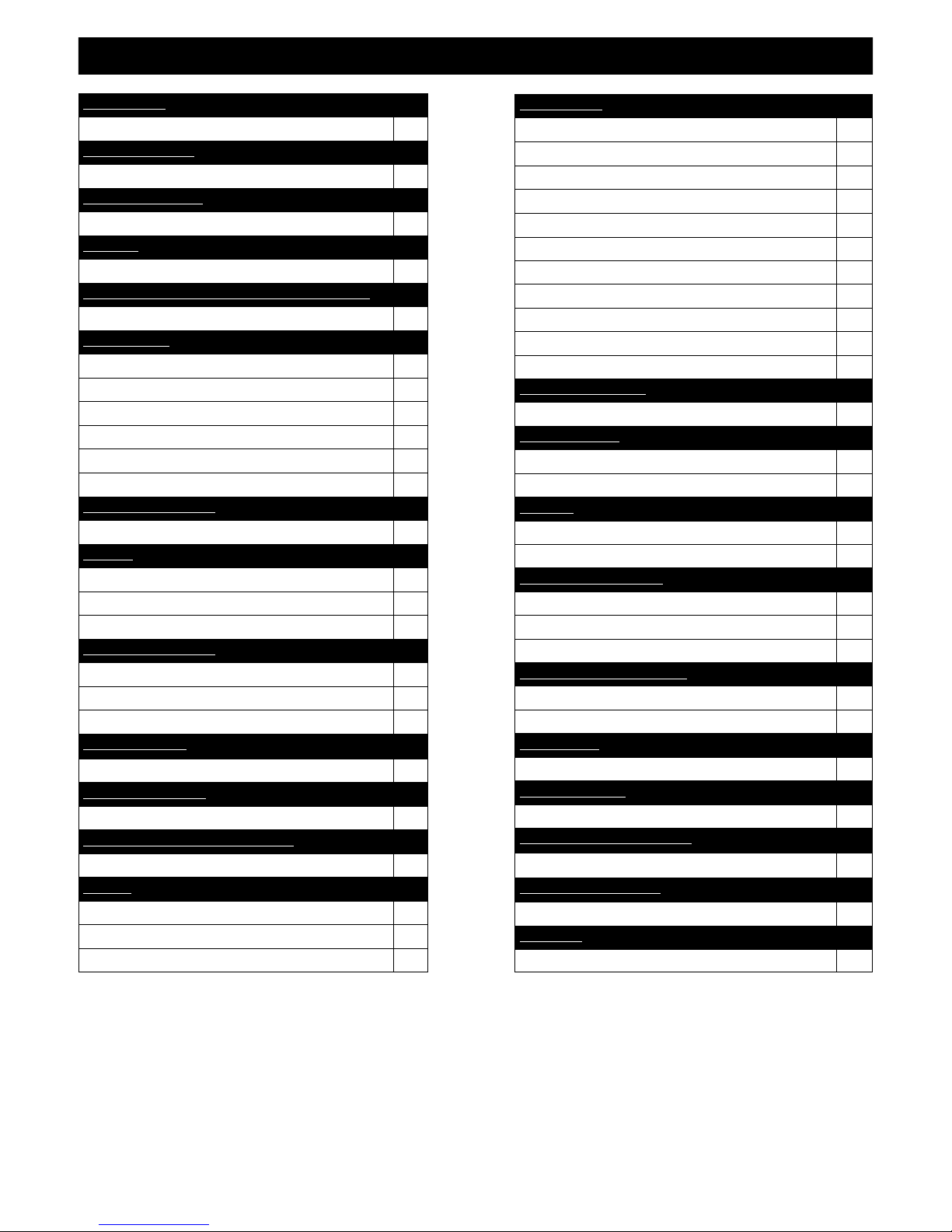
TABLE OF CONTENTS
INTRODUCTION
Introduction and Homeowner Reference Information 1
TABLE OF CONTENTS
Table of Contents 2
SAFETY INFORMATION
Safety Information 3
FEATURES
Features 4
COMMONWEALTH OF MASSACHUSETTS INFORMATION
Commonwealth of Massachusetts Information 5
SPECIFICATIONS
Fireplace Dimensions 6
Clearances 7
Windom Corner Cabinet Specifications 8
Components List 9
Installation Overview 9
Placement Clearance Requirements 9
MANTEL REQUIREMENTS
Mantel Requirements 10
FRAMING
Wall Enclosure Rough Opening 10
Vertical Terminations 11
Horizontal Terminations 11
PREPARE THE FIREPLACE
Nailing Flange Assembly and Installation 12
Glass Frame Assembly Removal 12
Glass Frame Assembly Installation 12
FAN INSTALLATION
WDM-028 Optional Fan Installation 13
GAS LINE CONNECTION
Gas Line Connection 14
THERMOSTAT / WALL SWITCH / REMOTE
Thermostat / Wall Switch / Remote 15
VENTING
Approved Venting 16
Horizontal Vent System Clearances 16
Min. / Max. Horizontal Vent System Information 16
VENTING (cont.)
Vertical Vent System Clearances 16
Min. / Max. Vertical Vent System Information 16
Horizontal / Vertical Combination Venting 16
Elbows 16
Restrictor Installation (prior to termination) 17
Horizontal Venting Illustrations 17
Corner Horizontal Venting Illustrations 18
Maximum Vertical Venting 19
Horizontal / Vertical Combination Venting Illustration 19
Termination Cap Location 20
Vertical Cap Requirements 21
LOG SET INSTALLATION
Log Set Installation 22
MILLIVOLT BOARD
Millivolt Board Removal 23
Millivolt Board Installation 23
GRILL SET
Grill Set Installation 24
Grill Set Removal 24
OPERATING INSTRUCTIONS
Valve and Pilot Assembly Components 25
Lighting and Shutdown Instructions 26-28
Pressure Testing 29
FINALIZING THE INSTALLATION
Burner Tube Venturi Adjustment / Troubleshooting 30
Restrictor Troubleshooting / Installation after Termination Completion 31
MAINTENANCE
Maintenance 32
TROUBLESHOOTING
Troubleshooting 33-35
CONVERSION KIT INSTRUCTIONS
Conversion Kit Instructions 36-37
REPLACEMENT PARTS LIST
Replacement Parts List 38
WARRANTY
Warranty 39-40
2
SAFETY INFORMATION
This fireplace has been tested by OMNI-Test Laboratories, Portland, Oregon and complies with:
ANSI Z21.88-2009/CSA 2.33-2009, “Standard for Vented Gas Fireplace Heaters”.
CAN/CGA 2.17-M91 (R2009), “Gas-Fired Appliances for Use at High Altitudes”.
CAN/CSA P.4.1-09, “Testing Method for Measuring Annual Efficiency”.
This installation must conform with local codes, or in the absence of local codes, with the National Fuel Gas Code, ANSI Z223.1/NFPA 54,
or the Natural Gas and Propane Installation Code, CSA B149.1
Installation and repair should be done only by a qualified service person. The appliance should be inspected by a
qualified service person before use. Annual inspection by a qualified service person is required to maintain warranty.
More frequent cleaning may be required due to excessive lint from carpeting, bedding materials, etc. It is imperative
th a t cont rol co m partme n ts, b u rners a nd cir c ulati o n air p assag e w ays of t he app l iance b e kep t clea n .
If this appliance is installed directly on carpeting, tile or other combustible material other than wood flooring, the
appliance shall be installed on a metal or wood panel extending the full width and depth of the appliance.
Children and adults should be alerted to the hazards of high surface temperatures and should stay away to avoid burns
or clothing ignition.
Young children should be carefully supervised when they are in the same room as the appliance. Toddlers, young
children and others may be susceptible to accidental contact burns. A physical barrier is recommended if there are at
risk individuals in the house. To restrict access to a fireplace or stove, install an adjustable safety gate to keep toddlers ,
young children and other at risk individuals out of the room and away from hot surfaces.
Clothing or other flammable material should not be placed on or near the appliance.
Adequate accessibility clearances for servicing and proper operation must be maintained.
This appliance must not share or be connected to a chimney flue serving any other appliance.
Keep area around the appliance clear of combustible materials, gasoline and other flammable vapor and liquids.
The flow of combustion and ventilation air must not be obstructed.
Due to high temperatures the appliance should be located out of traffic and away from furniture and draperies.
The glass front or any part removed for servicing the appliance must be replaced prior to operating the appliance.
Work should be done by a qualified service technician.
Clean glass only when cool and only with non-abrasive cleansers.
WARNING: DO NOT OPERATE APPLIANCE WITH THE GLASS/FRAME ASSEMBLY REMOVED, CRACKED
OR BROKEN. REPLACEMENT OF THE GLASS SHOULD ONLY BE PERFORMED BY A LICENSED OR
QUALIFIED SERVICE PERSON .
The glass assembly, Part #700-07T, shall only be replaced as a complete unit, as supplied by Hussong Mfg. Co., Inc.
DO NOT SUBSTITUTE MATERIALS.
Do not strike or slam glass assembly.
Any safety screen or guard removed for servicing the appliance must be replaced prior to operating the appliance.
Under no circumstances should any solid fuel (wood, coal, paper or cardboard etc.) be used in this appliance.
Keep burner and control compartment clean.
Do not use this fireplace if any part has been under water. Immediately call a qualified service technician to inspect this
appliance and to replace any part of the control system and any gas control which has been under water.
3
FEATURES
STANDARD FEATURES
High efficiency
Zero clearance
High quality lifetime glass
17” x 30” (432mm x 762mm)
Quick latch glass frame assembly
Upper & lower grill (black)
Patented burner design
High - Low regulator
Patented log design
Minnesota Energy Code compliant to 50 pascals
OPTIONAL FEATURES
Automatic fan kit with variable speed control (2) - 75 CFM
Firebrick refractory
Remote control or thermostat remote control
Wall mount thermostat / wireless wall mount thermostat
Decorative full door faces / screen doors in various styles and
finishes
Rectangular valance
Interior / Exterior trim
Various grill designs and finishes
SAFETY FEATURES
Each unit factory tested!
Tested by OMNI - Test Laboratories
Sealed combustion chamber with standing pilot ignition
Removable millivolt board with 30-second delay pilot
Automatic pressure relief glass system
Requires no electricity to operate
(excluding fan)
Bedroom and mobile home approved
Canadian approved
WEIGHT
Fireplace Weight (as packaged for shipment)
131 lbs. (59.4 kg)
4

COMMONWEALTH OF MASSACHUSETTS REQUIREMENTS
NOTE The following requirements reference various Massachusetts and national codes not contained in this manual.
For all sidewall horizontally vented gas fueled equipment installed in every dwelling, building or structure used in whole or in part for residential purposes,
including those owned or operated by the Commonwealth and where the side wall exhaust vent termination is less than (7) feet above finished grade in the
area of the venting, including but not limited to decks and porches, the following requirements shall be satisfied:
INSTALLATION OF CARBON MONOXIDE DETECTORS
At time of installation of side wall horizontally vented gas fueled equipment, the installing plumber or gas-fitter shall observe that a hard wired carbon
monoxide detector with an alarm and battery back-up is installed on the floor level where the gas equipment is to be installed. In addition, the installing
plumber or gas-fitter shall observe that a battery operated or hard wired carbon monoxide detector is installed on each additional level of the dwelling,
building or structure served by the side wall horizontal vented gas fueled equipment. It shall be the responsibility of the property owner to secure the services
of qualified licensed professionals for the installation of hard wired carbon monoxide detectors.
In the event that the side wall horizontally vented gas fueled equipment is installed in a crawl space or attic, the hard wir ed carbon monoxide detector with
alarm and battery back-up may be installed on the next adjacent floor level.
In the event that the requirements of this subdivision can not be met at the time of completion of installation, the owner shall have a period of thirty (30) days
to comply with the above requirements; provided, however, that during said thirty (30) day period, a battery operated carbon monoxide detector with an
alarm shall be installed.
APPROVED CARBON MONOXIDE DETECTORS
Each carbon monoxide detector as required in accordance with the above provisions shall comply with NFPA 720 and be ANSI/UL 2 034 listed and IAS
certified.
SIGNAGE
A metal or plastic identification plate shall be permanently mounted to the exterior of the building at a minimum of eight (8 ) feet above grade directly in line
with the exhaust vent terminal for the horizontally vented gas fueled heating appliance or equipment. The sign shall read, in print no less the one-half inch
(1/2) in size, “GAS VENT DIRECTLY BELOW. KEEP CLEAR OF ALL OBSTRUCTIONS”.
INSPECTION
The state or local gas inspector of the side wall horizontally vented gas fueled equipment shall not approve the installation unless, upon inspection, the
inspector observes carbon monoxide detectors and signage installed in accordance with the provisions of 24 8 CMR 5.08 (2) (a) 1 through 4.
EXEMPTIONS
The following equipment is exempt from 248 CMR 5.08 (2) (a) 1 through 4:The equipment listed in Chapter 10 entitled “Equipmen t Not Required To Be
Vented” in the most current edition of NFPA 54 as adopted by the Board; and Product Approved side wall horizontally vented gas fueled equipment installed
in a room or structure separate from the dwelling, building or structure used in whole or in part for residential purposes.
MANUFACTURER REQUIREMENTS - GAS EQUIPMENT VENTING SYSTEM PROVIDED
When the manufacturer of Product Approved side wall horizontally vented gas equipment provides a venting system design or venting system components
with the equipment, the instructions provided by the manufacturer for installation of the equipment and the venting system shall include:
Detailed instructions for the installation of the venting system design or the venting system components; and
A complete parts list for the venting system design or venting system.
MANUFACTURER REQUIREMENTS - GAS EQUIPMENT VENTING SYSTEM NOT PROVIDED
When the manufacturer of Product Approved side wall horizontally vented gas equipment does not provide the parts for venting the flue gases, but identifies
“special venting systems”, the following requirements shall be satisfied by the manufacturer:
The referenced “special venting systems” instructions shall be included with the appliance or equipment installation instructions and;
The “special venting systems” shall be Product Approved by the Board, and the instructions for that system shall include a parts list and detailed
installation instructions.
A copy of all installation instructions for all Product Approved side wall horizontally vented gas fueled equipment, all venting instructions, all parts lists for
venting instructions, and/or all venting design instructions shall remain with the appliance or equipment at the completion of the installation.
5
32"
812mm
11"
279mm
19
1
2
"
495mm
2"
51mm
5
1
4
"
133mm
3
5
8
"
92mm
2
3
4
"
70mm
23
3
8
"
594mm
11"
279mm
23
3
8
"
594mm
32"
812mm
11"
279mm
19
1
2
"
495mm
1
3
4
"
44mm
2"
51mm
1
1
8
"
29mm
2
3
4
"
70mm
4
3
4
"
121mm
5
1
4
"
133mm
3
5
8
"
92mm
2
3
4
"
70mm
23
3
8
"
594mm
2"
51mm
5
1
4
"
133mm
3
5
8
"
92mm
2
3
4
"
70mm
22
3
8
"
568mm
23
3
8
"
594mm
30
1
8
"
765mm
FIREPLACE
DIMENSIONS
SPECIFICATIONS
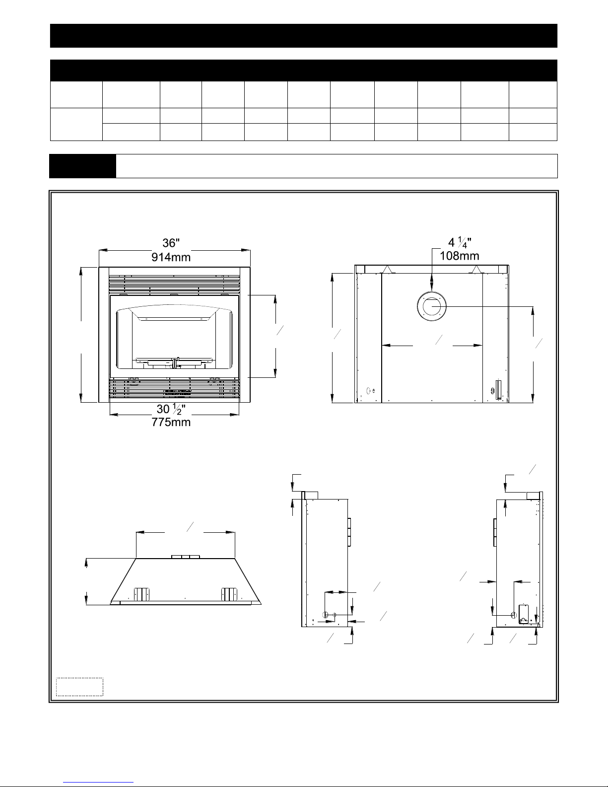
FIREPLACE DIMENSIONS
DESCRIPTION Height Width Depth Glass Frame
INCHES 32 36 11 19-1/2 2 22-3/8 4-1/4 4-3/4 2-3/4
MILLIMETERS 812 914 279 495 51 568 108 121 70
Height
Stand-off
Height
Vent Center
from floor
Vent Center to
unit top
Back to Gas
Line Hole Center
(left side)
Floor to Gas Line
Hole Center
WARNING
Top stand-off bracket must be attached to fireplace. Do not remove. Stand-off brackets are not load bearing.
Other clearances apply. All clearances must be maintained.
FRONT
BACK
TOP
Figure 6a
6
RIGHT
LEFT

SPECIFICATIONS
WARNING
CLEARANCES
Top stand-off bracket must be attached to fireplace. Do not remove. Stand-off brackets are not load bearing.
Other clearances apply. All clearances must be maintained.
From unit left & right sides and back 0” (0mm)
From unit top stand-offs 0” (0mm)
To flooring 0” (0mm)
Unit side to adjacent sidewall* 0” (0mm)
Top of unit to 3/4” (19mm) trim 1” (25mm)
Mantel 10” (254mm) deep from top of fireplace 9” (229mm)
*Provide adequate room for servicing and component access.
NOTE 1/4” (6mm) expansion space included in dimensions. 1/2” (13mm) wall materials included in dimensions where applicable.
1” (25mm) clearance sides
36-1/2” (927mm)
11-1/4” (286mm)
35-5/8” (905mm)
36-1/2” (927mm)
2-1/4” (57mm)
1”(25mm)
1” (25mm) clearance sides
54-3/4” (1391mm)
1” (25mm)
22-3/8” (568mm)
1-1/2” (38mm) clearance top
1” (25mm) clearance
11-1/4” (286mm)
36-1/2” (927mm)
Figure 7a
7
SPECIFICATIONS
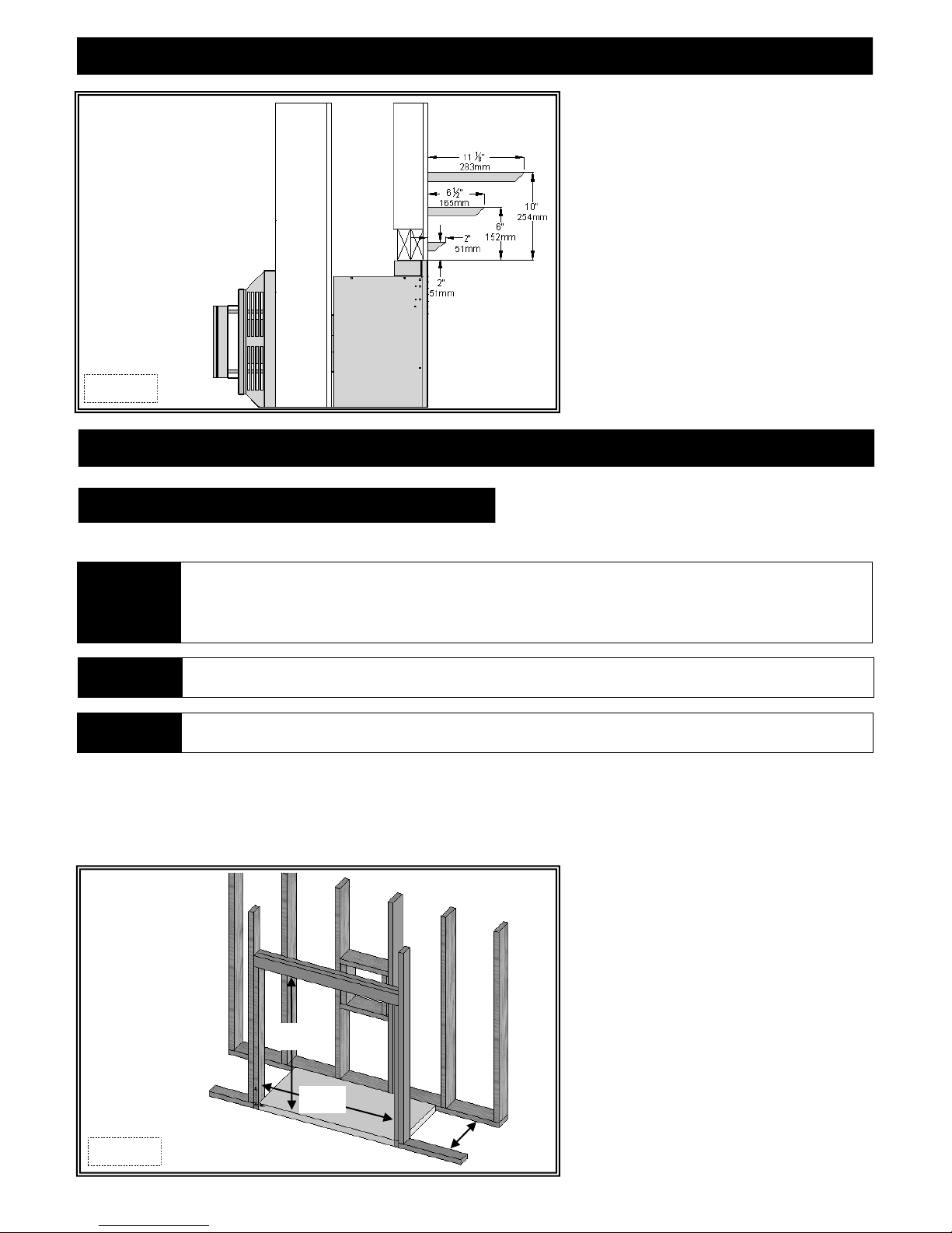
NOTE 1” (25mm) clearance from vent system framing to finished wall and 2-1/4” (57mm) from vent pipe to finished wall are required.
FIREPLACE POSITIONING (IF USING WINDOM CORNER CABINET)
1” (25mm) clearance at sides
1” (25mm)
2-1/4” (57mm)
32” (813mm)
37-3/4” (959mm)
Figure 8a
WINDOM CORNER CABINET DIMENSIONS
1” (25mm) clearance at sides
1” (25mm)
2-1/4” (57mm)
32-5/8” (829mm)
5-1/4” (133mm)
38-3/8” (975mm)
Figure 8b
5-1/2” (140mm)
8
SPECIFICATIONS
#56101 COMPONENTS LIST
PART NUMBER DESCRIPTION
WDM-770 Millivolt Control Board Assembly
700-203 Manual Gas Shut-off Valve
OCK-035 Burner Assembly
WDM-50B Log Package
936-005 Glass Valance
700-07T Glass with Gasket
OCK-S55A LP Conversion Kit
600-083 Receptacle / Speed Control Assembly
900-085 4” Restrictor Plate
INSTALLATION OVERVIEW
NOTE The qualified installer should follow the procedure best suited for the installation.
1. Frame an opening for the fireplace, allowing for vent installation and type of installation.
2. If masonry (optional) is used, prepare foundation for the masonry load. A lintel is required to support the added weight above fireplace.
3. Attach nailing flanges to fireplace.
4. Insert fireplace into framing.
5. Install hearth (if applicable).
6. Complete gas line installation.
7. Complete electrical hook-up. Install any standard or optional electrical components at this time.
8. Complete venting installation.
9. Secure fireplace to flooring through holes in outer box bottom and to framing with nailing flanges. Verify all clearances at this point.
10. Install facing material, mantel or cabinetry, allowing room for optional full face doors, if applicable.
11. Install logs.
12. Install grills and optional decorative doors / faces.
13. Verify proper operation of fireplace and all components.
PLACEMENT CLEARANCE REQUIREMENTS
This fireplace must be installed on a level surface capable of supporting the fireplace and venting.
Fireplace must be placed directly on wood or non-combustible surface (not linoleum or carpet) extending the entire depth and width of
fireplace.
Due to high surface temperatures, fireplace should be located out of traffic and away from furniture and draperies.
This fireplace may be installed in a bedroom.
Please be aware of the large amount of heat this fireplace will produce when determining a location.
9
MANTEL REQUIREMENTS
Figure 10a
FRAMING
WALL ENCLOSURE ROUGH OPENING
Applies to horizontal and vertical vent terminations: 32-1/4” (819mm) High x 36-1/2”(927mm) Wide x 11-1/4” (286mm) Deep.
Framing dimensions should allow for wall covering thickness and fireplace facing materials. If using a hearth, adjust rough
IMPORTANT
NOTE
WARNING
opening size as necessary to maintain at least minimum clearance requirements.
Non-combustible facing material may be applied over (but not directly to) fireplace face. This will prevent facing material from
falling off due to heat expansion. Do not obstruct the flow of ventilation air.
Provide adequate clearance in front of fireplace to operate lower grill, open and close optional decorative doors / full door faces,
access components, installation of gas line, fan, etc.
Do not obstruct upper and lower grill openings. Room air enters through lower passage, is heated and exits through upper
passage. Blocking these passages may result is overheating, creating a potentially hazardous situation.
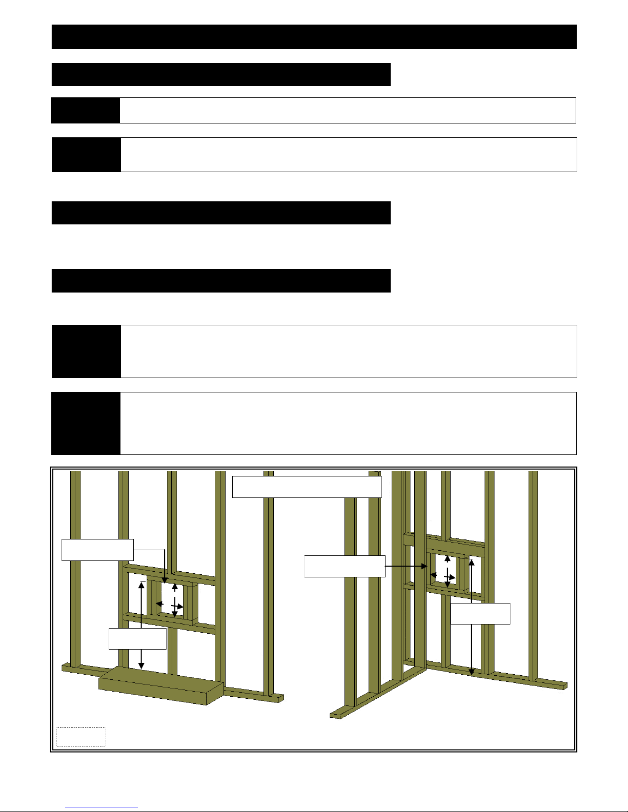
Determine exact position of your fireplace, including hearth height, width, and depth, (if applicable). If possible, place fireplace in such a
manner that vent termination will be placed between two studs, eliminating the need for additional framing.
If masonry is to be used (optional), prepare foundation for the masonry load. When masonry construction is being used, linte l (#617) must
be used over top of fireplace to support the added weight.
32-1/4”
(819mm)
36-1/2”
(927mm)
Figure 10b
11-1/4”
(286mm)
10
FRAMING
HEARTH EXTENSION REQUIREMENTS
NOTE
Consider height of hearth finish material (stone, brick, etc.) when building fireplace platform. Bottom of fireplace must be level
with finished hearth to allow for lower grill operation and proper fit of optional decorative full door faces.
Install fireplace on hard metal or wood surface extending the full width and depth of fireplace. Minimum platform size:
WARNING
36” (914mm) wide x 11” (610mm) deep.
Do NOT install directly on carpeting, vinyl, or any combustible material other than wood.
Build hearth to desired size and height. If a hearth extension is desired, combustible material may be used.
VERTICAL TERMINATIONS
Follow vent pipe manufacturer‟s installation instructions for vertical terminations. A minimum 1” (25mm) clearance on all sides of vertical
vent pipe must be maintained.
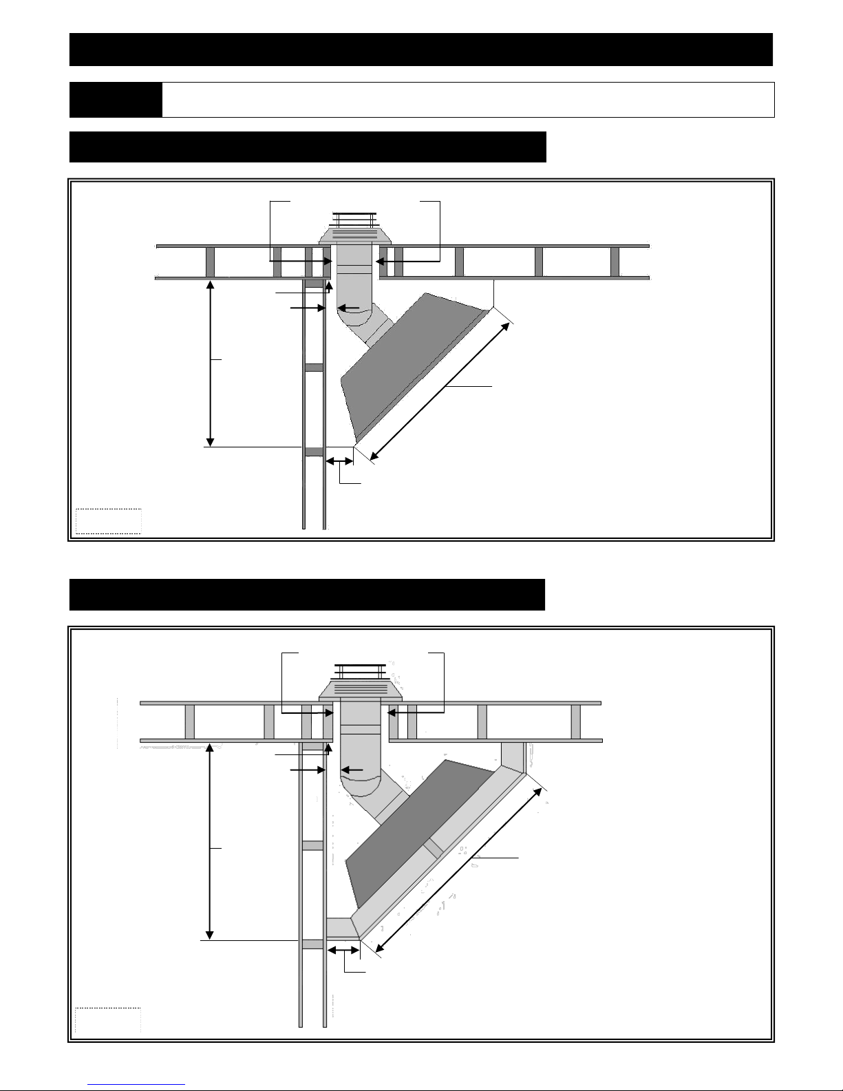
HORIZONTAL TERMINATIONS
Follow vent pipe manufacturer‟s installation instructions for horizontal terminations. Include the required 1 -1/2” (38mm) top clearance (at
wall pass-thru) and 1” (25mm) sides and bottom clearances for approved rigid vent systems.
To achieve minimum venting requirements, a minimum of 26” (660mm) from floor or hearth the fireplace is setting on to top of
IMPORTANT
CAUTION
vent pipe is required.
Wall pass-thru required for all horizontal runs. Refer to vent manufacturers' to determine which pass-thru will work best for
your application and wall thickness.
Cold air transfer area. The surrounding fireplace chase must comply with all clearances as outlined in this manual and be
constructed in compliance with local building codes. Outside walls should be insulated to prevent cold air from entering room.
Due to high temperatures, this fireplace should be located out of traffic areas and away from furniture and draperies.
Vent cap location must be in compliance with the guidelines on page #20 of this manual.
Top of wall pass-thru
1-1/2” (38mm) clearance
H
W
26” (660mm) min.
to top of vent pipe
TYPICAL HORIZONTAL TERMINATION
Figure 11a
Refer to vent pipe manufacturer’s instructions for
specific height (H) and width (W) framing dimensions.
Inside framing to stud wall
1-1/2” (38mm)
H
W
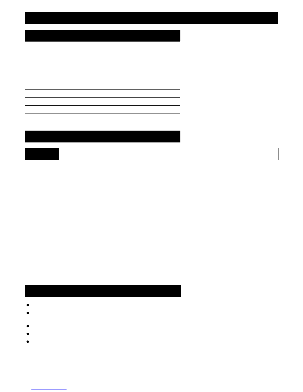
39” (991mm) to top
of framing
KOZY HEAT CORNER CABINET FRAMING
11

PREPARE THE FIREPLACE
NAILING FLANGE ASSEMBLY & INSTALLATION
1. Remove (4) nailing flanges from fireplace sides.
2. With the 1/4” (6mm) stand-offs on nailing flanges facing away from fireplace, align nailing flange with holes on outside corners of
fireplace. Secure with screws (provided in components packet) through slots in nailing flanges.
3. Bend perforation on nailing flange until parallel with fireplace face. Do not bend toward fireplace face.
4. Position framing stud against 1/4” (6mm) stand-off (located on backside of nailing flange). Secure with nails or screws.
NOTE Depending on facing material, nailing flanges can be adjusted forward or backwards up to 1/2” (13mm).
CAUTION Never permanently remove these assemblies from fireplace. They must be secured in place regardless of finish material used.
1/4” (6mm) CLEARANCE
STAND-OFF
1/4” (6mm) CLEARANCE
STAND-OFF
NAILING FLANGE
FRAMING STUD
Figure 12a
FRONT VIEW
TOP VIEW
GLASS FRAME ASSEMBLY
DO NOT OPERATE THIS FIREPLACE WITH GLASS REMOVED, CRACKED OR BROKEN. REPLACEMENT OF GLASS ASSEMBLY,
WARNING
REMOVE GLASS FRAME ASSEMBLY
Remove upper grill and open lower grill before removing glass frame assembly.
A. Locate spring-loaded handles securing glass frame assembly at bottom of firebox.
B. Pull bottom handles out and down to release glass frame assembly bottom.
C. Pull bottom of glass frame assembly out and lift up off tabs at top of firebox.
#700-07T SHOULD BE DONE BY A LICENSED OR QUALIFIED SERVICE PERSON.
DO NOT REMOVE GLASS ASSEMBLY WHEN HOT!
FRAMING STUD
NAILING FLANGE
INSTALL GLASS FRAME ASSEMBLY
A. Place glass frame assembly top over tabs at top of firebox.
B. Pull bottom handles out and up to secure glass frame assembly bottom.
Figure 12b
12
OPTIONAL FAN INSTALLATION
INSTALLATION OF THIS FAN SHOULD BE DONE ONLY BY A QUALIFIED INSTALLER
MAKE SURE HOUSEHOLD BREAKER IS SHUT OFF PRIOR TO WORKING ON ANY ELECTRICAL LINES.
WARNING
IMPORTANT
NOTE
Optional fan kit #WDM-028 includes: (2) 75 CFM fan with temperature control switch and 4ft. (1219mm) fan cord
(4) 1/4” nuts
1. Remove upper hood, upper louver & lower grill, if installed. Page 24.
2. Remove glass assembly. Page 12.
3. Insert fans through lower grill opening on left side of gas valve. Push to back of fireplace. Align mounting slots in fan brackets with
mounting studs. Secure with nuts.
4. From inside lower right grill opening, loosen screw securing removable access panel (with electrical box & romex connector installed).
Remove panel.
5. Insert 115V wiring (with ground) through romex connector and wire to speed control / receptacle assembly matching black (hot), white
(neutral), and green (ground) wires to corresponding wires on speed control / receptacle assembly.
6. Secure speed control / receptacle assembly to electrical box with (2) screws provided.
7. Re-install electrical access panel. Tighten screw.
8. Attach temperature control switch to bottom of firebox.
9. Plug cord into electrical box receptacle.
10. Turn speed control counter-clockwise until it „clicks‟. This is the OFF position.
11. Turn speed control ON by turning knob clockwise past the „click‟ - this is the highest setting.
12. Re-install glass assembly, lower grill, upper louver & upper hood.
THIS APPLIANCE IS EQUIPPED WITH A THREE-PRONG (GROUNDING) PLUG FOR PROTECTION AGAINST SHOCK HAZARD AND
SHOULD BE PLUGGED DIRECTLY INTO A PROPERLY GROUNDED THREE-PRONG RECEPTACLE. DO NOT CUT OR REMOVE
GROUNDING PRONG FROM THIS PLUG.
If installing a fan, it is easier to complete prior to connecting millivolt board to gas supply. Wiring must be done before enclosing fireplace sides.
An electrical box and romex connector are pre-installed on a removable panel on right side of fireplace. A receptacle / speed control assembly and
(3) wire nuts are included in fireplace components packet.
Code approved line voltage wiring 14 gauge or better must be used when wiring this assembly.
Refer local electrical codes for specific requirements.
This appliance must be electrically grounded and c onnected in accordance with local codes, or in the absence of local codes, with the National
Electrical Code, ANSI/NFPA 70 Current Edition, or the Canadian electrical Code CSA C22.1.
This fan will not operate unless speed control has been turned ON and sufficient heat has been applied to temperature control switch. The fan will
turn ON and OFF automatically as fireplace heats and cools. Adjust fan to desired speed while it is running.
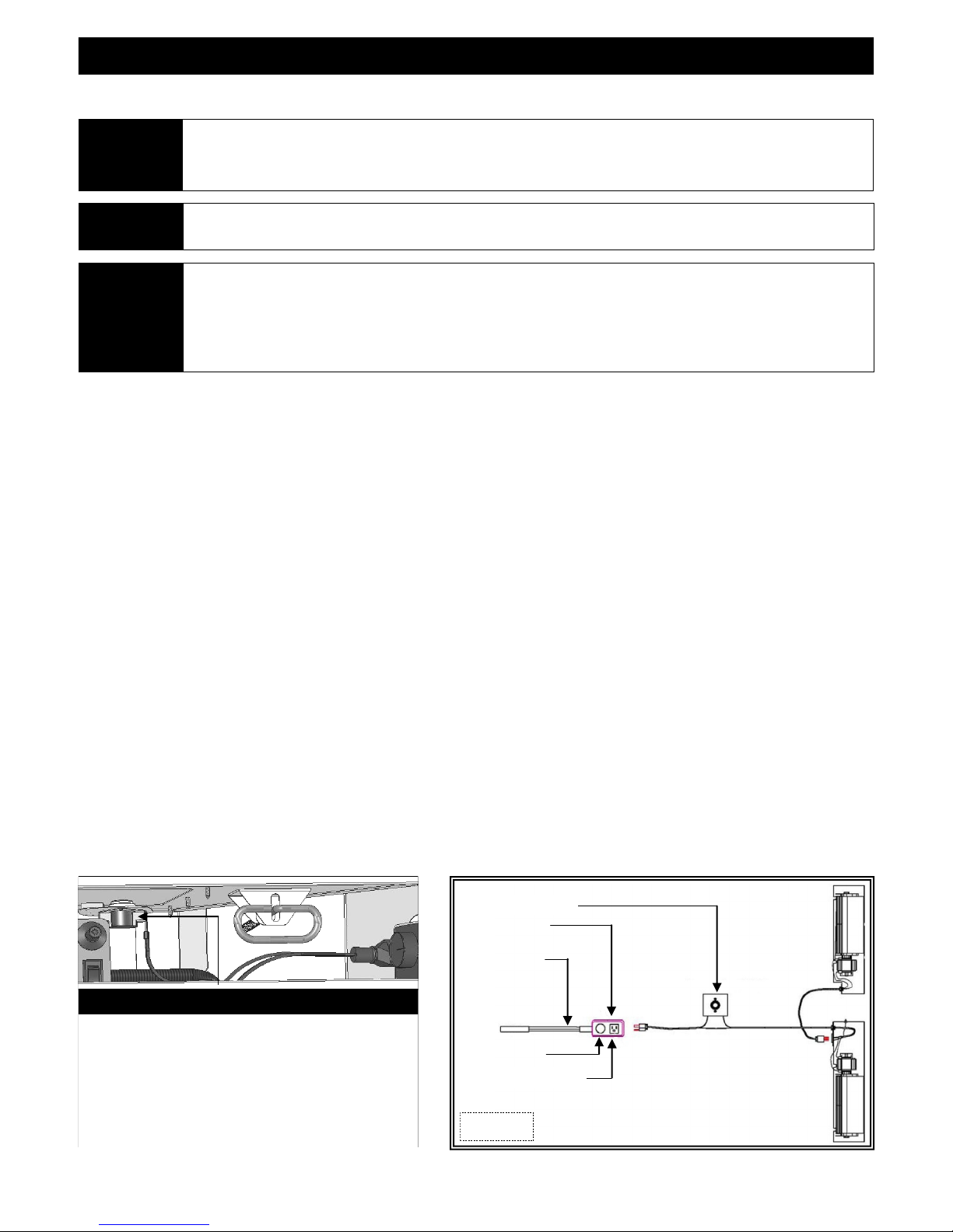
TEMPERATURE CONTROL SWITCH POSITION
Before adjusting temperature control switch, unplug 3-prong plug
on fan cord from receptacle. Adjust position of temperature
control switch to a warmer location under firebox to turn fan ON
sooner or move it to a cooler location under firebox to turn fan
ON later. The fan will turn on when sensor in temperature control
switch reaches 110° F and will turn OFF when sensor reaches 90°
F. After adjustment, insert fan cord 3-prong plug into receptacle.
Temperature Switch
Electrical Box
Incoming wiring60Hz
110V-120V
Speed Control
Receptacle Assembly
Figure 13a
13
GAS LINE CONNECTION
GAS CONVERSION
This fireplace is manufactured for use with Natural Gas. An LP conversion kit, is included with this fireplace. Follow instructions included
with conversion kit if converting to LP gas.
ATTENTION
CAUTION
NOTE
IMPORTANT
NATURAL GAS LP GAS
The conversion shall be carried out in accordance with the requirements of the provincial authorities having jurisdiction and in
accordance with the requirements of the ANSI Z223.1 installation code.
Installation of the gas line must only be done by a qualified person in accordance with local building codes, if any.
If not, follow ANSI 223.1.
Commonwealth of Massachusetts: Installation must be done by a licensed plumber of gas fitter.
A listed (and Commonwealth of Massachusetts approved) 1/2” (13mm) T-handle manual shut-off valve and flexible gas
connector (included) are connected to the 1/2” (13mm) control valve inlet. If substituting for these components, please consult
local codes for compliance.
This fireplace is equipped with a 3/8” (10mm) x 18” (457mm) long flexible gas connector and manual shut-off valve. The gas
line should be run to the point of connection where the shut-off valve and flexible gas line will connect.
The appliance and its individual shutoff valve must be disconnected from the gas supply piping system during any pressure
testing of that system at pressures in excess of ½ psi (3.5 kPa).
The appliance must be isolated from the gas supply piping system by closing its individual manual shut-off valve during any
pressure testing of the gas line at test pressures equal to or less than ½ psi (3.5 kPa).
For high altitude installations, consult the local gas distributor or the authority having jurisdiction for proper rating methods.
The efficiency rating of this appliance is a product of thermal efficiency rating determined under continuous operating
conditions and was determined independently of any installed system.
MINIMUM INLET GAS PRESSURE 5” WC (1.25 kPa) (7” WC (1.74 kPa) recommended) 11” WC (2.74 kPa) (recommended)
MAXIMUM INLET GAS PRESSURE 10.5” WC (2.62 kPa) 13” WC (3.24 kPa)
MANIFOLD PRESSURE (HI) 3.5” WC (.87 kPa) 10” WC (2.49 kPa)
MANIFOLD PRESSURE (LO) 1.1” WC (.27 kPa) 6.3” WC (1.57 kPa)
ORIFICE SIZE #42 #55
INPUT BTU/hr. (kW) 23,000 BTU/hr (7.74 kW) 19,000 BTU/hr (5.57 kW)
MINIMUM INPUT BTU/hr. (kW) 16,000 BTU/hr (4.69 kW) 14,000 BTU/hr (4.1 kW)
HIGH ALTITUDE INSTALLATIONS
In the USA: The appliance may be installed at higher altitudes. Please refer to your American Gas Association
guidelines which state: the sea level rated input of Gas Designed Appliances installed at elevations above 2000ft. (610m)
ATTENTION
is to be reduced 4% for each 1000ft. (305m) above sea level. Refer also to National Fuel Gas Code, ANSI Z223.1/ NFPA
54 , loc al author i ties , or cod es which have jur i sdic tion in your area regardin g th e de - r ate guid e line s.
In Canada: When the appliance is installed at elevations above 4500ft. (1372m), the certified high altitude rating shall
be reduced at the rate of 4% for each additional 1000ft. (305m). Refer also to CSA-B149.1 Natural Gas and Propane
Installation Code, Local authorities, or codes which have jurisdiction in your area regarding the de-rate guidelines.
14
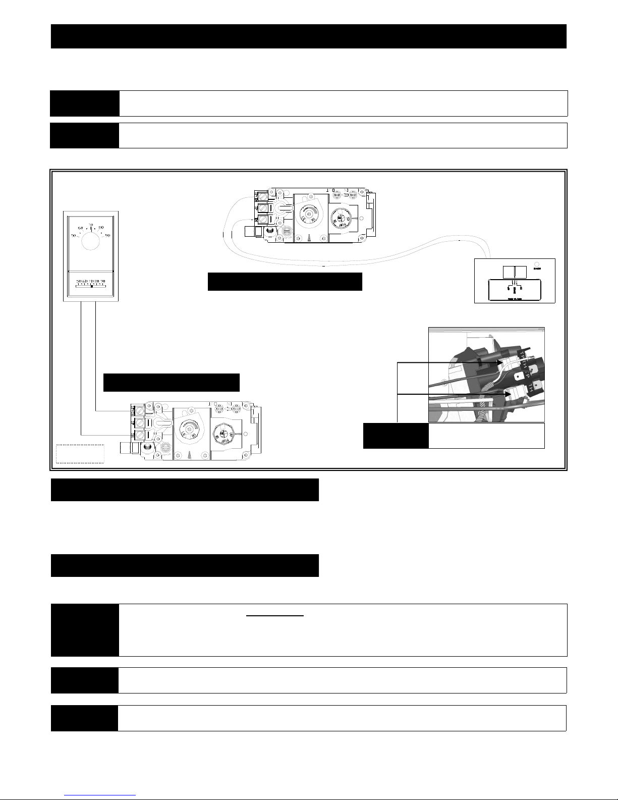
THERMOSTAT / WALL SWITCH / REMOTE
If desired, a thermostat (wireless style also available), wall switch, or remote control assembly may be used to turn fireplace OFF and ON.
Only ONE of these may be installed. Follow instructions included with chosen assembly.
NOTE
CAUTION
INSTALLATION OF THERMOSTAT OR WALL SWITCH SHOULD ONLY BE DONE BY A QUALIFIED INSTALLER.
DO NOT CONNECT HIGH VOLTAGE (115V) WIRE TO THE GAS VALVE!
Remote Control Wiring Diagram
Thermostat Wiring Diagram
OPTIONAL
Figure 15a
Disconnect ON/OFF rocker switch
wires from back of gas valve.
WALL SWITCH / THERMOSTAT:
Run low-voltage (thermostat) wires from terminals on gas valve to desired location of wall switch or thermostat.
Attach appropriate connectors to wall switch / thermostat wires and connect to top and bottom terminals marked TH/TPTH on gas valve.
REMOTE CONTROL:
Follow instructions included with remote control.
If ON/OFF rocker switch wires are not disconnected, the ON/OFF rocker switch on millivolt board must be in OFF position for
IMPORTANT
NOTE
IMPORTANT The insulated cover included with remote control must be placed over remote receiver to prevent overheating.
proper operation of any of these components.
If rocker switch is ON, fireplace burner will operate until it is turned OFF by rocker switch. A wall switch, thermostat, or
remote control will not turn fireplace OFF when it has been turned ON by the rocker switch.
Fireplace must be turned ON and OFF by same method. For example: If fireplace is turned ON by remote control, it must be
turned OFF by remote control.
15
VENTING
Consult the local and national installation codes to assure adequate combustion and ventilation air is available.
IMPORTANT
Refer to the vent systems manufacturer's installation manual for complete installation instructions.
Installation must conform with the venting requirements and restrictions as outlined in this manual.
Simpson Dura-Vent DV-GS 4” x 6-5/8” direct vent system (horizontal and vertical terminations).
Ameri-Vent Direct Chimney System 4” x 6-5/8” (horizontal and vertical terminations).
Selkirk Metalbestos Chimney System 4” x 6-5/8” (horizontal and vertical terminations).
Metal Fab Chimney System: 4” x 6-5/8” (horizontal and vertical terminations).
ICC Chimney System: 4” x 6-5/8” (horizontal and vertical terminations).
This fireplace is designed to be used with rigid pipe only.
1-1/2 inches (38mm) at wall pass thru 1 inch (25mm) 1 inch (25mm)
Flame height and appearance will vary depending upon venting configuration and type of fuel used.
Venting requirements apply to both Natural and LP gas.
HORIZONTAL VENT SYSTEM CLEARANCES
TOP BOTTOM SIDES
WARNING
A WALL PASS-THRU MUST BE USED ON ALL HORIZONTAL VENT RUNS.
HORIZONTAL TERMINATIONS
MINIMUM: 6” (152mm) horizontal + termination cap.
MAXIMUM: 20ft. (6.096m) horizontal + termination cap.
VERTICAL TERMINATIONS
MINIMUM VERTICAL: 0” (0mm).
MAXIMUM VERTICAL: 90˚ elbow + 28ft. (8.534m) vertical + termination cap.
Maintain 1” (25mm) clearance on all sides of pipe.
HOR. / VERT. COMBINATION TERMINATIONS
PLEASE REFER TO VENTING CHART ON PAGE 18.
ELBOWS
NOTE
For each additional 90° elbow used after the first elbow, 3ft. (914mm) must be subtracted from maximum allowed venting. For each 45°
elbow used, 1-1/2ft. (457mm) must be subtracted from maximum venting allowed.
(1) 90˚ elbow is included within the maximum vent runs.
(2) 45° degree elbows may be used in place of (1) 90° elbow.
16
VENTING
RESTRICTOR INSTALLATION
Each installation is unique and affected by various factors including venting configuration, altitude and climate. Therefore, after fireplace
installation is complete a restrictor may be required or may need to be removed or modified.
Large Restrictor Bend tabs to approx. 80 degree
Figure 17a
Remove tab (s) to
create small restrictor
angles to create tension to hold
itself in place when installed.
Slide restrictor into exhaust pipe on top of
fireplace with tabs pointing towards you
prior to attaching venting.
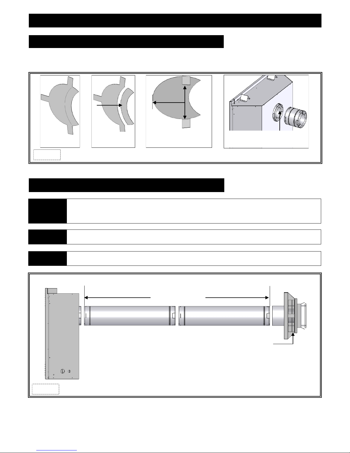
MINIMUM / MAXIMUM HORIZONTAL VENTING
Horizontal sections require 1/4” (6mm) rise for every 12” (305mm) of travel.
NOTE
CAUTION This gas appliance must not be connected to or joined with any other chimney flue serving another appliance.
WARNING A WALL PASS-THRU MUST BE USED ON ALL HORIZONTAL VENT RUNS.
Page 17 has information on restrictor installation in conjunction with venting installation. Page 31 has information on restrictor
recommendations depending on burner flame appearance and instructions on installation after venting is completed.
MINIMUM: 6in. (152mm)
MAXIMUM: 20ft. (6.096m)
Figure 17b
TERMINATION CAP
17
 Loading...