

kozy heat MPS-30 Minneapolis, JOR-30, Minneapolis XL MPS-34, Rockford XL RFD-34, JOR-34 Installation Manual
INSTALLATION MANUAL
DIRECT VENT FIREPLACE INSERT
IMPORTANT: This installation manual is to be used in conjunction with SUPPLEMENTAL
INSTALLATION AND HOMEOWNER INFORMATION MANUAL. Read both manuals before installing
and operating appliance.
INSTALLER: Leave this manual with the appliance.
CONSUMER: Retain this manual for future reference.
This appliance may be installed in an a f te rmarket permanently located,
manufactured home (USA only) or mobile home, where not prohibited by local codes.
This appliance is only for use with the type of gas indicated on the rating plate. This
appliance is not convertible for use with other gases, unless a certified kit is used.
WARNING: If the information in these instructions is not followed exactly, a fire
or explosion may result causing property damage, personal injury or loss of life.
—Do not store or use gasoline or other flammable vapors and liquids in the vicinity
of this or any other appliance.
WHAT TO DO IF YOU SMELL GAS:
◙ Do not try to light any appliance.
◙ Do not touch any electrical switch: do not use any phone in your building.
◙ Immediately call gas supplier from a neighbors phone. Follow the gas
supplier instructions
◙ If you cannot reach your gas supplier, call the fire department.
—Installation and service must be performed by a qualified installer, service agency
or the gas supplier.
English and French Installation Manuals
Available Through Your Local Dealer or
Visit Our Website at www.kozyheat.com
WARNING
HOT GLASS WILL CAUSE BURNS.
DO NOT TOUCH GLASS UNTIL COOLED.
NEVER ALLOW CHILDREN TO TOUCH GLASS.
#216-S-33b-6.5
JUNE 2012
MPS-30 REV-07
www.kozyheat.com
INTRODUCTION
Read this manual before installing or operating this appliance.
Please retain this owner’s manual for future reference.
CONGRATULATIONS!
We welcome you as a new owner of a Kozy Heat gas fireplace. Kozy Heat products are
designed with superior components and materials and assembled by trained craftsmen who
take pride in their work. The burner and valve assembly are 100% test-fired and the complete
fireplace is thoroughly inspected before packaging to ensure that you receive a quality product.
Our commitment to quality and customer satisfaction have remained the same for over 30
years. We offer a complete line of gas and wood fireplaces, unique cabinets and stylish
accessories to compliment any décor. Adding a fireplace is one of the best ways to increase the
value of your home and we are proud to offer a network of dealers throughout the country to
help make your experience everything you imagine. We pride ourselves in being dedicated to
not only function and reliability, but customer safety as well. We offer our continual support
and guidance to help you achieve the maximum benefit and enjoyment from your Kozy Heat
gas fireplace.
Jim Hussong Dudley Hussong
President Board Chairman
Homeowner Reference Information
We recommend that you record the following information about your fireplace.
Model Name:______________________________ Date purchased/installed:_____________________________________
Serial Number:____________________________ Location on fireplace:________________________________________
Dealership purchased from:__________________ Dealer Phone:______________________________________________
Notes:_______________________________________________________________________________________________
____________________________________________________________________________________________________
____________________________________________________________________________________________________
1
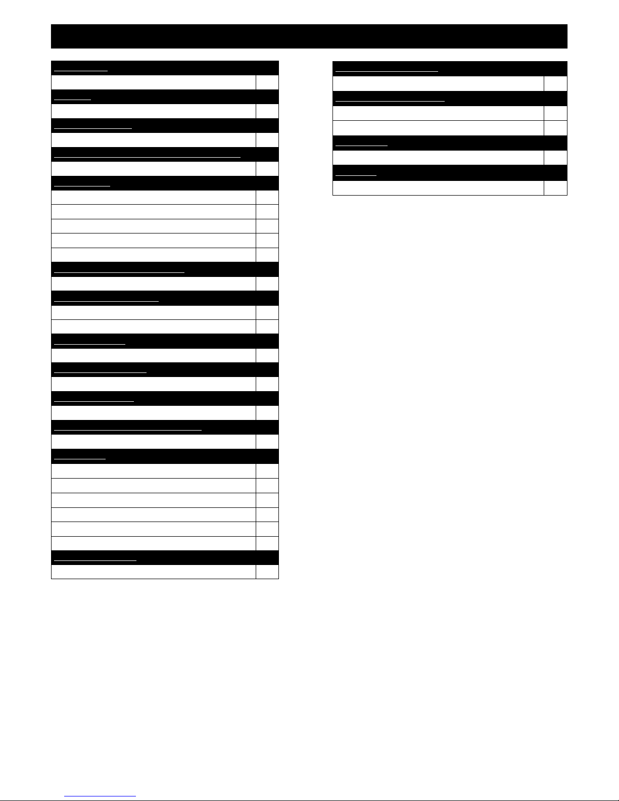
TABLE OF CONTENTS
INTRODUCTION
Introduction and Homeowner Reference Information 1
CONTENTS
Table of Contents 2
SAFETY INFORMATION
Safety Information 3
COMMONWEALTH OF MASSACHUSETTS INFORMATION
Commonwealth of Massachusetts Information 4
SPECIFICATIONS
Fireplace Dimensions 5
Parts Diagram 5
Minimum Clearances to Combustibles 6
Additional Components Required 7
Placement Clearance Requirements 7
EXISTING FIREPLACE SPECIFICATIONS
Existing Fireplace Requirements 7
PREPARE EXISTING FIREPLACE
Existing Fireplace Minimum Opening Requirements 8
Prepare Existing Fireplace 8
ELECTRICAL WIRING
Electrical Wiring 8
MANUAL SHUT-OFF VALVE
Manual Shut-off Valve 8
GAS LINE CONNECTION
Gas Line Connection 9
GLASS FRAME ASSEMBLY / SCREEN FRONT
Glass Frame Assembly / Screen Front Removal &Installation 10
INSTALLATION
Approved Venting 10
Combustion Air Venting Options 10
Air Duct Removal 11
Kozy Heat #816-CL Co-Linear Vent System 11
Run Vent System Through Existing Chimney 12
Connect Vent System to Air Duct 13
SHROUD INSTALLATION
Shroud Installation 13
GLASS MEDIA INSTALLATION
Glass Media Installation 14
FINALIZING THE INSTALLATION
Flame Appearance 15
To Adjust Venturi 15
MAINTENANCE
Maintenance 16
WARRANTY
Warranty 17-18
2
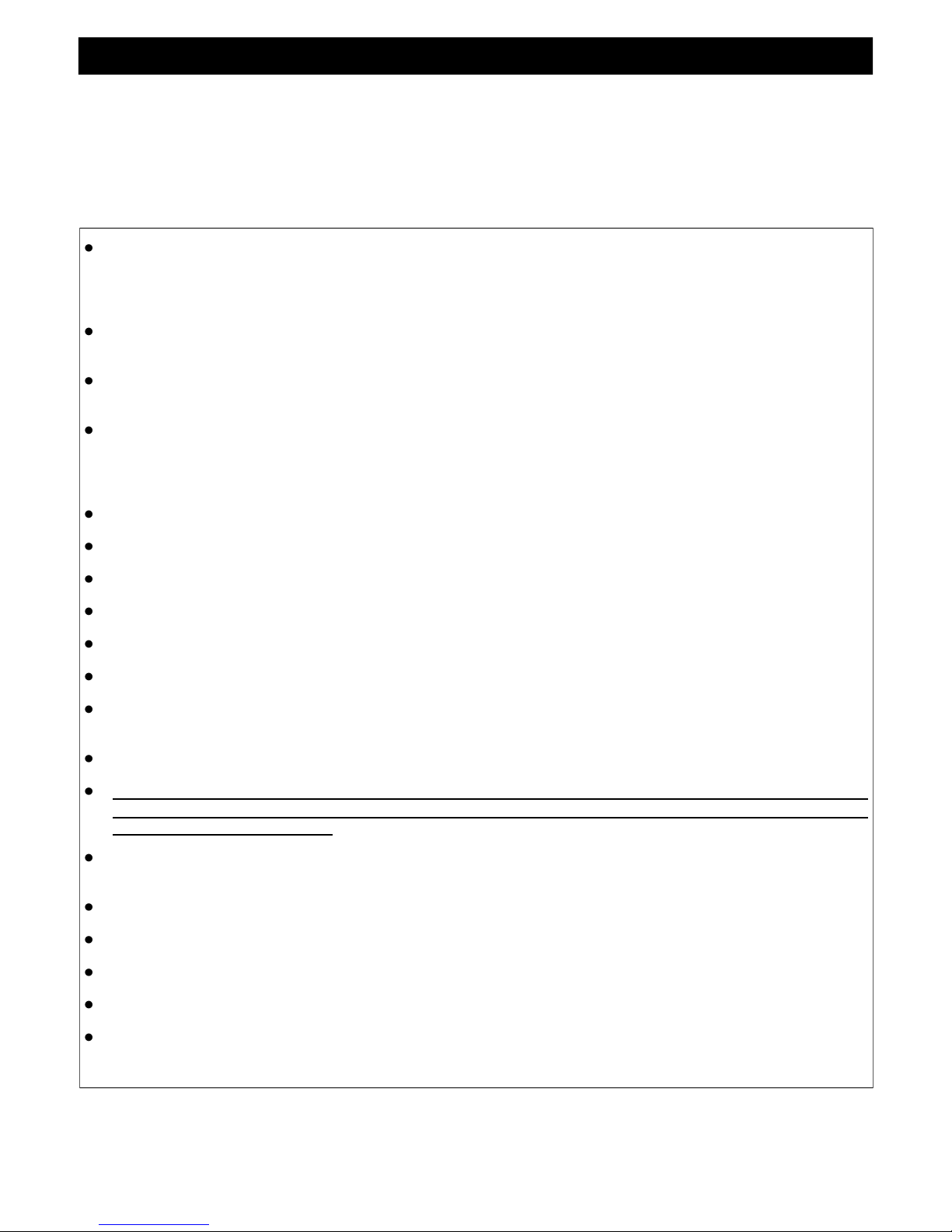
SAFETY INFORMATION
This fireplace has been tested by OMNI-Test Laboratories, Portland, Oregon and complies with:
ANSI Z21.88-2009/CSA 2.33-2009, “Standard for Vented Gas Fireplace Heaters”.
CAN/CGA 2.17-M91 (R2009), “Gas-Fired Appliances for Use at High Altitudes”.
CAN/CSA P.4.1-09, “Testing Method for Measuring Annual Efficiency”.
This installation must conform with local codes, or in the absence of local codes, with the National Fuel Gas Code, ANSI Z223.1/NFPA 54,
or the Natural Gas and Propane Installation Code, CSA B149.1
Installation and repair should be done only by a qualified service person. The appliance should be inspected by a
qualified service person before use. Annual inspection by a qualified service person is required to maintain warranty.
More frequent cleaning may be required due to excessive lint from carpeting, bedding materials, etc. It is imperative
th at co ntro l co mpa rtme nts , bu rners an d ci rculati on a ir passa gew ays o f th e ap plia nce be ke pt c lea n.
If this appliance is installed directly on carpeting, tile or other combustible material other than wood flooring, the
appliance shall be installed on a metal or wood panel extending the full width and depth of the appliance.
Children and adults should be alerted to the hazards of high surface temperatures and should stay away to avoid burns
or clothing ignition.
Young children should be carefully supervised when they are in the same room as the appliance. Toddlers, young
children and others may be susceptible to accidental contact burns. A physical barrier is recommended if there are at
risk individuals in the house. To restrict access to a fireplace or stove, install an adjustable safety gate to keep toddlers,
young children and other at risk individuals out of the room and away from hot surfaces.
Clothing or other flammable material should not be placed on or near the appliance.
Adequate accessibility clearances for servicing and proper operation must be maintained.
This appliance must not share or be connected to a chimney flue serving any other appliance.
Keep area around the appliance clear of combustible materials, gasoline and other flammable vapor and liquids.
The flow of combustion and ventilation air must not be obstructed.
Due to high temperatures the appliance should be located out of traffic and away from furniture and draperies.
The glass front or any part removed for servicing the appliance must be replaced prior to operating the appliance.
Work should be done by a qualified service technician.
Clean glass only when cool and only with non-abrasive cleansers.
WARNING: DO NOT OPERATE APPLIANCE WITH THE GLASS/FRAME ASSEMBLY REMOVED, CRACKED
OR BROKEN. REPLACEMENT OF THE GLASS SHOULD ONLY BE PERFORMED BY A LICENSED OR
QUALIFIED SERVICE PERSON.
The glass assembly, Part #JOR-057T, shall only be replaced as a complete unit, as supplied by Hussong Mfg. Co., Inc.
DO NOT SUBSTITUTE MATERIALS.
Do not strike or slam glass assembly.
Any safety screen or guard removed for servicing the appliance must be replaced prior to operating the appliance.
Under no circumstances should any solid fuel (wood, coal, paper or cardboard etc.) be used in this appliance.
Keep burner and control compartment clean.
Do not use this fireplace if any part has been under water. Immediately call a qualified service technician to inspect this
appliance and to replace any part of the control system and any gas control which has been under water.
3

COMMONWEALTH OF MASSACHUSETTS REQUIREMENTS
NOTE The following requirements reference various Massachusetts and national codes not contained in this manual.
For all sidewall horizontally vented gas fueled equipment installed in every dwelling, building or structure used in whole or in part for residential purposes,
including those owned or operated by the Commonwealth and where the side wall exhaust vent termination is less than (7) feet above finished grade in the
area of the venting, including but not limited to decks and porches, the following requirements shall be satisfied:
INSTALLATION OF CARBON MONOXIDE DETECTORS
At time of installation of side wall horizontally vented gas fueled equipment, the installing plumber or gas-fitter shall observe that a hard wired carbon
monoxide detector with an alarm and battery back-up is installed on the floor level where the gas equipment is to be installed. In addition, the installing
plumber or gas-fitter shall observe that a battery operated or hard wired carbon monoxide detector is installed on each additional level of the dwelling,
building or structure served by the side wall horizontal vented gas fueled equipment. It shall be the responsibility of the property owner to secure the services
of qualified licensed professionals for the installation of hard wired carbon monoxide detectors .
In the event that the side wall horizontally vented gas fueled equipment is installed in a crawl space or attic, the hard wired carbon monoxide detector with
alarm and battery back-up may be installed on the next adjacent floor level.
In the event that the requirements of this subdivision can not be met at the time of completion of installation, the owner shall have a period of thirty (30) days
to comply with the above requirements; provided, however, that during said thirty (30) day period, a battery operated carbon monoxide detector with an
alarm shall be installed.
APPROVED CARBON MONOXIDE DETECTORS
Each carbon monoxide detector as required in accordance with the above provisions shall comply with NFPA 720 and be ANSI/UL 2034 listed and IAS
certified.
SIGNAGE
A metal or plastic identification plate shall be permanently mounted to the exterior of the building at a minimum of eight (8 ) feet above grade directly in line
with the exhaust vent terminal for the horizontally vented gas fueled heating appliance or equipment. The sign shall read, in print no less the one-half inch
(1/2) in size, “GAS VENT DIRECTLY BELOW. KEEP CLEAR OF ALL OBSTRUCTIONS”.
INSPECTION
The state or local gas inspector of the side wall horizontally vented gas fueled equipment shall not approve the installation unless, upon inspection, the
inspector observes carbon monoxide detect ors and signage installed in accordance with the provisions of 248 CMR 5.08 (2) (a) 1 through 4.
EXEMPTIONS
The following equipment is exempt from 248 CMR 5.08 (2) (a) 1 through 4:The equipment listed in Chapter 10 entitled “Equipment Not Required To Be
Vented” in the most current edition of NFPA 54 as adopted by the Board; and Product Approved side wall horizontally vented gas fueled equipment installed
in a room or structure separate from the dwelling, building or structure used in whole or in part for residential purposes.
MANUFACTURER REQUIREMENTS - GAS EQUIPMENT VENTING SYSTEM PROVIDED
When the manufacturer of Product Approved side wall horizontally vented gas equipment provides a venting system design or venting system components
with the equipment, the instructions provided by the manufacturer for installation of the equipment and the venting system shall include:
Detailed instructions for the installation of the venting system design or the venting system components; and
A complete parts list for the venting system design or venting system.
MANUFACTURER REQUIREMENTS - GAS EQUIPMENT VENTING SYSTEM NOT PROVIDED
When the manufacturer of Product Approved side wall horizontally vented gas equipment does not provide the parts for venting the flue gases, but identifies
“special venting systems”, the following requirements shall be satisfied by the manufacturer:
The referenced “special venting systems” instructions shall be included with the appliance or equipment installation instructions and;
The “special venting systems” shall be Product Approved by the Board, and the instructions for that system shall include a parts list and detailed
installation instructions.
A copy of all installation instructions for all Product Approved side wall horizontally vented gas fueled equipment, all venting instructions, all parts lists for
venting instructions, and/or all venting design instructions shall remain with the appliance or equipmen t at the completion o f the installation.
4
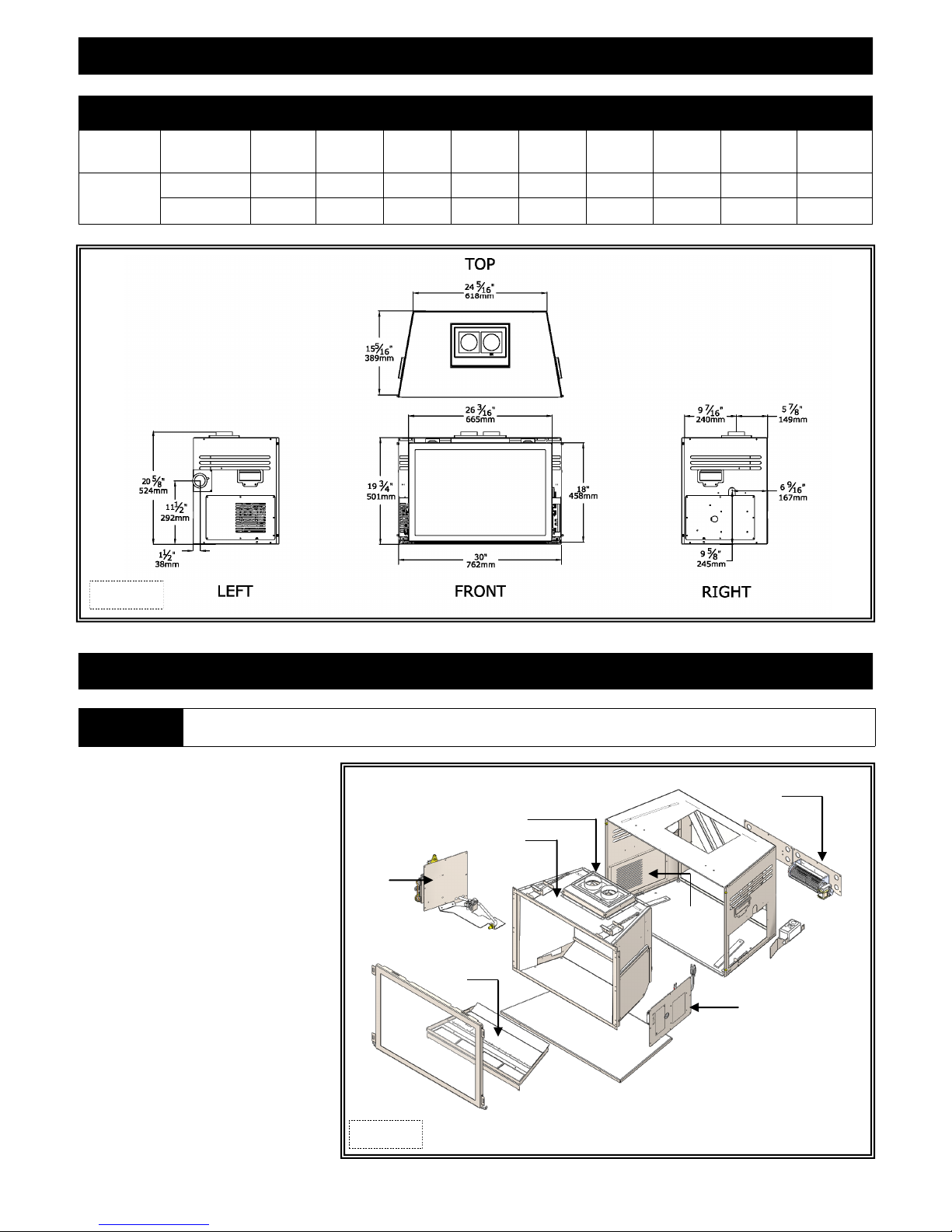
FIREPLACE
DIMENSIONS
SPECIFICATIONS
FIREPLACE DIMENSIONS
DESCRIPTION Height Width Back Width Depth Height to Air
INCHES 19-3/4 30 24-5/16 15-1/2 20-5/8 6-9/16 1-1/2 9-7/16 5-7/8
MILLIMETERS 501 762 618 394 524 167 38 240 149
Chute Top
Back to Elec.
Access
Back to Gas
Line Access
Front to Vent
Center
Back to Vent
Center
Figure 5a
WARNING
Failure to position components in accordance with these diagrams or failure to use only parts specifically approved for use with
MPS-30 may result in property damage or personal injury.
1. Fireplace insert
2. Air chute
3. Module panel assembly
4. Valve access panel
5. Control board assembly
6. Burner
7. Glass frame assembly
8. Firebox liner
9. Black glass media kit (not shown)
10. Fan kit
11. Floor Protector Kit (sold separately).
PARTS DIAGRAM
10
2
1
5
4
8
6
3
7
11
Figure 5b
5
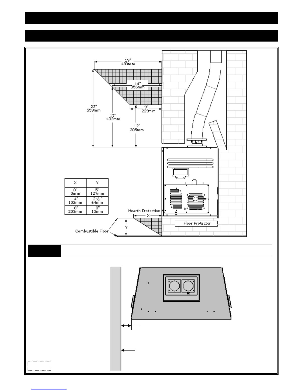
SPECIFICATIONS
MINIMUM CLEARANCES TO COMBUSTIBLES
WARNING
Figure 6a
Hearth protection chart above shows minimum clearances from top surface of combustible flooring (carpeting, tile, etc.).
These clearances must be maintained.
3”
(76mm)
Combustible
Material
6
SPECIFICATIONS
ADDITIONAL COMPONENTS REQUIRED
Vent System: Part #816-CL: For use with minimum 6” x 8” I.D. masonry or 7” I.D. Class A metal chimneys - Includes 12ft. (3.66m)
compressed, expandable to 35ft. (10.67m) co-linear 3” x 3” flexible chimney, and termination cap.
Other approved venting: ICC, Selkirk, American Metals, Simpson Dura-Vent, RLH, Security, Metal Fab
Approved caps listed on page 10.
Shrouds: Standard shrouds are available for this insert and will fit most applications. Custom shrouds may be ordered on a non -returnable
basis. When ordering a custom shroud, please specify the existing fireplace front opening height and width.
or
Blank Shrouds: Blank shrouds are available for on-site custom fit applications and are sized to the opening after the insert has been
installed. The interior perimeter is properly sized to fit onto the insert. The outer perimeter must be cut, formed and
finished (painted).
To be used with;
Screen Front: Screen Fronts in various finishes.
PLACEMENT CLEARANCE REQUIREMENTS
This fireplace must be installed on a level surface capable of supporting the fireplace and venting.
This fireplace insert is to be installed into a solid fuel masonry or factory built non-combustible fireplace that has been installed in
accordance with the National, Provincial, State and local building codes.
Due to high surface temperatures, fireplace should be located out of traffic and away from furniture and draperies.
This fireplace may be installed in a bedroom.
Please be aware of the large amount of heat this fireplace will produce when determining a location.
EXISTING FIREPLACE SPECIFICATIONS
THIS INSERT IS APPROVED FOR INSTALLATION IN MASONRY AND FACTORY-BUILT SOLID FUEL BURNING FIREPLACES.
EXISTING FIREPLACE REQUIREMENTS
The existing fireplace & chimney must be clean and in good working order and constructed of non-combustible materials.
A gas line must be able to be installed to the insert.
Provisions made to provide electrical power for operation.
Any chimney clean-outs must fit properly.
Existing Chimney must be comprised of one of the following: Factory built solid fuel chimney: 7” minimum inside diameter.
Masonry chimney: 6" x 8" minimum inside diameter.
Existing Chimney Height: Minimum: 10ft. (3.05m)
Maximum: 35ft. (10.67m)
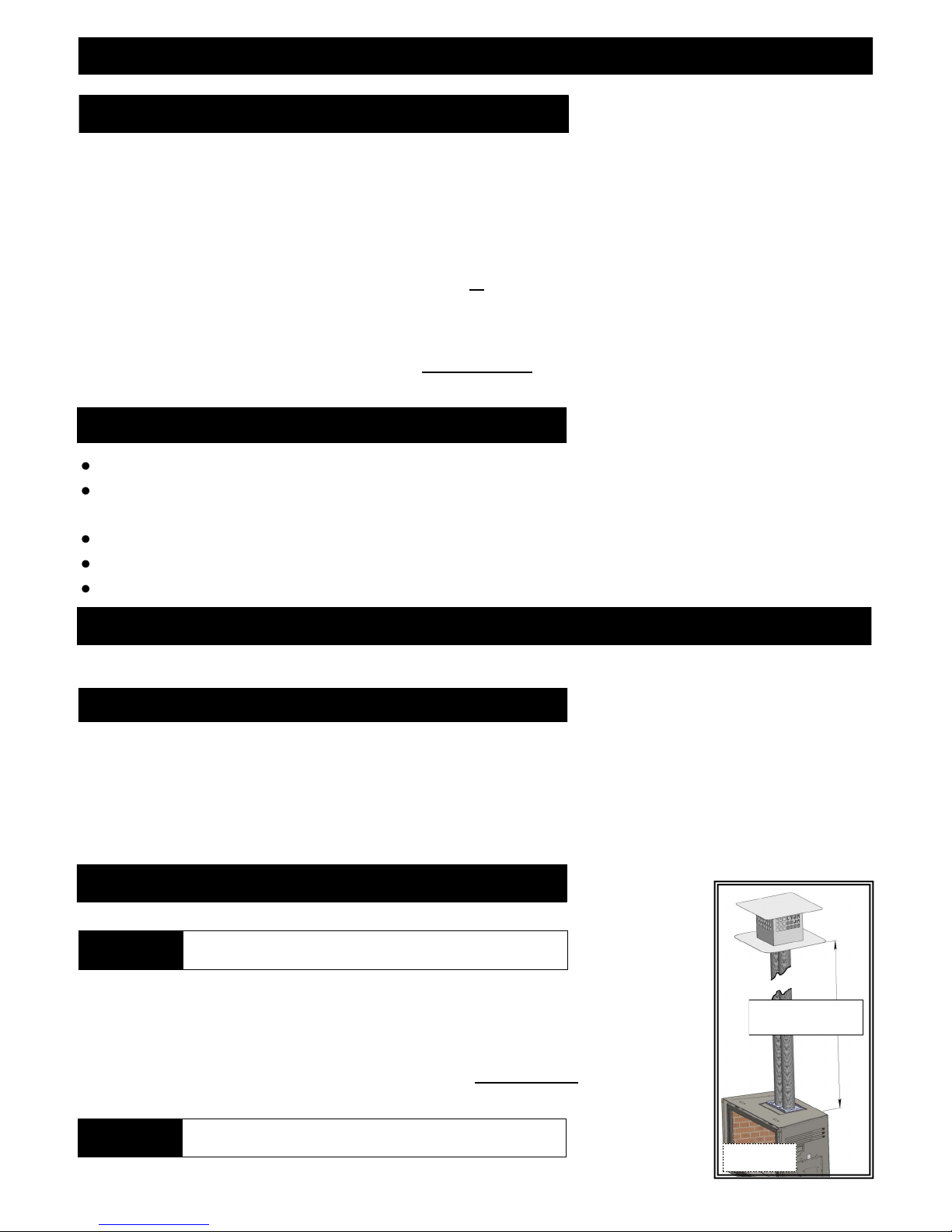
DETERMINE LENGTH OF EXISTING CHIMNEY
1. Remove and discard existing chimney cap.
NOTE
2. Position one person at fireplace and another person at top of chimney.
Measure from fireplace base to top of chimney.
Subtract 19-3/4” (501mm) (height of insert).
This is the total length of co-linear flexible aluminum you will require.
MEASUREMENT FROM FIREPLACE BASE TO TOP OF CHIMNEY:_________________
LESS 19-3/4" (501mm) (HEIGHT OF INSERT): -19-3/4" (501mm)_
TOTAL CHIMNEY LENGTH REQUIRED: _________________
It is helpful to have two people complete next ste p to determine
chimney height.
MIN. 10ft. (3.05m)
MAX. 35ft. (10.67m)
CAUTION
This appliance must not be connected to or joined with any other
chimney flue serving another appliance.
Figure 7a
7
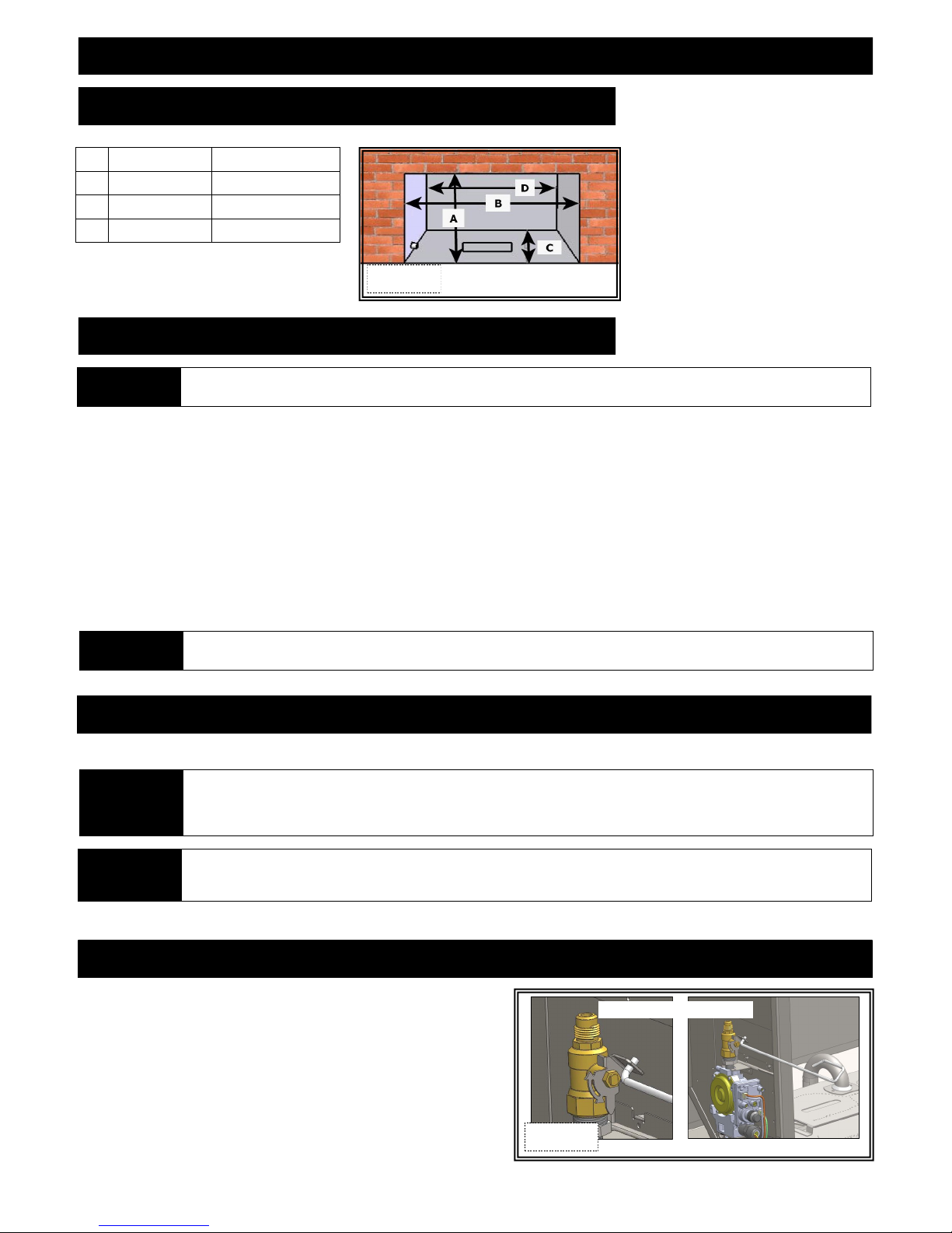
PREPARE EXISTING FIREPLACE
EXISTING FIREPLACE MINIMUM OPENING REQUIREMENTS
A Height 20-5/8” (524mm)
B Front Width 30-5/16” (770mm)
C Depth 16” (406mm)
D Back Width 24-5/16” (618mm)
Figure 8a
PREPARE EXISTING FIREPLACE
ATTENTION Any removed parts must be capable of reinstallation if this insert is ever removed (removal of rivets or screws is acceptable).
Any removed parts must be capable of reinstallation if this insert is ever removed (removal of rivets or screws is acceptable ).
The refractory, glass doors, screen rails, screen mesh and log grates may be removed from existing fireplace before installing this gas
fireplace insert. Any smoke shelves, shields and baffles may be removed if attached by mechanical fasteners. If necessary, remove firebrick
to obtain at least minimum opening requirements.
The fireplace flue damper can be fully blocked open or removed for installation of this gas fireplace insert. Remove existing chimney cap.
Clean chimney and inside of fireplace to prevent creosote smell from entering the home.
Cutting of any sheet metal parts is prohibited, except the metal floor. If metal floor is removed, the insert must be placed directly on metal
base of metal fireplace. If using this method, Kozy Heat Floor Protector Kit (#JOR-FLP) must be used, and leveling bolts (provided)
must be installed in insert bottom, providing 1/2” (13mm) required clearance to floor protector.
Mechanically attach ‘THIS UNIT HAS BEEN MODIFIED’ label at bottom of existing firebox so it will be visible if this gas fireplace
insert is removed.
CAUTION Trim panels or surrounds must not seal ventilation openings in existing fireplace that this appliance is install ed in.
ELECTRICAL WIRING
This fireplace insert comes complete with a fan kit already installed.
Electrical wiring must be installed by a licensed electrician.
ATTENTION
WARNING
This appliance must be electrically wired and grounded in accordance with local codes or, in the absence of local codes, with
Nation Electric Code, ANSI/NFPA 70-latest edition, or the Canadian Electric Code, CSA C22.1
This appliance is equipped with a three-prong (grounding) plug for protection against shock hazard and should be plugged
directly into a properly grounded three -prong recep tacle. Do not cut or remove grounding prong fro m this plug.
Do not allow excess cord to touch fireplace.
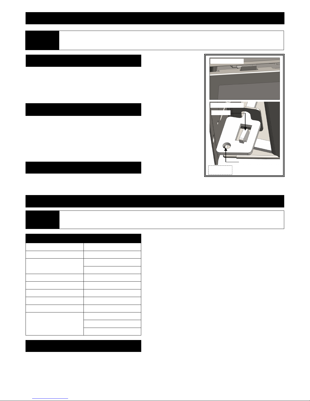
MANUAL SHUT-OFF VALVE
The manual shut-off valve is located on left side wall of insert. Use glass
latch attachment tool (included in components packet) to open or close
valve.
SHOWN IN OPEN POSITION
Figure 8b
8
GAS LINE CONNECTION
GAS CONVERSION
IMPORTANT This fireplace is NAT gas ready. If converting to LP gas, do so now before installing into existing fireplace.
ATTENTION
CAUTION
NOTE
IMPORTANT
NATURAL GAS LP GAS
The conversion shall be carried out in accordance with the requirements of the provincial authorities having jurisdiction and in
accordance with the requirements of the ANSI Z223.1 installation code.
Installation of the gas line must only be done by a qualified person in accordance with local building codes, if any.
If not, follow ANSI 223.1.
Commonwealth of Massachusetts: Installation must be done by a licensed plumber of gas fitter.
A listed (and Commonwealth of Massachusetts approved) 1/2” (13mm) T-handle manual shut-off valve and flexible gas
connector (included) are connected to the 1/2” (13mm) control valve inlet. If substituting for these components, please consult
local codes for compliance.
This fireplace is equipped with a 3/8”(10mm) x 18” (457mm) long flexible gas connector and manual shut-off valve. The gas
line should be run to the point of connection where the shut-off valve and flexible gas line will connect.
The appliance and its individual shutoff valve must be disconnected from the gas supply piping system during any pressure
testing of that system at pressures in excess of ½ psi (3.5 kPa).
The appliance must be isolated from the gas supply piping system by closing its individual manual shut-off valve during any
pressure testing of the gas line at test pressures equal to or less than ½ psi (3.5 kPa).
For high altitude installations, consult the local gas distributor or the authority having jurisdiction for proper rating methods.
The efficiency rating of this appliance is a product of thermal efficiency rating determined under continuous operating
conditions and was determined independently of any installed system.
MINIMUM INLET GAS PRESSURE 5” WC (1.25 kPa) (7” WC (1.74 kPa) (recommended) 11” WC (2.74 kPa) (recommended)
MAXIMUM INLET GAS PRESSURE 10.5” WC (2.62 kPa) 13” WC (3.24 kPa)
Run gas line through left gas line access hole at back corners of insert. For your convenience, access hole may be removed an d rotated to
accommodate side gas line installation.
NOTE
If installing this gas fireplace insert into a factory-built fireplace and the factory-built fireplace has no access hole provided, an
access hole of 1-1/2"(38mm) or less may be drilled through the lower sides or bottom of the firebox in a proper workmanship
like manner. This access hole must be plugged with non-combustible insulation after the gas supply line has been installed.
9
WARNING
GLASS FRAME / SCREEN FRONT
DO NOT OPERATE THIS FIREPLACE WITH GLASS REMOVED, CRACKED OR BROKEN. REPLACEMENT OF GLASS FRAME
ASSEMBLY, #JOR-057T SHOULD BE DONE BY A LICENSED OR QUALIFIED SERVICE PERSON.
DO NOT REMOVE THESE COMPONENTS WHEN HOT!
REMOVE GLASS FRAME ASSEMBLY
A. Locate spring-loaded latches securing glass frame assembly at bottom of firebox.
B. Using glass latch tool (included in components packet) pull bottom latches out and up to
release glass frame assembly latch tabs.
C. Lift glass frame assembly up off tabs located at top of firebox.
INSTALL GLASS FRAME ASSEMBLY
A. Make certain bottom latches are pushed down to allow for easier installation.
B. Align slots at top of glass frame assembly over tabs at top of firebox while lowering
bottom of glass frame assembly into position.
C. Using glass latch tool, pull latches out and down over latch tabs to secure glass frame
assembly bottom.
SCREEN FRONT (sold separately)
To install: Align tabs on back of frame with slots on insert, set into position.
To remove: Lift frame up and out of slots.
INSTALLATION
Upper tab (1 ea. side)
Lower latch (1 ea. side)
Latch tab
Figure 10a
Insert glass latch tool here
All steps as outlined in ‘PREPARE EXISTING FIREPLACE’ must be completed before continuing with this installation.
ATTENTION
Follow instructions from vent pipe manufacturer as well as venting requirements as outlined in this installation manual.
APPROVED VENTING
MANUFACTURER APPROVED CAPS
Kozy Heat 816-CL Vent System
ICC TM-IVT
Selkirk 4DT-VC
American Metals 4DVC
Simpson Dura-Vent 46DVA-VCH
Security 3PDVCV
Metal Fab 4DVT
TM-SVT
HS-C33U99 RLH
HS-C33F1313
HS-CD3333-1313
COMBUSTION AIR VENTING OPTIONS
OPTION 1: FULL CONNECTION: Combustion air intake pipe is run entire chimney length and connected to termination cap.
OPTION 2: STUB VENTING: Combustion air intake pipe is extended a minimum of 4ft. (1.22m) past damper opening into
existing chimney. It is not connected to termination cap.
10
INSTALLATION
AIR DUCT REMOVAL
1. Remove refractory panels (secured at top with clips - 1 ea. side).
2. Remove (3) screws securing baffle to firebox back wall. Pull baffle forward and down to remove.
3. Remove access plate (secured with (2) screws) from firebox ceiling.
4. Locate and remove nuts securing air duct top to firebox; 2 nuts reached through access holes, 2 inside air duct.
5. Remove air duct top.
Access Plate
Figure 11a
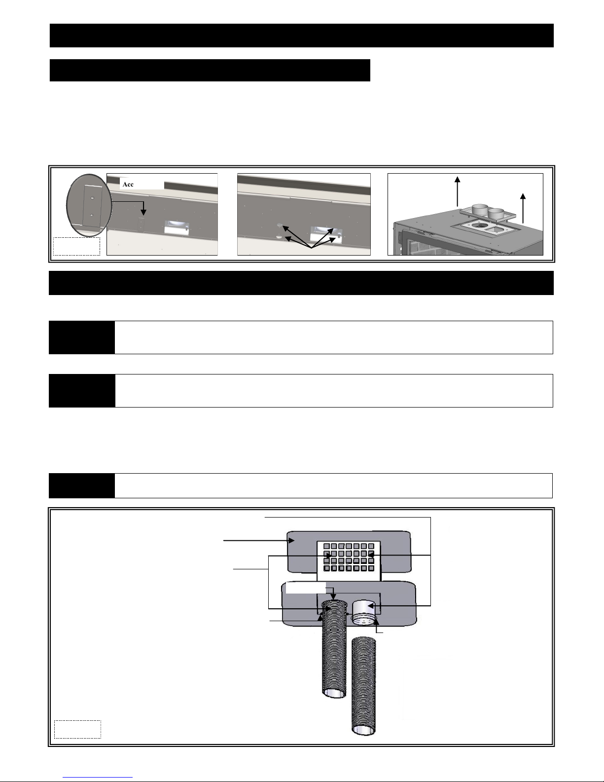
KOZY HEAT #816-CL CO-LINEAR VENT SYSTEM
The co-linear pipes included in this vent system are designed to extend up to 35ft. (10.67m)
NOTE
IDENTIFICATION: Exhaust Pipe: red marking.
Proper operation of this insert requires exhaust and combustion air pipes be connected to correct collars on termination kit and
insert air duct.
A. Carefully extend exhaust and combustion air intake pipes to equal total chimney length required.
NOTE
If using stub method for combustion air pipe, extending it is not necessary. Determine length needed from air duct on insert (4ft.
(1.22m) minimum) to above damper opening in existing chimney. Remove excess combustion air pipe from end without a collar.
Continue with Step B. #2 below.
Full Connection method: Slide intake pipe (end without collar) over termination cap collar. Secure with 3 self-tapping screws (provided).
B. Place bead of sealant around inner edge at end of exhaust pipe (without collar / red marking) and slide onto corresponding collar on
termination cap (collar with label). Secure with 3 self-tapping screws (provided). Apply additional sealant around joint to ensure a
proper seal.
IMPORTANT
EXHAUST COLLAR ON FIREPLACE AIR DUCT IS ON RIGHT SIDE. INSTALL TERMINATION CAP WITH EXHAUST COLLAR ON
RIGHT SIDE.
EXHAUST COLLAR
(Extends through middle divider plate)
TERMINATION CAP
INTAKE COLLAR
(Extends through bottom plate)
SEALANT
SHEET METAL SCREWS (3 TOTAL)
Figure 11b
Your vent cap may look slightly different than one shown.
SEALANT
11
 Loading...