

kozy heat JORDAN-34S Installation And Operation Manual
HUSSONG MANUFACTURING CO., INC.
JORDAN-34S
OMNI-Test
Laboratories, Inc.
Model #JOR-34S
Direct Vent Gas Fireplace Insert
Installation and
Operation Manual
WARNING:
FIRE OR EXPLOSION HAZARD
Failure to follow safety warnings exactly
could result in serious injury, death, or
property damage.
ͷ Do not store or use gasoline or other
ammable vapors and liquids in the
vicinity of this or any other appliance.
ͷ WHAT TO DO IF YOU SMELL GAS
• Do not try to light any appliance.
• Do not touch any electrical switch; do
not use any phone in your building.
• Leave the building immediately.
• Immediately call your gas supplier from
a neighbor’s phone. Follow the gas
supplier’s instructions.
• If you cannot reach your gas supplier,
call the re department.
ͷ Installation and service must be performed
by a qualied installer, service agency or
the gas supplier.
Tested &
Listed By
C US
Portland
Oregon USA
This appliance may be installed in
an aftermarket, permanently located,
manufactured home (USA only) or mobile
home, where not prohibited by local codes.
This appliance is only for use with the type
of gas indicated on the rating plate. This
appliance is not convertible for use with
other gases, unless a certied kit is used.
INSTALLER: Leave this manual with the appliance.
CONSUMER: Retain this manual for future reference.
Hussong Mfg. Co., Inc. • JOR-34S Report No.: 0216GN034S • Rev. 01, February 2015
English and French installation manuals are
available through your local dealer. Visit our
website www.kozyheat.com or scan the QR
code for our mobile app.

Read this manual before installation or operating this appliance.
Please retain this owner’s manual for future reference.
CONGRATULATIONS!
We welcome you as a new owner of a Kozy Heat gas replace. Kozy Heat products are designed with superior components
and materials, and assembled by trained craftsmen who take pride in their work. To ensure you receive a quality product, the
burner and valve assembly are 100 percent test-red, and the complete replace is thoroughly inspected before packaging. Our
commitment to quality and customer satisfaction has remained the same for over 30 years. We offer a complete line of gas and
wood replaces, along with stylish accessories to complement any decor. Adding a replace is one of the best ways to increase
the value of your home, and we are proud to offer a network of dealers throughout the country to help make your experience
everything you imagine. We pride ourselves in being dedicated not only to functionality and reliability, but also customer
safety. We offer our continual support and guidance to help you achieve the maximum benet and enjoyment from your Kozy
Heat gas replace.
Jim Hussong
President
Homeowner Reference Information
We recommend you record the following information:
Model Name: ___________________________________________
Serial Number: __________________________________________
Dealership Purchased from: _______________________________
Notes: _____________________________________________________________________________________________________________
____________________________________________________________________________________________________________________
____________________________________________________________________________________________________________________
____________________________________________________________________________________________________________________
____________________________________________________________________________________________________________________
Date purchased/installed: _________________________________
Location of fireplace: _____________________________________
Dealer phone: ___________________________________________
Dudley Hussong
Board Chairman
HOMEOWNER REFERENCE 3


TABLE OF CONTENTS
TABLE OF CONTENTS ................................................................... 5
1.0 INTRODUCTION ......................................................................7
1.1 Appliance Certification .................................................................. 7
1.2 Requirements for the Commonwealth of Massachusetts ......7
2.0 SPECIFICATIONS .................................................................... 8
2.1 Appliance Components ................................................................8
2.2 Heating Specifications .................................................................. 8
2.3 Appliance Dimensions ..................................................................9
2.4 Part Assembly Overview ...............................................................10
2.5 Safety Barriers ................................................................................11
3.0 EXISTING FIREPLACE REQUIREMENTS ............................. 12
3.1 Appliance Placement Considerations ........................................ 12
3.2 Existing Fireplace Specifications ............................................... 12
4.0 TERMINATION LOCATION .....................................................13
4.1 Vent Termination Clearances .......................................................13
5.0 INSTALLATION PREPARATION .............................................14
5.1 Inspect and Clean Existing Chimney ......................................... 14
5.2 Flue Damper ...................................................................................14
5.3 Gas Line...........................................................................................14
5.4 Electrical Wiring ............................................................................. 14
5.5 Fireplace Conversion ................................................................... 14
6.0 INSTALLATION ........................................................................15
6.1 Kozy Heat #816-CL Co-Linear Vent System ............................15
6.2 Remove Air Duct ........................................................................... 16
6.3 Run Vent System ............................................................................16
6.4 Connect Vent Pipe to Air Duct ....................................................17
6.5 Place and Secure Appliance ....................................................... 17
7.0 GAS LINE CONNECTION ........................................................ 18
7.1 Gas Conversion (sold separately) ..............................................18
7.2 Gas Line Installation ...................................................................... 18
8.0 FACING AND FINISHING ........................................................ 19
8.1 Clearances to Combustibles ....................................................... 19
8.2 Shroud Installation ......................................................................... 20
8.3 Safety Barrier Installation .............................................................20
9.0 GAS FIREPLACE INSERT SETUP .......................................... 21
9.1 Glass Assembly .............................................................................. 21
9.2 Light Kit ............................................................................................ 21
9.3 #J34-500 Log Set Installation ..................................................... 22
9.4 Control Board Removal and Installation .................................... 23
10.0 ELECTRICAL INFORMATION ............................................... 24
10.1 Electrical Specifications ............................................................. 24
10.2 Wiring Requirements ...................................................................24
11.0 OPERATING INSTRUCTIONS .............................................. 25
11.1 Setup Proflame 2 IFC Module ................................................... 26
11.2 Initialize the Control System ......................................................26
11.3 Reset the System for Manual Operation .................................26
11.4 Automatic Safety Restart ............................................................26
11.5 Backup Battery Operation ........................................................ 26
11.6 IFC Module Ignition Sequence ................................................. 27
11.7 Additional Diagnostic Information ............................................. 27
11.8 Remote Control Operation ........................................................ 28
12.0 ADJUSTMENT ....................................................................... 31
12.1 Pressure Testing ..........................................................................31
12.2 Flame Appearance Adjustment ................................................. 32
13.0 TROUBLESHOOTING ........................................................... 33
14.0 MAINTENANCE ..................................................................... 35
14.1 Burner and Pilot System ............................................................ 35
14.2 Fan ..................................................................................................35
14.3 Vent System ..................................................................................35
14.4 Glass Assembly ........................................................................... 35
15.0 REPLACEMENT PARTS LIST ............................................... 36
LIMITED WARRANTY ..................................................................... 37
LIFETIME WARRANTY ...................................................................39
TABLE OF CONTENTS 5


1.0 INTRODUCTION
1.1 Appliance Certification
Laboratory: OMNI-Test Laboratories in Portland, Oregon
Standards:
• ANSI Z21.88-2014/CSA 2.33-2014, Vented Gas Fireplace
Heaters
• CGA 2.17-M91 (R2009) , Gas-Fired Appliances for Use at High
Altitudes
• CSA P.4.1-2009, Testing Method for Measuring Annual
Fireplace Efficiency
This installation must conform with local codes, or in the absence
of local codes, with the
NFPA 54, or the
B149.1.
Natural Gas and Propane Installation Code
National Fuel Gas Code
, ANSI Z223.1/
, CSA
1.2 Requirements for the
Commonwealth of Massachusetts
The following requirements reference various Massachusetts and
national codes not contained in this manual.
For all sidewall horizontally vented gas fueled equipment installed
in every dwelling, building or structure used in whole or in part
for residential purposes, including those owned or operated
by the Commonwealth and where the side wall exhaust vent
termination is less than (7) feet above finished grade in the area
of the venting, including but not limited to decks and porches, the
following requirements shall be satisfied:
1.2.1 Installation of Carbon
Monoxide Detectors
At time of installation of side wall horizontally vented gas fueled
equipment, the installing plumber or gas-fitter shall observe that
a hard wired carbon monoxide detector with an alarm and battery
back-up is installed on the floor level where the gas equipment is
to be installed. In addition, the installing plumber or gas-fitter shall
observe that a battery operated or hard wired carbon monoxide
detector is installed on each additional level of the dwelling,
building or structure served by the side wall horizontal vented gas
fueled equipment. It shall be the responsibility of the property
owner to secure the services of qualified licensed professionals
for the installation of hard wired carbon monoxide detectors.
In the event that the side wall horizontally vented gas fueled
equipment is installed in a crawl space or attic, the hard wired
carbon monoxide detector with alarm and battery back-up may
be installed on the next adjacent floor level. In the event that
the requirements of this subdivision can not be met at the time
of completion of installation, the owner shall have a period of
thirty (30) days to comply with the above requirements; provided,
however, that during said thirty (30) day period, a battery
operated carbon monoxide detector with an alarm shall be
installed.
for the horizontally vented gas fueled heating appliance or
equipment. The sign shall read, in print no less the one-half inch
(½) in size, “GAS VENT DIRECTLY BELOW. KEEP CLEAR OF ALL
OBSTRUCTIONS”.
1.2.4 Inspection
The state or local gas inspector of the side wall horizontally
vented gas fueled equipment shall not approve the installation
unless, upon inspection, the inspector observes carbon monoxide
detectors and signage installed in accordance with the provisions
of 248 CMR 5.08 (2) (a) 1 through 4.
1.2.5 Exemptions
The following equipment is exempt from 248 CMR 5.08 (2) (a) 1
through 4: The equipment listed in Chapter 10 entitled “Equipment
Not Required To Be Vented” in the most current edition of NFPA
54 as adopted by the Board; and Product Approved side wall
horizontally vented gas fueled equipment installed in a room or
structure separate from the dwelling, building or structure used in
whole or in part for residential purposes.
1.2.6 Manufacturer Requirements
1.2.6.1 Gas Equipment Venting System Provided
When the manufacturer of Product Approved side wall horizontally
vented gas equipment provides a venting system design or
venting system components with the equipment, the instructions
provided by the manufacturer for installation of the equipment and
the venting system shall include:
• Detailed instructions for the installation of the venting system
design or the venting system components; and
• A complete parts list for the venting system design or venting
system.
1.2.6.2 Gas Equipment Venting
System NOT Provided
When the manufacturer of Product Approved side wall horizontally
vented gas equipment does not provide the parts for venting the
flue gases, but identifies “special venting systems”, the following
requirements shall be satisfied by the manufacturer:
• The referenced “special venting systems” instructions shall
be included with the appliance or equipment installation
instructions and;
• The “special venting systems” shall be Product Approved by
the Board, and the instructions for that system shall include a
parts list and detailed installation instructions.
A copy of all installation instructions for all Product Approved
side wall horizontally vented gas fueled equipment, all venting
instructions, all parts lists for venting instructions, and/or all
venting design instructions shall remain with the appliance or
equipment at the completion of the installation.
1.2.2 Approved Carbon Monoxide Detectors
Each carbon monoxide detector as required in accordance with
the above provisions shall comply with NFPA 720 and be ANSI/
UL 2034 listed and IAS certified.
1.2.3 Signage
A metal or plastic identification plate shall be permanently
mounted to the exterior of the building at a minimum of eight (8)
feet above grade directly in line with the exhaust vent terminal
INTRODUCTION 7
2.0 SPECIFICATIONS
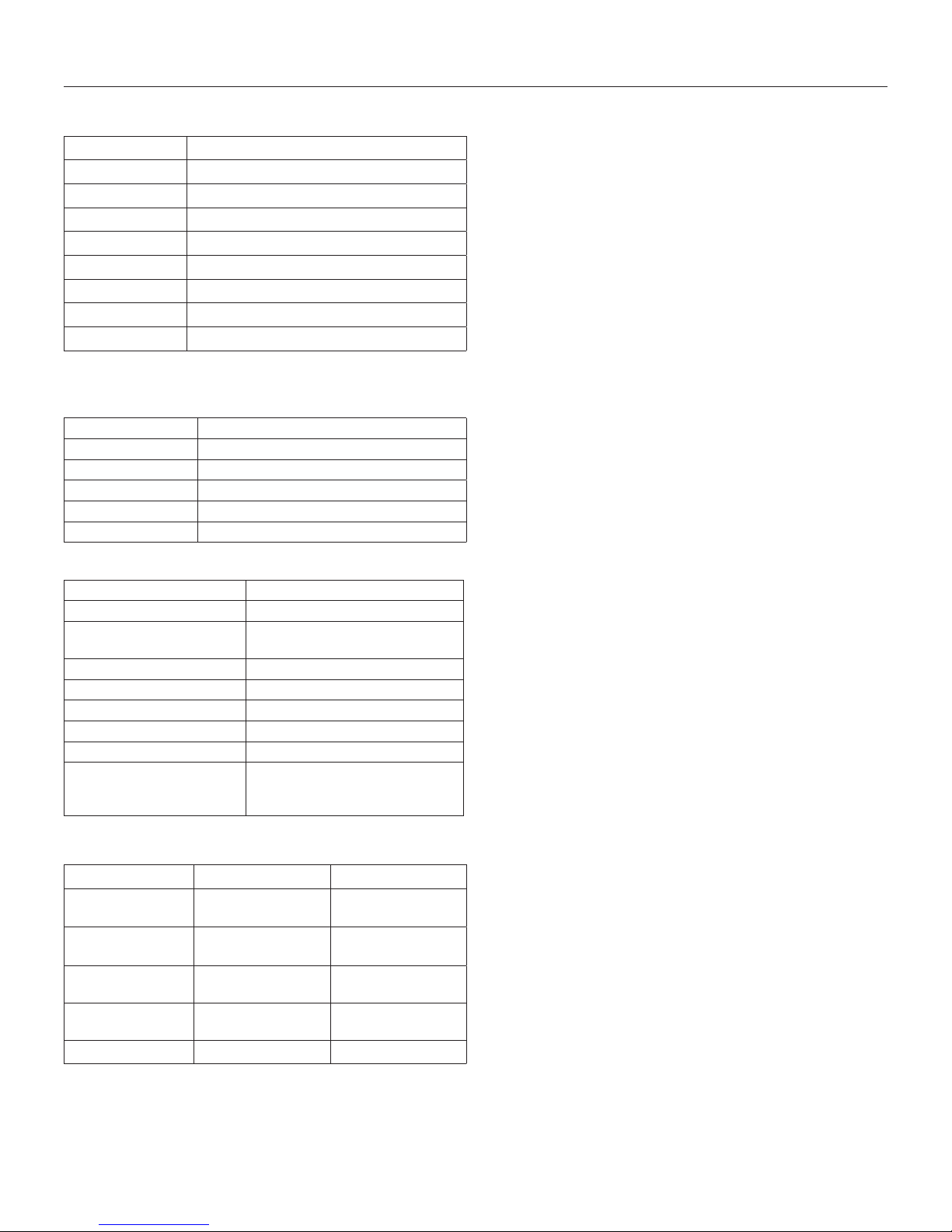
2.1 Appliance Components
Part Number Description
J34-160 Control Board Assembly
700-203 Manual Gas Shut-off Valve
J34-500 Log Package
JXL-057T Glass Assembly
JOR-028 Fan Kit (1)-75 CFM
J34-LKT Light Kit
700-508 Remote Control
JOR-GLT Glass Latch Tool
2.1.1 Additional Components Required
2.1.1.1 Shrouds
Part Number Description
JXL-27040 27” x 40” shroud (1 piece)
JXL-30042 30” x 42” shroud (1 piece)
JXL-33046 33” x 46” shroud (1 piece)
JXL-CUS Custom shroud (1 piece)
JXL-ACUS Custom Arched shroud (1 piece)
2.1.1.2 Approved Vent Systems
Vent Manufacturer Approved Caps
Kozy Heat #816-CL Co-linear Vent System
ICC TMT-IVT
TM- SVT
Selkirk 4DT-VC
American Metals (Amerivent) 4DVC
Simpson Dura-Vent 46DVA-VCH
Security 3PDVCV
Metal Fab 4DVT
RLH HS- C33U99
HS- C33F1313
HS- CD3333-1313
2.2.1 Altitude Adjustment
This appliance may be installed at higher altitudes. Please refer
to National Fuel Gas Code ANSI Z223.1/NFPA 54, CSA-B149.1
Natural Gas and Propane Installation Code, local authorities,
or codes having jurisdiction in you area regarding derate
guidelines.
2.2.1.1 US Installations
Refer to the American Gas Association guidelines for the gas
designed appliances derating method. For elevations above 2,000
ft (610 m) , input ratings are to be reduced by 4% for each 1,000 ft
(305 m) above sea level.
2.2.1.2 Canadian Installations
When the appliance is installed at elevations above 4,500 ft (1,372
m), the certified high altitude rating shall be reduced at the rate of
4% for each additional 1,000 ft (305 m).
2.2 Heating Specifications
Natural Gas LP Gas
Maximum
Input Rating
Minimum
Input Rating
Manifold Pressure
(High)
Manifold Pressure
(Low)
Orifice Size (DMS) FRONT: 55 BACK: 37 FRONT: 65 BACK: 51
8 SPECIFICATIONS
39,000 Btu/h
(11.43 kW)
17,000 Btu/h
(4.98 kW)
3.8” WC (.95 kPa) 11” WC (2.74 kPa)
1.1” WC (.27 kPa) 2.9” WC (.72 kPa)
39,000 Btu/h
(11.43 kW)
17,000 Btu/h
(4.98 kW)
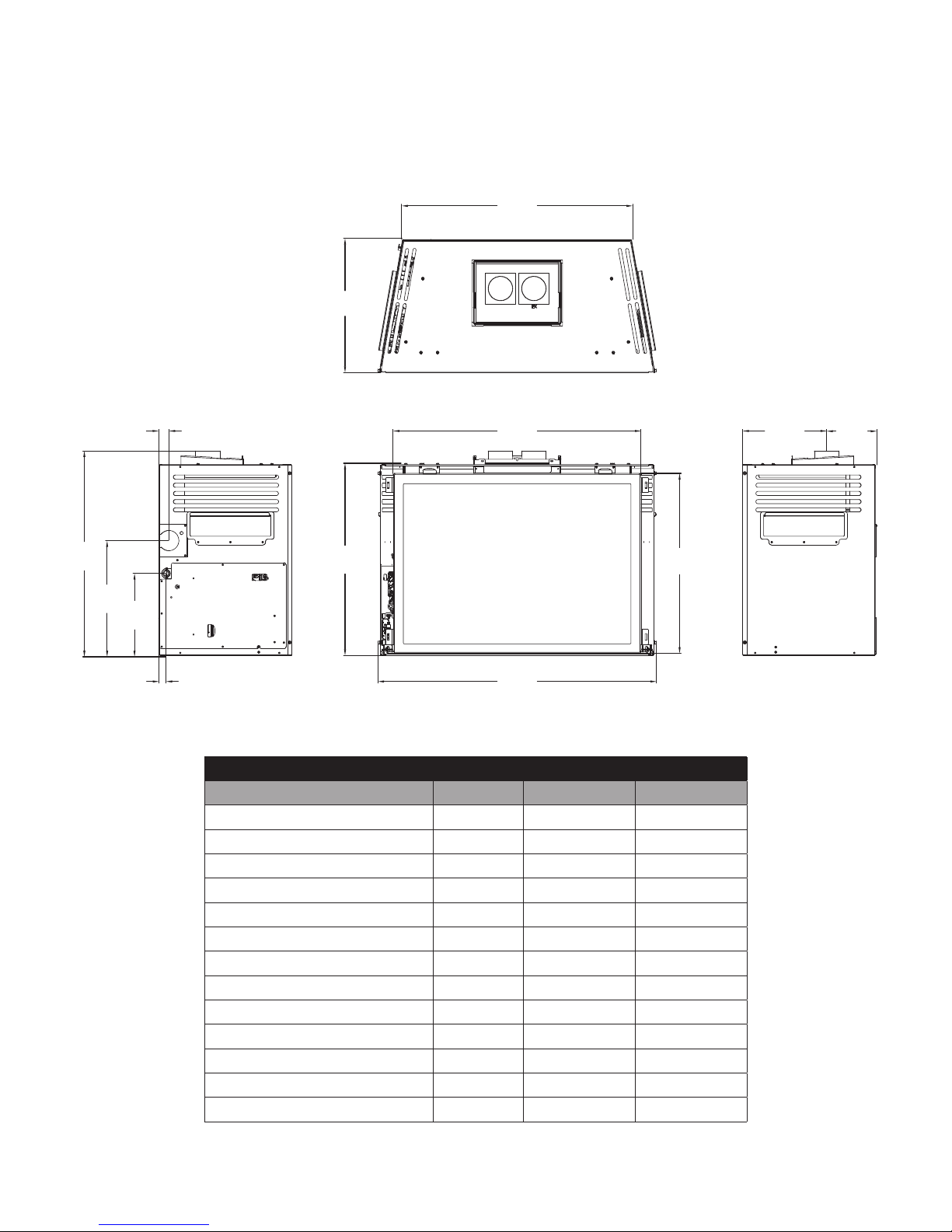
2.3 Appliance Dimensions
TOP
E
F
G
H
I
A
D
L
M
B
J
K
C
LEFT FRONT RIGHT
Table 2.1, JOR-34S Physical Dimensions
DESCRIPTION LOCATION INCHES MILLIMETERS
Height A 23-3/8 594
Opening Height B 22-1/4 565
Width C 34 864
Opening Width D 30-1/4 768
Back Width E 28-3/16 716
Depth F 16-3/8 416
Height to Air Duct Top G 25-1/8 638
Unit Bottom to Gas Line Access H 14-1/8 360
Back to Gas Line Access I 1-1/4 32
Unit Bottom to Electrical Access J 10-3/16 258
Back to Electrical Access K 7/8 22
Front to Vent Center L 10-1/4 260
Back to Vent Center M 6-1/8 156
SPECIFICATIONS 9
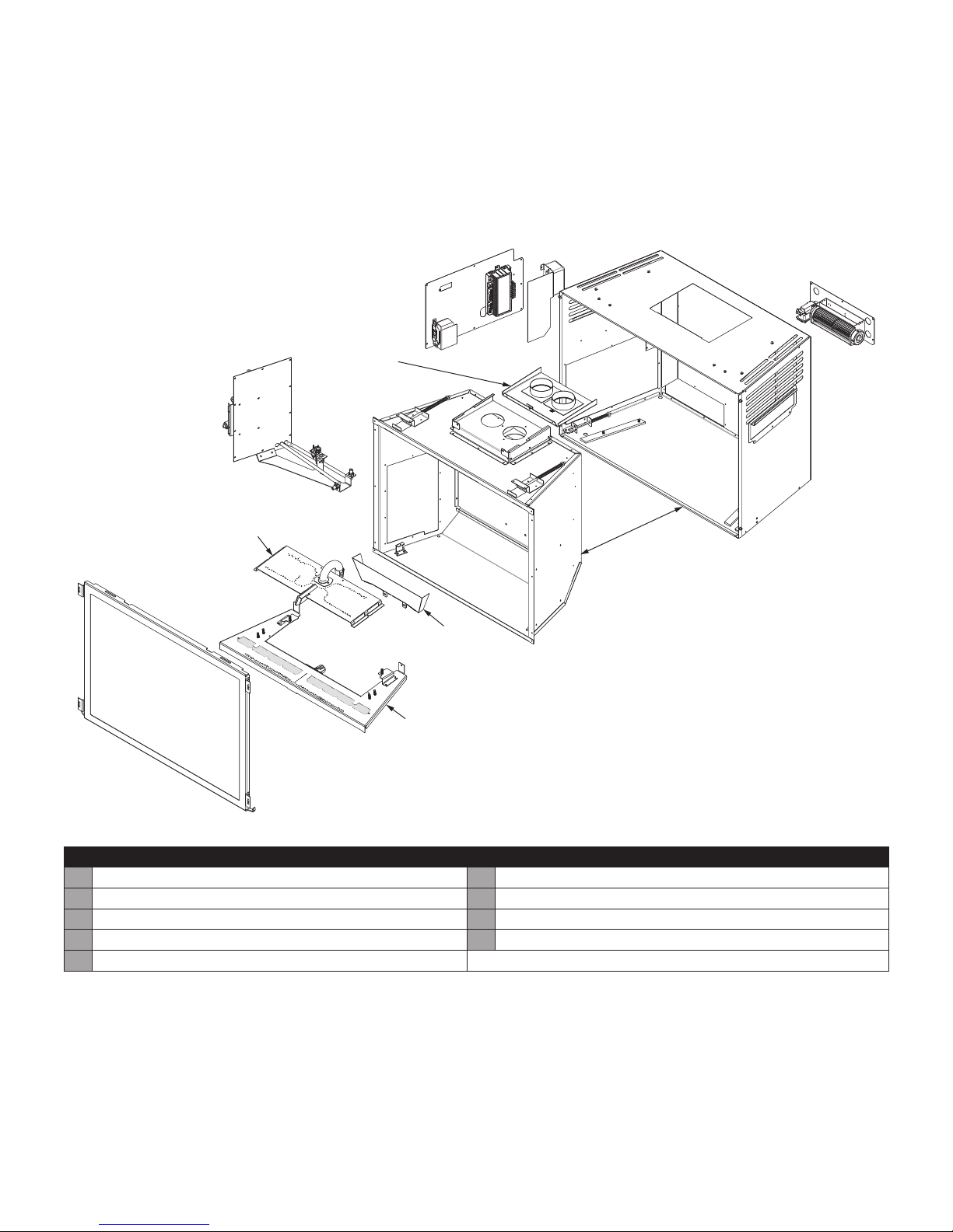
2.4 Part Assembly Overview
WARNING: Failure to position these parts in accordance with
these diagrams, or failure to use only specified approved parts
with this appliance, may result in property damage or personal
injury.
I
C
B
G
F
D
E
H
Table 2.2, Field-Assembled Parts
A Fireplace insert F Back burner assembly
B Module panel assembly G Fan kit
C Control board assembly H Glass frame assembly
D Light Kit I Air duct
E Front burner assembly
A
10 SPECIFICATIONS
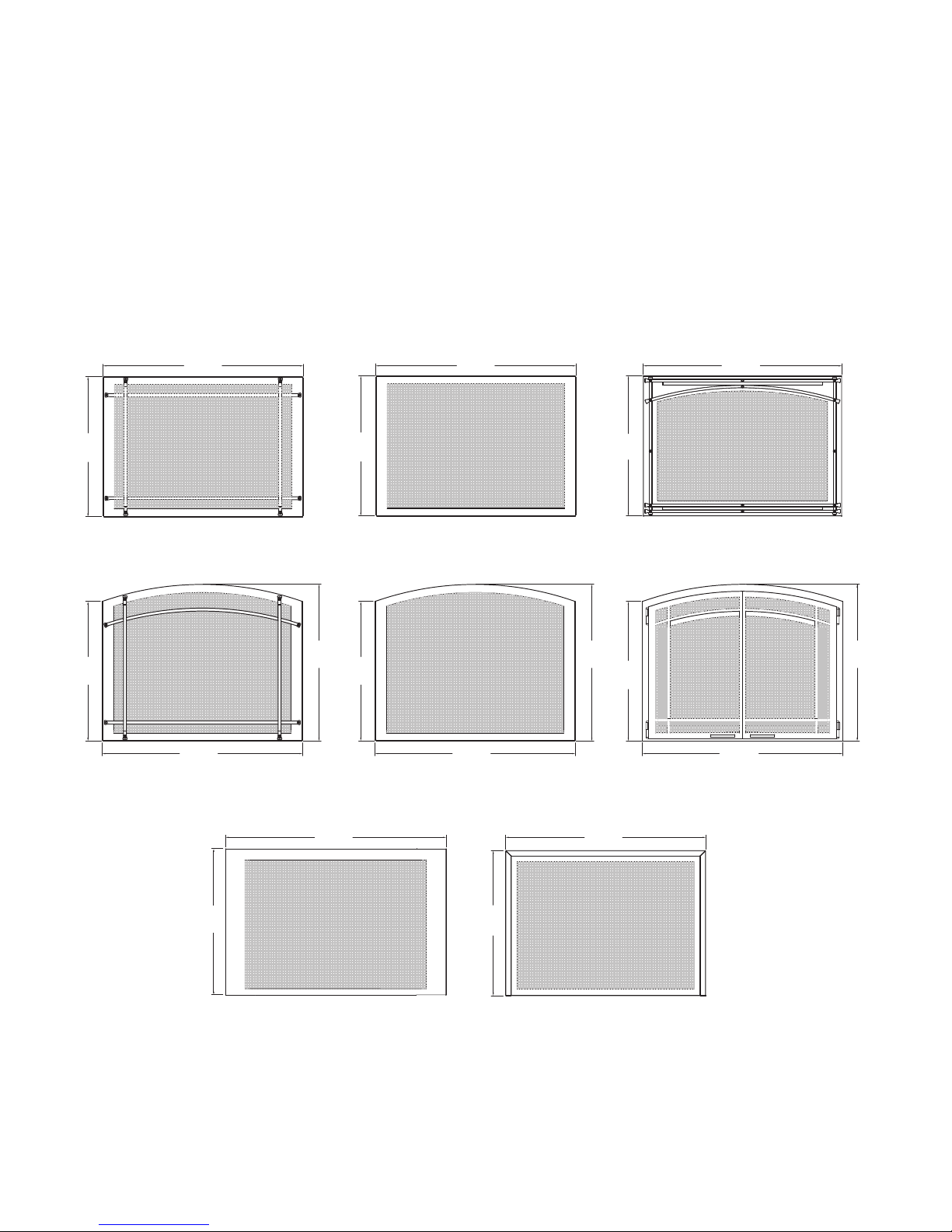
2.5 Safety Barriers
WARNING: A barrier designed to reduce the risk of burns from
the hot viewing glass is provided with this appliance and shall
be installed for the protection of children and other at-risk
individuals.
If the barrier becomes damaged, the barrier shall be replaced
with Hussong Mfg.’s barriers for this appliance. Only doors
certified with the appliance shall be used.
Please refer to Section 8.3 Safety Barrier Installation on page
20 for installation instructions.
23⁄”
(609mm)
23
⁄”
(606mm)
¼”
34
(870mm)
⁄”
23
(609mm)
34
¼”
(870mm)
24”
(609mm)
34”
(863mm)
J34-PSF J34-RSF J34A-MSF
¾”
26
34
¼”
(870mm)
(680mm)
⁄”
23
(606mm)
34
¼”
(870mm)
J34A-PSF J34A-SF
26
¾”
(680mm)
23
⁄”
(606mm)
¼”
34
(870mm)
J34A-FPDSF
¾”
26
(680mm)
(959mm)
25”
(635mm)
J34-CXF J34-BSF
37
¾”
⁄”
24
(631mm)
34
¼”
(870mm)
SPECIFICATIONS 11
3.0 EXISTING FIREPLACE REQUIREMENTS
3.1 Appliance Placement
Considerations
WARNING: Due to high surface temperatures, the fireplace
insert should be located out of traffic and away from furniture
and draperies.
• This fireplace must be installed on a level surface capable of
supporting the fireplace insert and venting.
• This fireplace insert may be installed in a bedroom.
• Please be aware of the large amount of heat this fireplace
insert will produce when determining a location.
3.2 Existing Fireplace Specifications
• If necessary, remove firebrick to obtain at least the minimum
opening requirements.
• Cutting any sheet-metal parts of the fireplace, in which the
gas fireplace insert is to be installed, is prohibited.
• If the metal floor is removed, the insert must be placed
directly on the metal base of metal fireplace using the Kozy
Heat Floor Protector Kit (#JXL-FLP). The provided leveling
bolts with the kit must be installed at the bottom corners of
the gas insert for the required 1/4” (6mm) air space to the
floor protector. See Section 3.2.1.
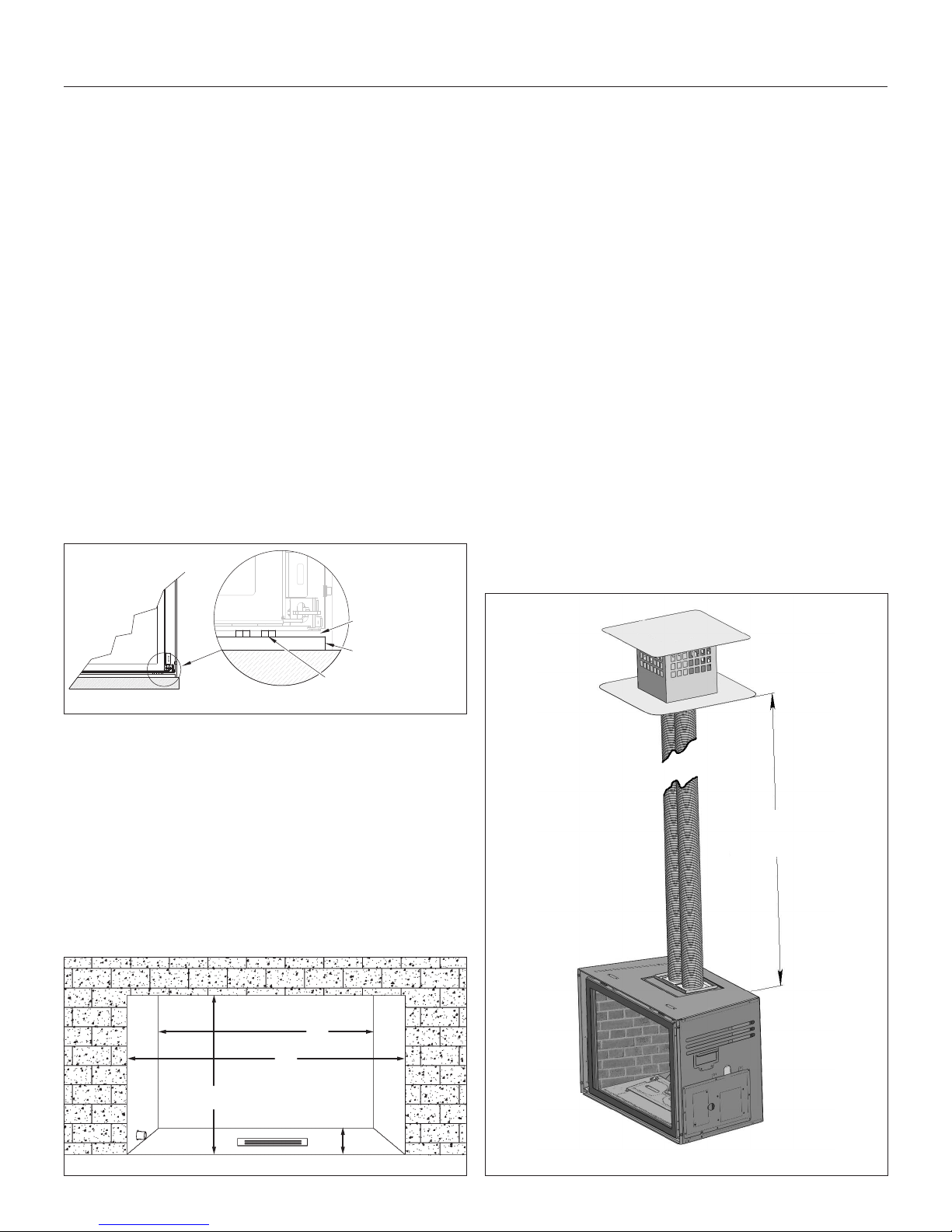
3.2.2 Chimney Specifications
WARNING: Any chimney clean-outs must fit properly.
This fireplace insert is to be installed into a solid fuel masonry
or factory built non-combustible fireplace that has been
installed in accordance with the national, provincial, state, and
local building codes.
The existing chimney must be comprised of one of the
following:
• Factory-built solid fuel chimney: 7 in (178mm) minimum
inside diameter
• Masonry chimney: 6 in x 8 in (152mm x 203mm) minimum
inside diameter
Existing chimney height:
• Minimum: 10 ft (3.05 m) Maximum: 50 ft (15.24 m)
3.2.2.1 Determine Length of Existing Chimney
1. Remove and discard existing chimney cap.
2. It is helpful to have two people complete this step. Position
one person at the fireplace and another person at the top of
the chimney.
3. Measure from the fireplace base to the top of the chimney.
4. Subtract the height of the insert from the previous
measurement. This is the total length of the co-linear flexible
aluminum pipe required for your installation.
¼ in (6mm) AIR SPACE
FLOOR PROTECTOR
(#JXL-FLP)
LEVELING BOLT
Figure 3.1, #JXL-FLP
3.2.1 Existing Fireplace Opening
Minimum Requirements
(A) Height............................................................. 24½ in (622 mm)*
(B) Front Width .........................................................34 in (846 mm)
(C) Depth ............................................................... 16⅜ in (416 mm)
(D) Back Width .................................................... 28⁄ in (716 mm)
*If installing the #JXL-FLP, add ¾ in (19 mm) (total dimension
of floor protector and airspace) to height to maintain minimum
existing fireplace height opening requirements.
D
B
MIN: 10 ft (3.05m)
MAX: 50 ft (15.24m)
A
Figure 3.2, Existing Opening Guide
12 EXISTING FIREPLACE REQUIREMENTS
C
Figure 3.3, Min/Max Chimney Length
 Loading...