

kozy heat Jackson 911, Jackson 911-IPI, Jackson 911-RAD, Jackson XL 911XL, Jackson XL 911XL-RAD Installation And Operation Manual
...
INSTALLATION AND OPERATION MANUAL
INSTALLER: LEAVE THIS MANUAL WITH THE APPLIANCE.
CONSUMER: RETAIN THIS MANUAL FOR FUTURE REFERENCE.
DO NOT
DISCARD
DIRECT VENT FIREPLACE INSERT
WARNING: This product must be installed by a licensed plumber or gas fitter when installed in the
commonwealth of Massachusetts.
This appliance may be installed in an aftermarket permanently located, manufactured (mobile) home, where not prohibited by local codes.
A manufactured home (USA only) or mobile home OEM installation must conform with the Manufactured Home Construction and Safety
Standard, Title 24 CFR, Part 3280, or when such a standard is not applicable, the Standard for Manufactured Home Installations, ANSI/NCSBCS A225.1,
or Standard for Gas Equipped Recreational Vehicles and Mobile Housing, CSA Z240.4
WARNING: If the information in these instructions are not followed exactly, a fire or explosion may
result, causing property damage, personal injury or loss of life.
◙ Do not store or use gasoline or other flammable vapors and liquids in the vicinity of this or any other
appliance.
IF YOU SMELL GAS:
◙ Do not light any appliance.
◙ Do not touch any electrical switch: do not use any phone in your building.
◙ Immediately call gas supplier from a neighbors phone. Follow the gas supplier instructions.
◙ If you cannot reach your gas supplier, call the fire department.
◙ Installation and service must be performed by a qualified installer, service agency or the gas supplier.
This appliance is only for use with the type (s) of gas indicated on the rating plate.
A conversion kit is supplied with the appliance.
WARNING
HOT GLASS WILL CAUSE BURNS.
DO NOT TOUCH GLASS UNTIL COOLED.
NEVER ALLOW CHILDREN TO TOUCH GLASS.
Report Number: 216-F-22-4
www.kozyheat.com
JAN 2011
911-R18
INTRODUCTION
Read this manual before installing or operating this appliance.
Please retain this owner‘s manual for future reference.
CONGRATULATIONS!
We welcome you as a new owner of a Kozy Heat gas fireplace. Kozy Heat products are
designed with superior components and materials and assembled by trained craftsmen who
take pride in their work. The burner and valve assembly are 100% test-fired and the complete
fireplace is thoroughly inspected before packaging to ensure that you receive a quality product.
Our commitment to quality and customer satisfaction have remained the same for over 30
years. We offer a complete line of gas and wood fireplaces, unique cabinets and stylish
accessories to compliment any décor. Adding a fireplace is one of the best ways to increase the
value of your home and we are proud to offer a network of dealers throughout the country to
help make your experience everything you imagine. We pride ourselves in being dedicated to
not only function and reliability, but customer safety as well. We offer our continual support
and guidance to help you achieve the maximum benefit and enjoyment from your Kozy Heat
gas fireplace.
Jim Hussong Dudley Hussong
President Board Chairman
Homeowner Reference Information
We recommend that you record the following information about your fireplace.
Model Name:______________________________ Date purchased/installed:___________________________
Serial Number:____________________________ Location on fireplace:_______________________________
Dealership purchased from:__________________ Dealer Phone:____________________________________
Notes:_____________________________________________________________________________________
__________________________________________________________________________________________
__________________________________________________________________________________________
PAGE 1
TABLE OF CONTENTS
INTRODUCTION
Introduction and Homeowner Reference Information 1
TABLE OF CONTENTS
Table of Contents 2
SAFETY INFORMATION
Safety Information 3
FEATURES
Features 4
COMMONWEALTH OF MASSACHUSETTS INFORMATION
Commonwealth of Massachusetts Information 5
SPECIFICATIONS
Fireplace Insert Dimensions 6
Clearances 6
Components List 7
Additional Components Required 7
Placement Clearance Requirements 7
EXISTING FIREPLACE SPECIFICATIONS
Existing Fireplace Requirements 8
Existing Fireplace Minimum Opening Requirements 8
PREPARE EXISTING FIREPLACE
Prepare Existing Fireplace 9
GLASS FRAME ASSEMBLY
Remove Glass Frame Assembly 9
Install Glass Frame Assembly 9
FAN DIRECT WIRE INSTALLATION
Fan Direct Wire Installation 10
THERMOSTAT / WALL SWITCH / REMOTE
Thermostat / Wall Switch / Remote 11
GAS LINE CONNECTION
Gas Line Connection 12
INSTALLATION
Approved Venting 13
Air Duct Removal 13
911-MSP Masonry Side Panel Installation (Optional) 13
Restrictor 13
VENTING INSTALLATION
Kozy Heat #815-CL Co-Linear Vent System 14-16
Kozy Heat #815-CA Co-Axial Vent System 17-18
COMPLETE FAN WIRING INSTALLATION
Complete Fan Wiring Installation 19
CONTROL BOARD
Control Board Installation 20
Control Board Removal 20
ZC SHROUD ASSEMBLY AND INSTALLATION
ZC Shroud Assembly and Installation 21
MASONRY SHROUD ASSEMBLY AND INSTALLATION
Masonry Shroud Assembly and Installation 22-23
LOG SET INSTALLATION
Log Set Installation 24
911 / 911-RAD OPERATING INSTRUCTIONS
911 / 911-RAD Valve and Pilot Assembly Components 25
911 / 911-RAD Lighting and Shutdown 26-28
911 / 911-RAD Pressure Testing 29
911-IPI OPERATING INSTRUCTIONS
911-IPI Wiring Schematics 30
911-IPI Valve and Pilot Assembly Components 31
911-IPI Control Module Components 32
911-IPI Remote Control Components 33
911-IPI Information 34
911-IPI Remote Control Operation 35-37
911-IPI Lighting and Shutdown Instructions 38-39
911-IPI Pressure Testing 40
911-IPI Error Codes 41
FINALIZING THE INSTALLATION
Flame Appearance 42
Venturi Adjustment 42
Restrictor Usage / Troubleshooting / Installation / Modification 43
Seasonal Heat Dump 44
MAINTENANCE
Maintenance 45
TROUBLESHOOTING
911 / 911-RAD Troubleshooting 46-48
911-IPI Troubleshooting 49-50
CONVERSION KIT INSTRUCTIONS
911 / 911-RAD Conversion Kit Instructions 51
911-IPI Conversion Kit Instructions 52-53
REPLACEMENT PARTS LIST
Replacement Parts List 54
WARRANTY
Warranty 55-56
PAGE 2

SAFETY INFORMATION
This fireplace has been tested to and complies with ANSI Z21.88a-2007·CSA 2.33a-2007·M02 “VENTED GAS FIREPLACE HEATERS” by OMNI-
Test Laboratories, Portland, OR. Installation must conform with local building codes or in the absence of local building codes, with the National
Fuel Gas Code, ANSIZ223.1/NFPA 54 - Current Edition, or the Natural or Propane Installation Code, CSAB149.1
Installation and repair should be done only by a qualified service person. The appliance should be inspected by a
qualified service person before use. Annual inspection by a qualified service person is required to maintain warranty.
More frequent cleaning may be required due to excessive lint from carpeting, bedding materials, etc. It is imperative
that control compartments, burners and circulation air passageways of the appliance be kept clean.
This fireplace insert is to be installed into a solid fuel masonry or factory built non-combustible fireplace that has
been installed in accordance with the National, Provincial, State and local building codes.
Children and adults should be alerted to the hazards of high surface temperatures and should stay away to avoid
burns or clothing ignition.
Young children should be carefully supervised when they are in the same room as the appliance. Toddlers, young
children and others susceptible to accidental contact burns. A physical barrier is recommended if there are at risk
individuals in the house. To restrict access to a fireplace or stove, install an adjustable safety gate to keep toddlers,
young children and other at risk individuals out of the room and away from hot surfaces.
Clothing or other flammable material should not be place on or near the appliance.
Adequate accessibility clearances for servicing and proper operation must be maintained.
This appliance must not share or be connected to a chimney flue serving any other appliance.
Keep area around the appliance clear of combustible materials, gasoline and other flammable vapor and liquids.
The flow of combustion and ventilation air must not be obstructed.
Due to high temperatures the appliance should be located out of traffic and away from furniture and draperies.
The glass front or any part removed for servicing the appliance must be replaced prior to operating the appliance.
Work should be done by a qualified service technician.
Clean glass only when cool and only with non-abrasive cleansers.
Do not operate this appliance with the glass/frame assembly removed, cracked or broken. The glass assembly, Part
#700-08T, shall only be replaced as a complete unit, as supplied by Hussong Mfg. Co., Inc. Replacement of glass
assembly must only be performed by a licensed or qualified service person. DO NOT SUBSTITUTE MATERIALS.
Do not strike or slam glass assembly.
Any safety screen or guard removed for servicing the appliance must be replaced prior to operating the appliance.
Under no circumstances should any solid fuel (wood, coal, paper or cardboard etc.) be used in this appliance.
Keep burner and control compartment clean.
Do not use this fireplace if any part has been under water. Immediately call a qualified service technician to inspect
this appliance and to replace any part of the control system and any gas control which has been under water.
Do not operate without refractory brick lining installed.
PAGE 3
FEATURES
STANDARD FEATURES
High efficiency
High quality lifetime glass
12‖ x 27‖ (305 mm x 686 mm)
Quick latch glass frame assembly
Co-linear vent system - (manifold)
Seasonal heat dump baffle
Patented burner system and log design
High - Low regulator
Automatic fan kit (2) - 75 CFM**
Refractory brick lining
Minnesota Energy Code compliant to 50 pascals
*Standard on RAD models
**Standard on 911 and 911-IPI models
***Standard on 911-IPI models
****Standard on 911 and 911-RAD models
SAFETY FEATURES
Each unit factory tested!
Tested by OMNI - Test Laboratories
Sealed combustion chamber
Standing pilot ignition****
Intermittent or Standing pilot ignition***
30-second delay pilot****
Flame sensing system (safety shutoff)***
Automatic pressure relief glass system
Requires no electricity to operate** (excluding fan )
Battery back-up in the event of power failure***
(excluding fan)
Bedroom and mobile home approved
Canadian approved
*Standard on 911 models
**Standard on 911 and 911-IPI models
***Standard on 911-IPI models
****Standard on 911 and 911-RAD models
OPTIONAL FEATURES
Co-linear vent system
Co-axial vent system
Grills – several styles/finishes
Arched valance brass or chrome trim
Rectangular valance (replaces arched valance)
Valance Screen
On-off remote control or thermostatic remote control
Wall mount thermostat / wireless wall mount thermostat
Decorative screen doors in various styles and finishes
Decorative full door shrouds in various styles and finishes
3 pc. or 4 pc. shrouds (Masonry or ZC style)
Shroud trim in various finishes
Custom shrouds (Masonry or ZC style)
Clean face frames in various colors
Masonry side panels
Automatic fan kit**
*Standard on RAD models
**Standard on 911 and 911-IPI models
***Standard on 911-IPI models
****Standard on 911 and 911-RAD models
WEIGHT
Fireplace Weight (as packaged for shipment)
119 lbs. (53.98 kg)
PAGE 4

COMMONWEALTH OF MASSACHUSETTS REQUIREMENTS
NOTE: The following requirements reference various Massachusetts and national codes not contained in this manual.
For all sidewall horizontally vented gas fueled equipment installed in every dwelling, building or structure used in whole or in part for residential purposes,
including those owned or operated by the Commonwealth and where the side wall exhaust vent termination is less than (7) feet above finished grade in the
area of the venting, including but not limited to decks and porches, the following requirements shall be satisfied:
INSTALLATION OF CARBON MONOXIDE DETECTORS
At time of installation of side wall horizontally vented gas fueled equipment, the installing plumber or gas-fitter shall observe that a hard wired carbon monoxide detector with an alarm and battery back-up is installed on the floor level where the gas equipment is to be installed. In addition, the installing plumber
or gas-fitter shall observe that a battery operated or hard wired carbon monoxide detector is installed on each additional level of the dwelling, building or
structure served by the side wall horizontal vented gas fueled equipment. It shall be the responsibility of the property owner to secure the services of qualified
licensed professionals for the installation of hard wired carbon monoxide detectors.
In the event that the side wall horizontally vented gas fueled equipment is installed in a crawl space or attic, the hard wired carbon monoxide detector with
alarm and battery back-up may be installed on the next adjacent floor level.
In the event that the requirements of this subdivision can not be met at the time of completion of installation, the owner shall have a period of thirty (30) days
to comply with the above requirements; provided, however, that during said thirty (30) day period, a battery operated carbon monoxide detector with an
alarm shall be installed.
APPROVED CARBON MONOXIDE DETECTORS
Each carbon monoxide detector as required in accordance with the above provisions shall comply with NFPA 720 and be ANSI/UL 2034 listed and IAS
certified.
SIGNAGE
A metal or plastic identification plate shall be permanently mounted to the exterior of the building at a minimum of eight (8 ) feet above grade directly in line
with the exhaust vent terminal for the horizontally vented gas fueled heating appliance or equipment. The sign shall read, in print no less the one-half inch
(1/2) in size, “GAS VENT DIRECTLY BELOW. KEEP CLEAR OF ALL OBSTRUCTIONS”.
INSPECTION
The state or local gas inspector of the side wall horizontally vented gas fueled equipment shall not approve the installation unless, upon inspection, the
inspector observes carbon monoxide detectors and signage installed in accordance with the provisions of 248 CMR 5.08 (2) (a) 1 through 4.
EXEMPTIONS
The following equipment is exempt from 248 CMR 5.08 (2) (a) 1 through 4:The equipment listed in Chapter 10 entitled ―Equipment Not Required To Be
Vented‖ in the most current edition of NFPA 54 as adopted by the Board; and Product Approved side wall horizontally vented gas fueled equipment installed
in a room or structure separate from the dwelling, building or structure used in whole or in part for residential purposes.
MANUFACTURER REQUIREMENTS - GAS EQUIPMENT VENTING SYSTEM PROVIDED
When the manufacturer of Product Approved side wall horizontally vented gas equipment provides a venting system design or venting system components
with the equipment, the instructions provided by the manufacturer for installation of the equipment and the venting system shall include:
Detailed instructions for the installation of the venting system design or the venting system components; and
A complete parts list for the venting system design or venting system.
MANUFACTURER REQUIREMENTS - GAS EQUIPMENT VENTING SYSTEM NOT PROVIDED
When the manufacturer of Product Approved side wall horizontally vented gas equipment does not provide the parts for venting the flue gases, but identifies
―special venting systems‖, the following requirements shall be satisfied by the manufacturer:
The referenced ―special venting systems‖ instructions shall be included with the appliance or equipment installation instructions and;
The ―special venting systems‖ shall be Product Approved by the Board, and the instructions for that system shall include a parts list and detailed
installation instructions.
A copy of all installation instructions for all Product Approved side wall horizontally vented gas fueled equipment, all vent ing instructions, all parts lists for
venting instructions, and/or all venting design instructions shall remain with the appliance or equipment at the completion of the installation.
PAGE 5
SPECIFICATIONS
31
1
4
"
794mm
18"
457mm
19
1
2
"
495mm
2
1
4
"
57mm
14
1
2
"
368mm
29
1
2
"
749mm
4
3
4
"
121mm
16
1
8
"
410mm
20
7
8
"
530mm
TOP
FRONT
RIGHT
LEFT
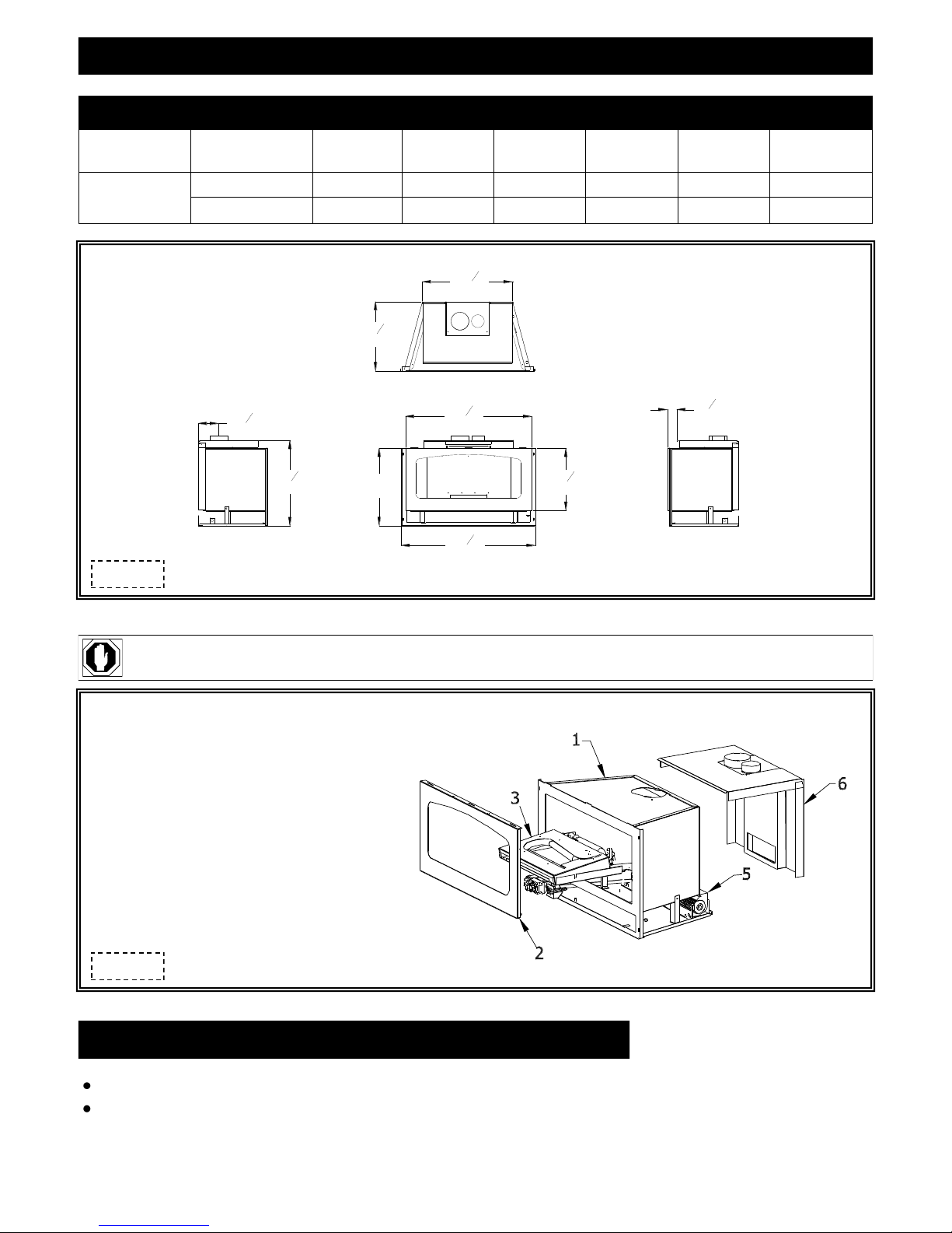
FIREPLACE DIMENSIONS
DESCRIPTION Height Width Back Width Depth Back Height Back to Vent Center
FIREPLACE
DIMENSIONS
Figure 6a
INCHES 18 31-1/4 20-7/8 16-1/8 19-1/2 4-3/4
MILLIMETERS 457 794 530 410 495 121
WARNING: FAILURE TO POSITION PARTS IN ACCORDANCE WITH THESE DIAGRAM S OR FAILURE TO USE ONLY PARTS SPECIFICALLY
APPROVED WITH THIS APPLIANCE MAY RESULT IN PROPERTY DAMAGE OR PERSONAL INJURY.
1. Fireplace insert
2. Spring-loaded latch glass frame assembly
3. Control board with burner cover
4. Log set (see page 24)
5. *150 CFM fan kit
6. Co-linear air duct
*911 and 911-IPI models only
Figure 6b
MINIMUM CLEARANCES TO COMBUSTIBLES
Insert glass to sidewall: 10‖ (254 mm)
Insert top to combustible mantel: 12‖ (305 mm)
PAGE 6
SPECIFICATIONS
#911 / 911-RAD COMPONENTS
911-770 Millivolt Control Board Assembly
700-203 Manual Gas Shut-off Valve
911-135 Burner Assembly
911-G900 Refractory Set
932-500A Log Package
911-002 Glass Frame Assembly
OCK-S50A LP Conversion Kit
815-CL1 Co-Linear Air Chute
911-028* Fan Kit (2)-75 CFM
900-085 4‖ Restrictor Plate
*911 only
#911-IPI COMPONENTS LIST
911-600-IPI IPI Control Board Assembly
700-203 Manual Gas Shut-off Valve
911-135 Burner Assembly
911-G900 Refractory Set
932-500A Log Package
911-002 Glass Frame Assembly
OCK-A50L-I-911-PSE LP Conversion Kit
911-028-IPI Fan Kit (2)-75 CFM
900-085 4‖ Restrictor Plate
700-208
Remote Control
ADDITIONAL COMPONENTS REQUIRED
Vent System; Part #815-CL: For use with minimum 6‖ x 8‖ I.D. masonry or 8‖ I.D. Class A metal chimneys - Includes 12 ft. (3.66 m)
compressed, expandable to 25 ft (7.62 m) co-linear 3‖ x 4‖ flexible chimney, and termination cap.
Part #510: Used in conjunction with #815-CL to extend termination up to a maximum of 30 ft. (9.14 m).
Part #815-CA: For use with minimum 7‖ I.D. Class ‗A‘ metal chimneys - Includes 12 ft. (3.66 m) compressed expandable
to 32 ft. (9.75 m) co-axial 4‖ x 6‖ flexible chimney system, co-axial air duct, and termination cap.
Part #716A: Used in conjunction with #815-CA to extend termination up to a maximum of 40ft. (12.19 m).
Other approved venting: Selkirk, ICC, American Metals, Security
Shrouds - 3 pc & 4 pc.: Standard shrouds are available for this insert and will fit most applications. Custom shrouds may be ordered on a
non-returnable basis. When ordering a custom shroud, please specify existing fireplace front opening height and
width. Grill set or clean face frame (required) in various finishes purchased separately.
or
Blank Shrouds - 3 & 4 pc.: Blank shrouds are available for on-site custom fit applications and are sized to the opening after the insert has
been installed. The interior perimeter is properly sized to fit onto the insert. The outer perimeter must be cut,
formed and finished (painted). Grill set or clean face frame (required) in various finishes purchased separately.
or
Full Door Shrouds: Full door decorative shrouds are available for this insert and are used in place of a standard or blank shroud.
PLACEMENT CLEARANCE REQUIREMENTS
This fireplace must be installed on a level surface capable of supporting the fireplace and venting.
This fireplace insert is to be installed into a solid fuel masonry or factory built non-combustible fireplace that has been installed in
accordance with the National, Provincial, State and local building codes.
Due to high surface temperatures, fireplace should be located out of traffic and away from furniture and draperies.
This fireplace may be installed in a bedroom.
Please be aware of the large amount of heat this fireplace will produce when determining a location.
PAGE 7
EXISTING FIREPLACE SPECIFICATIONS
THIS INSERT IS APPROVED FOR INSTALLATION IN MASONRY AND FACTORY-BUILT SOLID FUEL BURNING FIREPLACES.
EXISTING FIREPLACE REQUIREMENTS
The existing fireplace & chimney must be clean and in good working order and constructed of non-combustible materials.
A gas line must be able to be installed to insert.
Provisions made to provide electrical power to operate insert fan and thermostatic control (if used).
Any chimney clean-outs must fit properly.
Existing Chimney must be comprised of one of the following: Factory built chimney: Co-linear - 8‖ (203 mm) minimum inside diameter.
Co-axial - 7‖ (178 mm) minimum inside diameter.
Masonry Chimney: 6" x 8" minimum inside diameter.
Existing Chimney Height: Minimum: 12 ft. (3.66 m)
Maximum: Co-axial venting: 40 ft. (12.19 m)
Co-linear venting: 30 ft. (9.14 m)
NOTE: It is helpful to have two people complete next step in determining
chimney height.
Determine length of your existing chimney:
1. Remove and discard existing chimney cap.
2. Measure from fireplace base to top of chimney.
Subtract 24‖ (610 mm).
This is total length of co-linear flexible aluminum required.
MEASUREMENT FROM FIREPLACE BASE TO TOP OF CHIMNEY:____________
LESS 24" (610 mm) (HEIGHT OF INSERT): -24" (610 mm)
TOTAL CHIMNEY LENGTH REQUIRED: ____________
CAUTION: This appliance must not be connected to or joined with any other
chimney flue serving another appliance.
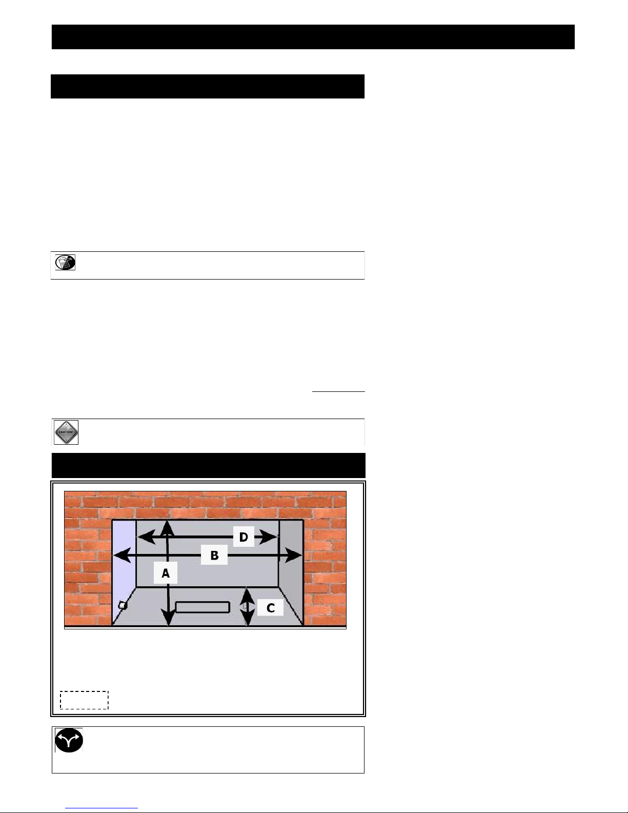
EXISTING FIREPLACE MINIMUM OPENING REQUIREMENTS
(A) Height: ……………………………………..19" (483 mm)
(B) Front Width:……………………………….31-1/2" (800 mm)
(C) Depth:………………………………………16-1/4" (413 mm)
(D) Back Width:………………………………..21" (606 mm)
Figure 8a
All dimensions are minimum requirements
PAGE 8
PREPARE EXISTING FIREPLACE
Any removed parts must be capable of reinstallation if this insert is ever removed (removal of rivets or screws is acceptable).
The refractory, glass doors, screen rails, screen mesh and log grates may be removed from existing fireplace before installing this gas
fireplace insert. Any smoke shelves, shields and baffles may be removed if attached by mechanical fasteners. If necessary, remove firebrick
to obtain at least minimum opening requirements.
The fireplace flue damper can be fully blocked open or removed for installation of this gas fireplace insert. Remove existing chimney cap.
Clean chimney and inside of fireplace to prevent creosote smell from entering the home.
Place ‗THIS UNIT HAS BEEN MODIFIED‘ label at bottom of existing firebox so it will be visible if this gas fireplace insert is removed.
Cutting of any sheet metal parts is prohibited, except the metal floor. If metal floor is removed, the insert must be placed directly on metal
base of metal fireplace.
Run any necessary electrical wiring to insert.
GLASS FRAME ASSEMBLY
WARNING: DO NOT OPERATE THIS FIREPLACE WITH GLASS REMOVED, CRACKED OR BROKEN. REPLACEMENT
OF GLASS ASSEMBLY, #700-08T SHOULD BE DONE BY A LICENSED OR QUALIFIED SERVICE PERSON.
WARNING: DO NOT REMOVE GLASS ASSEMBLY WHEN HOT!
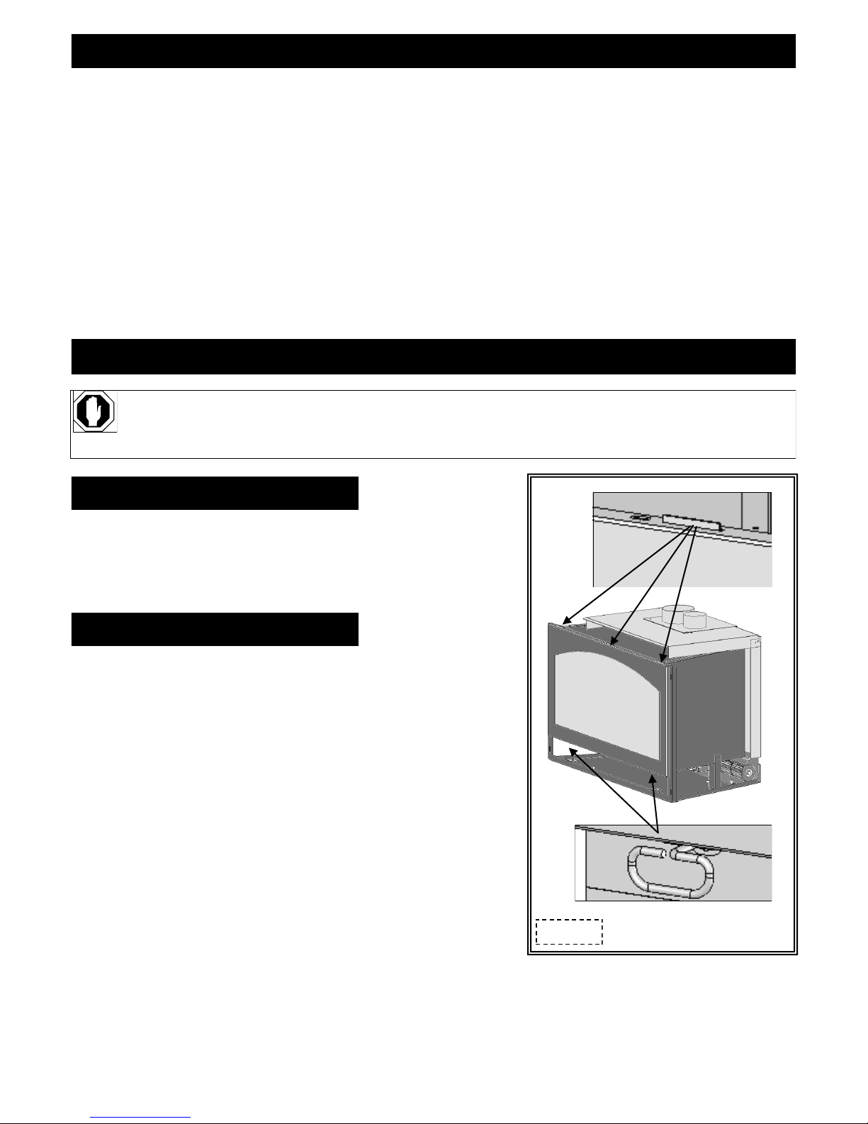
REMOVE GLASS FRAME ASSEMBLY
1. Locate spring-loaded handles securing glass frame assembly at bottom of firebox.
2. Pull bottom handles out and ‗down‘ to release glass frame assembly bottom.
3. Pull bottom of glass frame assembly out and lift up off tabs at top of firebox.
INSTALL GLASS FRAME ASSEMBLY
A. Place glass frame assembly top over tabs at top of firebox.
B. Pull bottom handles out and ‗up‘ to secure glass frame assembly bottom.
Figure 9a
PAGE 9
FAN DIRECT WIRE INSTALLATION
DIRECT WIRE CONNECTION MUST BE PERFORMED BY A QUALIFIED ELECTRICIAN.
911-RAD: Optional: #911-028 fan kit
#600-083C speed control, receptacle assembly
911: This fireplace insert comes complete with a fan and thermostatic control switch already installed. A speed control, receptacle,
and power cord have been installed, wired and mounted in a removable electrical box panel on right side of fireplace.
911-IPI: This fireplace insert comes complete with a fan kit already installed. A double receptacle and power cord have been installed,
wired and mounted in a removable electrical box panel on right side of fireplace.
NOTE: If wiring to pre-installed electrical box is desired, wiring should be run prior to permanently setting insert in place and
connecting vent system.
If this fireplace insert is being installed in minimum opening dimensions, wiring may need to be completed after fireplace insert
DIRECT WIRE INSTALLATION: The cord must be removed and wiring disassembled. Insert 110V-120V wiring (with ground) through
romex connector and wire to box cover assembly, matching black, white & green (ground) wires to
corresponding wires on electrical box cover assembly.
is set in place.
WARNING: This appliance is equipped with a three-prong (grounding) plug for protection against shock hazard and should be plugged
directly into a properly grounded three-prong receptacle. Do not cut or remove grounding prong from this plug. Do not allow
any excess fan cord to touch fireplace.
NOTE: Code approved line voltage wiring 14 gauge or better must be used when wiring this assembly. Refer to local electrical codes for
specific requirements in your area.
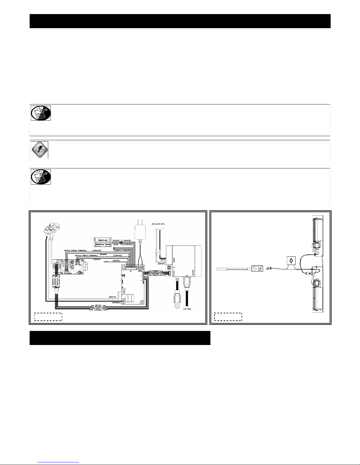
911-IPI WIRING SCHEMATIC
Figure 10a Figure 10b
911 WIRING SCHEMATIC
DIRECT WIRE INSTALLATION
1. 911: Loosen (but do not remove) screw securing removable access panel (with electrical box & romex connector installed) from
right side of fireplace. Remove access panel.
2. 911 / 911-RAD / 911-IPI: Remove box cover assembly to expose wiring.
3. Remove existing cord and insert 110V-120V wiring (with ground) through romex connector, wiring to box cover assembly, matching
black (hot), white (neutral), and green (ground) wires to corresponding wires on box cover assembly using (3) wire nuts obtained when
removing existing cord.
4. Reattach box cover assembly with (2) screws provided.
Refer to page 19 for instructions on completing fan wiring after insert has been installed.
This appliance, when installed, must be electrically grounded in accordance with local codes, or in the absence of local codes,
with the National Electrical Code, ANSI/NFPA 70, or the Canadian Electrical Codes, CSA C22.1
PAGE 10
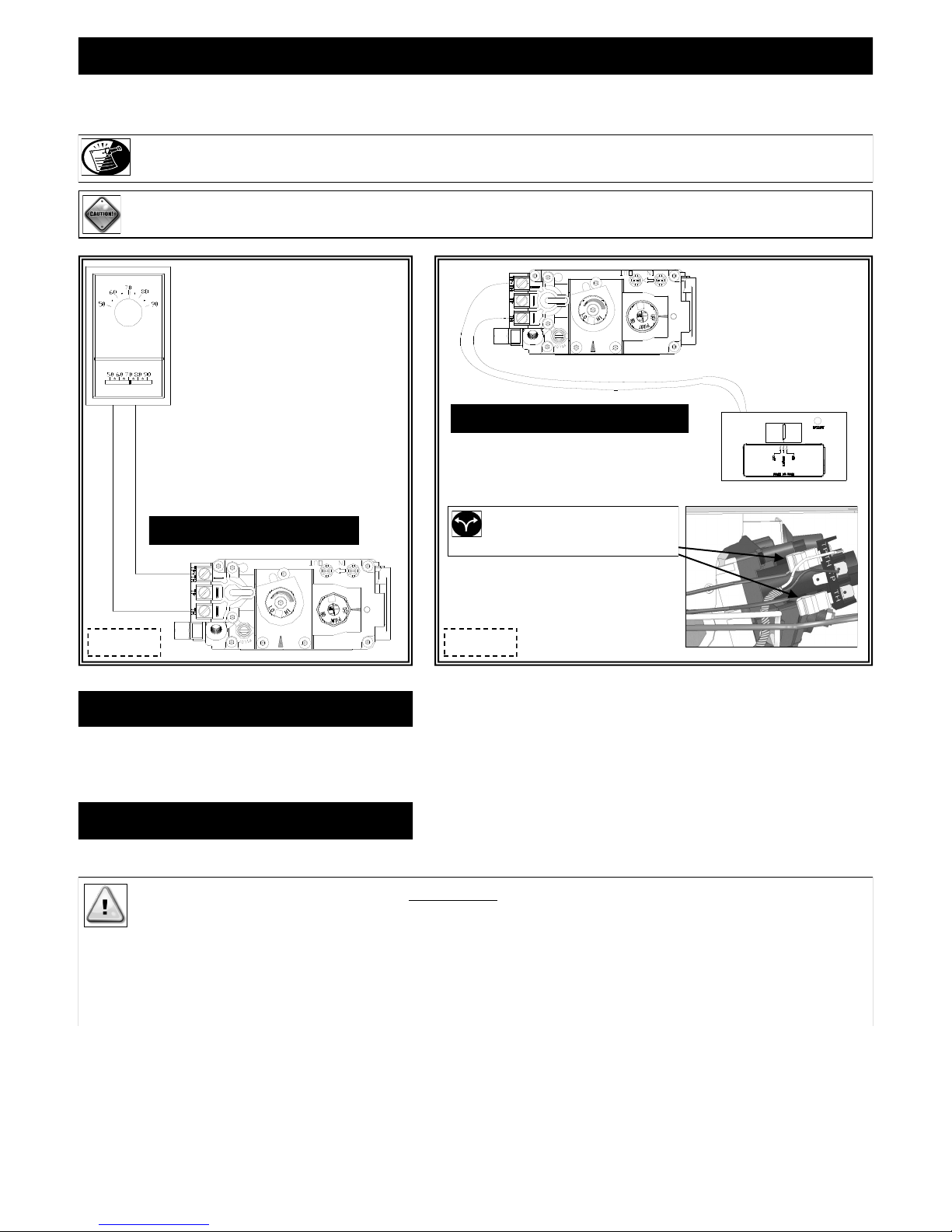
THERMOSTAT / WALL SWITCH / REMOTE (911 & 911-RAD only)
If desired, a thermostat (wireless style also available), wall switch, or remote control assembly may be used to turn fireplace OFF and ON.
Only ONE of these may be installed. Follow instructions included with chosen assembly.
NOTE: INSTALLATION OF THERMOSTAT OR WALL SWITCH SHOULD BE PERFORMED BY A QUALIFIED INSTALLER .
CAUTION: DO NOT CONNECT HIGH VOLTAGE (115V) WIRE TO GAS VALVE!
Remote Control Wiring Diagram
OPTIONAL: Disconnect ON/OFF
Thermostat Wiring Diagram
rocker switch wires
from back of gas valve.
Figure 11b Figure 11a
WALL SWITCH / THERMOSTAT:
Run low-voltage (thermostat) wires from terminals on gas valve to desired location of wall switch or thermostat.
Attach appropriate connectors to wall switch / thermostat wires and connect to top and bottom terminals marked TH/TPTH on gas valve.
REMOTE CONTROL:
Follow instructions included with remote control.
IMPORTANT: If ON/OFF rocker switch wires are not disconnected, the ON/OFF rocker switch on control board must be in OFF
position for proper operation of any of these components.
thermostat, or remote control will not turn fireplace OFF when it has been turned ON by the rocker switch.
Fireplace must be turned ON and OFF by same method.
Example: If fireplace is turned ON by remote control, it must be turned OFF by remote control.
IMPORTANT: The insulated cover included with remote control must be placed over remote receiver to prevent overheating.
IMPORTANT: If rocker switch is ON, fireplace burner will operate until it is turned OFF by rocker switch. A wall switch,
PAGE 11
GAS LINE CONNECTION
#911-RAD owners: If installing optional fan kit #911-028, please do so now before connecting gas line.
GAS CONVERSION
This fireplace is manufactured for use with Natural Gas. An LP conversion kit is included with this fireplace.
Follow instructions included with conversion kit if converting to LP gas.
ATTENTION: The conversion shall be carried out in accordance with the requirements of the provincial authorities having jurisdiction and
in accordance with the requirements of the ANSI Z223.1 installation code.
CAUTION: Installation of the gas line must only be done by a qualified person in accordance with local building codes, if any.
If not, follow ANSI 223.1.
Commonwealth of Massachusetts: Installation must be done by a licensed plumber or gas fitter.
NOTE: A listed (and Commonwealth of Massachusetts approved) 12” (13 mm) T- handle manual shut-off valve and flexible gas
connector (included) are connected to the 1/2” (13 mm) control valve inlet. If substituting for these components, please
consult local codes for compliance.
NOTE: This fireplace is equipped with a 3/8”(10 mm) x 18” (457 mm) long flexible gas connector and manual shut-off valve. The gas
pressure testing of the gas line at test pressures equal to or less than ½ psi (3.5 kPa).
line should be run to the point of connection where the shut-off valve and flexible gas line will connect.
NOTE: The appliance and its individual shutoff valve must be disconnected from gas supply piping system during any pressure
testing of that system at pressures in excess of ½ psi.
NOTE: The appliance must be isolated from the gas supply piping system by closing its individual manual shut-off valve during any
NOTE: For high altitude installations, consult local gas distributor or authority having jurisdiction for proper rating methods.
IMPORTANT: The efficiency rating of this appliance is a product of thermal efficiency rating determined under continuous operating
conditions and was determined independently of any installed system.
NOTE: If installing this insert into minimum opening dimensions, the gas line may need to be run after placement due to space
limitations.
If installing this gas fireplace insert into a factory-built fireplace and the factory-built fireplace has no access hole provided, an access
hole of 1 ½"(38 mm) or less may be drilled through the lower sides or bottom of the firebox in a proper workmanship like manner. This
access hole must be plugged with non-combustible insulation after the gas supply line has been installed.
IMPORTANT: Do not run gas line in a manner that would obstruct fan operation.
911 / 911-RAD 911-IPI
NATURAL GAS LP GAS NATURAL GAS LP GAS
MINIMUM INLET GAS PRESSURE
MAXIMUM INLET GAS PRESSURE 10.5 inches W.C. 13.0 inches W.C. 10.5 inches W.C. 13.0 inches W.C.
MANIFOLD PRESSURE (HI) 3.5 inches W.C 10.0 inches W.C. NA NA
MANIFOLD PRESSURE (LO) 1.7 inches W.C. 6.3 inches W.C NA NA
ORIFICE SIZE #32 #50 #32 #50
5.0 inches W.C.
(7.0 W.C. recommended)
11.0 inches W.C.
(recommended)
5.0 inches W.C.
(7.0 W.C. recommended)
11.0 inches W.C.
(recommended)
INPUT BTU/hr. 36,500 30,000 36,500 30,000
MINIMUM INPUT BTU/hr. 27,500 23,500 27,500 23,500
PAGE 12
INSTALLATION
IMPORTANT: All steps as outlined in „PREPARE EXISTING FIREPLACE‟ must be completed before continuing with this installation.
APPROVED VENTING
Kozy Heat #815-CL Co-Linear Vent System. Follow instructions on pages 14-16.
Kozy Heat #815-CA Co-Axial Vent System. Follow instructions on pages 17-18.
Selkirk, ICC, American Metals, Security. Follow instructions included from vent pipe
manufacturer as well as venting requirements as outlined in this installation manual.
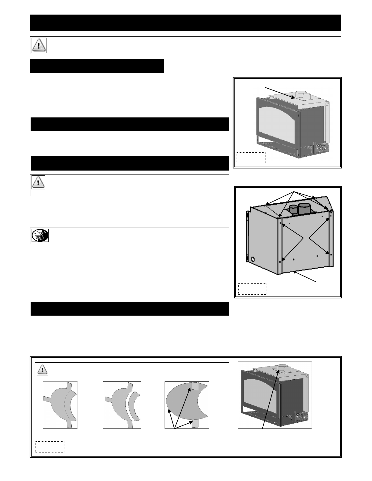
AIR DUCT REMOVAL
Remove air duct by lifting up and off top of insert. Follow instructions below and on
following pages for vent system attachment to air duct.
#911XL-MSP MASONRY SIDE PANEL INSTALLATION (OPTIONAL)
IMPORTANT: For use when insert is installed in an existing masonry opening.
This kit must be attached to air duct (manifold) prior to vent system
connection.
Air Duct
Figure 13a
This kit includes: (1) Right side panel
(1) Left side panel
(12) Sheet metal screws
NOTE: If air duct and masonry side panels are not placed „outside‟ flanges at
insert bottom, a rattling noise may occur when fan is in operation.
1. If air duct on insert is not positioned outside flange at bottom, remove and
reposition.
2. Position each side panel outside the flanges on insert bottom, aligning (2) holes in
top and (2) holes in back of masonry side panels with corresponding holes in air
duct. Secure with screws included.
Figure 13a
Masonry side panels and air duct must be
positioned outside flange at bottom of insert
This installation will be continued at a later point.
RESTRICTOR INSTALLATION
Each installation is unique and affected by various factors including venting configuration, altitude and climate. Therefore, after fireplace
insert installation is complete, a restrictor may be required or may need to be removed or modified.
Page 41 has information on restrictor recommendations depending on burner flame appearance and instructions on installation after venting
is completed.
IMPORTANT: Do not install if venting configuration is at minimum requirements.
Large Restrictor
Figure 13b
Remove tab (s) to create
small restrictor
Bend tabs to approx. 80 degree
angles to create tension to hold
itself in place when installed.
PAGE 13
Slide restrictor into exhaust pipe with tabs
pointing toward you.
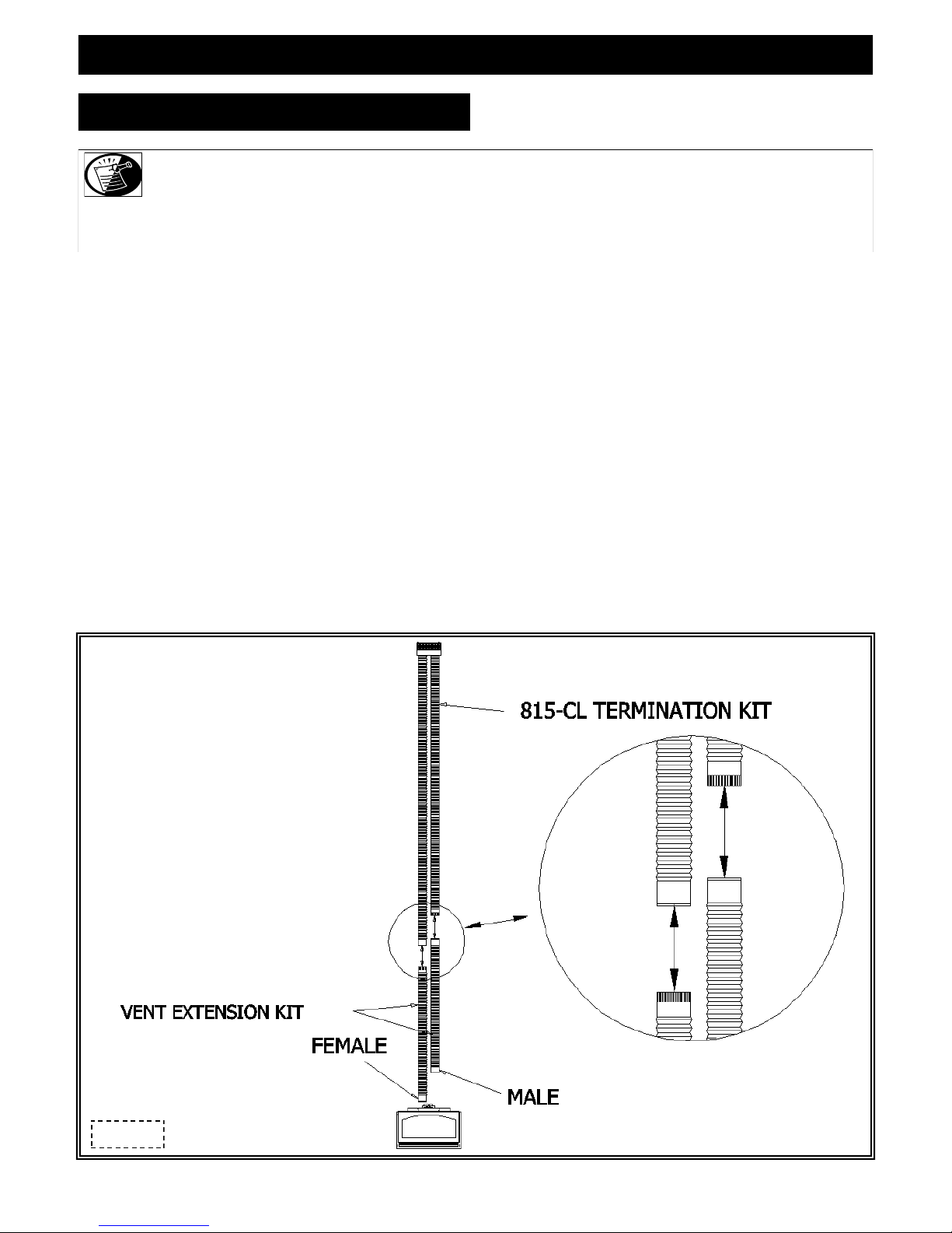
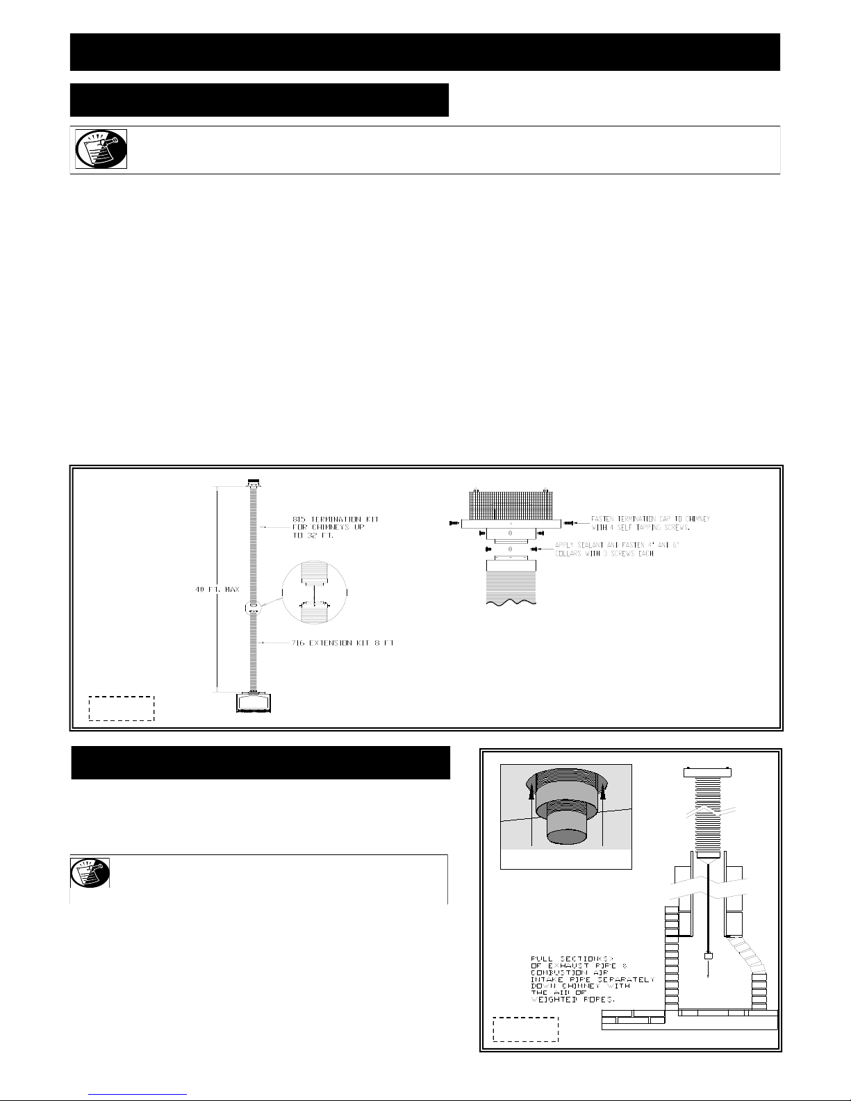
VENTING INSTALLATION
KOZY HEAT #815-CL CO-LINEAR VENT SYSTEM
NOTE: The co-linear pipe included with this vent system is designed to extend up to 25 ft. (7.62 m). If additional length is required, Part
#510 is available to extend venting to a maximum of 30 ft . (9.14 m).
NOTE: If using „stub‟ method for combustion air pipe, extending it is not necessary. Determine length needed from insert air duct
(4 ft. (1.22 m) minimum) to above damper opening in existing chimney. Remove excess combustion air pipe from end without
A. Carefully extend 3‖ combustion intake and 4‖ exhaust pipes (and extension kit if used) to equal total chimney length required.
B. If using „Full Connection‟ method:
1. Slide 3" intake pipe (end without collar) over collar on termination cap. Secure with 3 self-tapping screws (provided).
2. Place bead of sealant around inner edge of 4" exhaust pipe (end without collar) and slide onto corresponding collar on termination
cap. Secure with 3 self-tapping screws (provided). Apply additional sealant around joint to ensure a seal.
C. If an extension kit is being used, it must be connected as follows:
Exhaust extension: Apply a liberal bead of sealant around exhaust adaptor (male) extension pipe and slide into female connector on end of
4‖ exhaust pipe already attached to the chimney termination plates. Secure with 3 self-tapping screws, (provided). To
ensure an air-tight seal, additional sealant should be applied at the point of connection.
Combustion intake extension: Apply a liberal bead of sealant (provided) around male end of extension kit and slide into female end
of 3‖ combustion intake pipe attached to chimney termination plates. Secure with 3 self-tapping screws
(provided). To ensure an air-tight seal, additional sealant should be applied at point of connection.
collar. Continue with Step B. #2 below.
Figure 14a
PAGE 14
VENTING INSTALLATION KOZY HEAT #815-CL CO-LINEAR VENT SYSTEM (cont.)
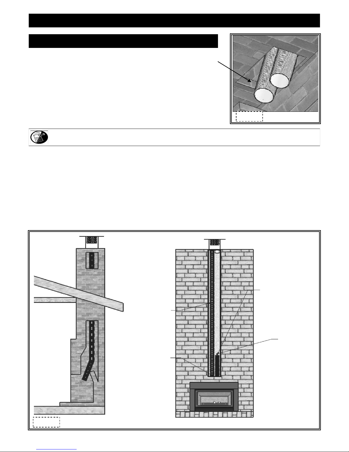
RUN VENTING THROUGH EXISTING CHIMNEY
We strongly suggest wrapping first 3 ft.(914 mm) of vent system below termination cap
with non-faced fiberglass insulation (secure with wire) before running it through existing
chimney. This will prevent cold air from coming down existing chimney.
Figure 15a
NOTE: If offsets are present in existing chimney, it may be easier to place a weighted rope around the end of each pipe to guide them
through it. DO NOT ATTEMPT TO TIE ONE ROPE AROUND BOTH PIPES.
1. Guide rope, if used, and flexible pipe(s) down existing chimney. See illustration at lower left.
2. To secure chimney termination cap to existing chimney, apply a liberal bead of sealant (provided) around top of existing chimney. Set
termination cap into position as instructed in installation manual included with chosen vent system.
3. From inside existing fireplace opening, CAREFULLY pull ropes down until 4" exhaust pipe and 3‖ combustion air intake (if using
‗full connection method‘), are into existing fireplace.
STUB VENTING: From inside existing fireplace, insert a minimum 4ft. (1.22m) section of combustion air pipe (end without collar) past
damper opening and into existing fireplace. See illustration at lower right.
We strongly suggested placing non-faced fiberglass insulation between vent pipes and existing chimney to prevent heat loss up chimney,
being careful not to block end pipe if using stub method.
Figure 15b
4" exhaust flex pipe
must be connected
to collar on
fireplace insert and
termination cap
Seal area around
vent pipes with
non-faced fiberglass
insulation
PAGE 15
Minimum 4 ft. (1.22m) section
of 3" combustion air flex pipe
DO NOT block pipe
end with insulation or
any other sealing
materials
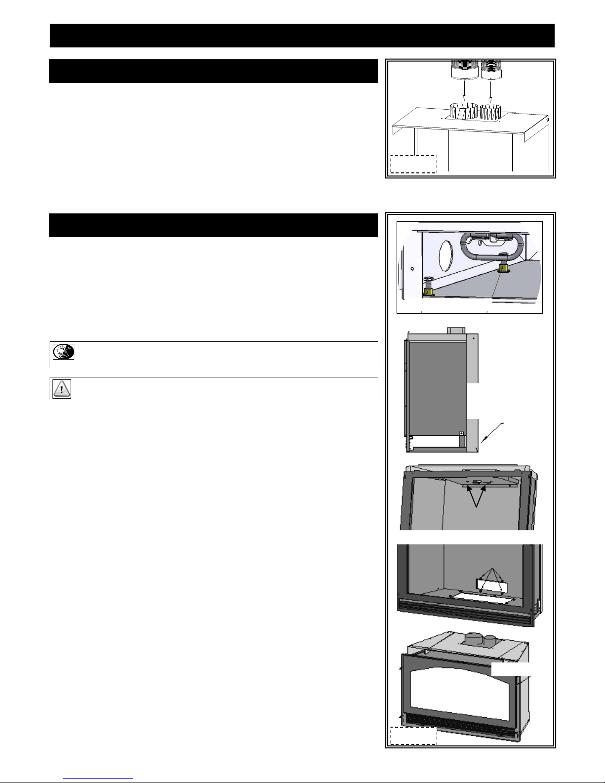
VENTING INSTALLATION
CONNECT #815-CL VENT SYSTEM TO AIR DUCT
1. Place air duct (previously removed from insert top, page 13) into existing fireplace
opening.
2. Place a bead of sealant (provided) around 4‖ exhaust pipe. Slide exhaust pipe inside
4" collar air duct. Secure with (3) ½" self-tapping screws, provided. Apply additional
sealant around joint to ensure an air-tight seal.
3. Apply a liberal bead of sealant (provided) around 3‖ collar on the air duct. Slide 3‖
combustion intake pipe over the collar. Secure with (3) ½" self-tapping screws,
provided. To ensure an air-tight seal, apply additional sealant around joint.
ATTACH AIR DUCT TO INSERT
1. Slide insert into fireplace opening.
2. If necessary, level insert by threading leveling bolts (included in components packet)
into nuts mounted inside lower air passage.
Figure 16a
3. Attach air duct to insert by aligning two holes in insert top to studs on each side of 4"
exhaust duct, and four holes at back of insert to mounting studs at lower end of air
duct.
NOTE: To prevent rattling noises that may occur during fan operation, position air
duct back and sides on the OUTSIDE of insert bottom flanges.
IMPORTANT: Before completing steps 4 & 5, ensure air duct gasket is properly seated.
4. Locate baffle with seasonal heat dump inside firebox, noting (2)access holes on each
side of heat dump. Secure air duct to insert through access holes with (2) 1/4" nuts.
5. Using a 7/16‖ wrench, secure lower end of air duct to insert firebox with (4) 1/4"
nuts.
If installing optional #911-MSP:
Align (4) holes in insert face to corresponding holes in masonry side panels. Secure with
remaining screws included with kit.
Leveling legs (2 per side)
Position air duct back
and sides outside insert
bottom flanges
(2) each side
Figure 16b
PAGE 16
VENTING INSTALLATION
KOZY HEAT #815-CA CO-AXIAL VENT SYSTEM
NOTE: The co-axial pipe included with this vent system is designed for chimneys up to 32 ft ( 9.75 m). If additional length is required,
Part #716-A is available to extend the venting to a maximum of 40 ft (12.19 m).
The 4" exhaust flex pipe and 6" combustion air flex pipe are coiled and packaged separately.
Carefully extend 4‖ and 6‖ flex pipes and extension kit (if used) to equal total chimney length required.
If an extension kit is used, it must be connected to 4" exhaust and 6" combustion air intake pipe included with #815-CA Vent Kit.
EXHAUST CONNECTION:
Apply liberal bead of sealant (provided) around 4‖ exhaust adaptor (with external notches) on extension kit and slide into female connector
on end of 4‖ exhaust pipe. Secure with 3 self-tapping screws, (provided). To ensure an air-tight seal, apply additional sealant at point of
connection.
COMBUSTION INTAKE CONNECTION:
Slide extended 6" combustion intake pipe included with 815-CA kit over extended 4" exhaust pipe included with 815-CA kit. Apply
liberal bead of sealant (provided) around 6‖ combustion intake adaptor (with external notches) on extension kit and slide it over extended
4" exhaust pipe extension and into female end of 6‖ combustion intake pipe. Secure with 3 self-tapping screws (provided). To ensure an
air-tight seal, apply additional sealant at point of connection. The 4" exhaust pipe is now inside 6" intake pipe.
A. Apply liberal bead of sealant (provided) around inside edge of 4‖ exhaust pipe, (end without collar) and slide it onto 4" collar on
vent cap. Secure with 3 equally spaced self-tapping screws through both sections. Apply additional sealant around joint to ensure
an air-tight seal.
B. Apply liberal bead of sealant (provided) around inside edge of 6‖ combustion intake pipe, (end without collar) and slide it onto 6‖
collar on vent cap. Secure with 3 equally spaced self-tapping screws through both sections. Apply additional sealant around joint
to ensure an air-tight seal. The 4" exhaust pipe will be inside the 6" combustion intake pipe.
Figure 17a
RUN VENTING THROUGH EXISTING CHIMNEY
We strongly suggest wrapping first 3 ft.(914 mm) of vent system below
termination cap with non-faced fiberglass insulation (secure with wire)
before running it through existing chimney. This will prevent cold air
from coming down existing chimney.
NOTE: If offsets are present in existing chimney, it may be easier to
place a weighted rope around end of each pipe to guide them
through it. DO NOT ATTEMPT TO TIE ONE ROPE
A. Guide ropes, if used, and flexible pipes down existing chimney.
B. To secure chimney termination cap to existing chimney, apply
liberal bead of sealant around top of existing chimney, set
termination cap into position. Secure with (4) 1-1/2‖ self-drilling
screws (provided).
Figure 17b
PAGE 17

VENTING INSTALLATION
CONNECT #815-CA CO-AXIAL VENT SYSTEM TO AIR DUCT
A. Place air duct into existing fireplace opening.
B. Place bead of sealant (provided) around 4‖ flex pipe and slide into 4‖ collar on
air duct. Secure with (2) self-tapping screws (provided).
Apply additional sealant around joint to ensure an air-tight seal.
C. Apply bead of sealant around 6‖ collar on flex pipe and slide into 6‖ collar on
air duct. Secure with (1) self-tapping screw (provided) through center front of
this connection. Apply additional sealant around joint to ensure an air-tight seal.
ATTACH AIR DUCT TO INSERT
1. Slide insert into fireplace opening.
2. If necessary, level insert by threading leveling bolts (included in components
packet) into nuts mounted inside lower air passage.
3. Attach air duct to insert by aligning two holes in insert top to studs on each side
of 4" exhaust duct, and four holes at back of insert to mounting studs at lower
end of air duct.
Figure 18a
Leveling legs (2 per side)
NOTE: To prevent rattling noises that may occur during fan operation, position
air duct back and side flanges on OUTSIDE of insert bottom flanges.
IMPORTANT: Before completing steps 4 & 5, ensure air duct gasket is
properly seated.
4. Locate baffle with seasonal heat dump inside firebox, noting (2) access holes
(A) on each side of heat dump. Secure air duct to insert through access holes
with (2) 1/4" nuts.
5. Using a 7/16‖ wrench, secure lower end of air duct to insert firebox with (4)
1/4" nuts.
If installing optional #911-MSP:
Align (4) holes in insert face to corresponding holes in masonry side panels.
Secure with remaining screws included with kit.
Position air duct back
and sides outside insert
bottom flanges
(2) each side
Figure 18b
PAGE 18

COMPLETE FAN WIRING INSTALLATION
#911-RAD with optional fan kit #911-028
1. If not previously done, turn gas valve and manual shut off valve to OFF. Disconnect gas line from manual shut off valve.
2. Remove glass frame assembly. Refer to page 9.
3. Slide left, then right fan through lower grill opening (right side of gas valve), positioning onto corresponding mounting studs on
fireplace floor. Secure with nuts, included.
4. Connect flexible gas line to manual shut off valve. Turn manual shut off valve to ON.
CAUTION: CHECK CONNECTION FOR LEAKS.
#911 & #911-RAD (#600-083C Speed Control / Receptacle assy. w/ power cord available for #911-RAD models).
1. Secure electrical access panel to side of fireplace.
2. Place thermostatic control switch on bottom of firebox.
3. Plug power cord into electrical box receptacle.
4. Turn speed control counter-clockwise until it ‗clicks‘. This is the OFF position.
5. Turn speed control ON by turning knob clockwise past the ‗click‘ - this is the highest setting.
NOTE: This appliance must be electrically grounded and connected in accordance with local codes, or in the absence of local codes, with
the National Electrical Code, ANSI/NFPA 70 Current Edition, or the Canadian Electrical Code CSA C22.1.
NOTE: This fan will not operate until speed control turns ON and sufficient heat has been applied to temperature control switch.
The fan will turn ON and OFF automatically as fireplace heats and cools. Adjust fan to desired speed while it is running.
TEMPERATURE CONTROL SWITCH POSITION
Before adjusting temperature control switch, unplug 3-prong plug
on fan cord from receptacle. Adjust position of temperature control
switch to a warmer location under firebox to turn fan ON sooner or
move it to a cooler location under firebox to turn fan ON later. The
fan will turn on when sensor in temperature control switch reaches
110° F and will turn OFF when sensor reaches 90° F.
After adjustment, plug 3-prong plug on fan cord into receptacle.
Temperature Control Switch (looking through lower grill opening).
Figure 19a
#911-IPI
1. Secure electrical access panel to side of fireplace.
2. Plug power cord into electrical box receptacle.
3. Upon complete installation of this fireplace, follow operating instructions as outlined in this manual.
NOTE: This appliance must be electrically grounded and connected in accordance with local codes, or in the absence of local codes, with
the National Electrical Code, ANSI/NFPA 70 Current Edition, or the Canadian Electrical Code CSA C22.1.
PAGE 19

CONTROL BOARD REMOVAL / INSTALLATION
CONTROL BOARD REMOVAL
CAUTION: If burner and/or pilot have been burning, use appropriate protection to
avoid burns or personal property damage before removing any components.
1. 911/ 911-RAD: Turn gas control knob to OFF.
911-IPI: Use remote to turn fireplace off.
2. Shut off gas supply at manual shut-off valve.
3. Disconnect gas line flex tube from manual shut-off valve.
4. 911/ 911-RAD: Disconnect any wall switch, remote control, or thermostat wires
from TH / THTP terminals on gas valve.
911-IPI: Unplug all components from electrical outlet, disconnect all wiring
harnesses attached to gas valve.
5. Remove glass assembly. Page 9.
6. Remove logs.
7. Remove burner assembly from firebox.
8. Remove burner heat shield.
9. Remove (8) nuts securing control board. Lift board up and out of firebox.
CONTROL BOARD INSTALLATION
WARNING: DO NOT OPERATE THIS FIREPLACE WITHOUT SEALING GASKET
(LOCATED UNDER CONTROL BOARD) IN PLACE.
1. Place control board in firebox, aligning holes in control board with mounting studs in
firebox bottom. Ensure sealing gasket in in place on firebox bottom!
CAUTION: Before securing, check that all wires are clear and unobstructed. Do not
allow any wires or gas flex line to come in contact with fan terminals.
Secure control board to firebox bottom with (8) 1/4‖ nuts.
2. Install burner assembly; burner tube is positioned over burner orifice and sides are
inside control board flanges. Place burner heat shield over control board (flanges
facing down).
3. Install pilot shield around pilot assembly.
4. Connect gas line to manual shut-off valve.
5. 911/ 911-RAD: Connect any wall switch, remote control or thermostat wires to
terminals on valve marked TH / THTP.
911-IPI: Reconnect all wiring harnesses to gas valve. Plug components into
electrical outlet.
6. Install log set. Page 24.
7. Install glass frame assembly. Page 9.
8. Verify proper log placement, operation of insert and any electrical components.
CAUTION: CHECK ALL CONNECTIONS FOR LEAKS, WHETHER FIELD OR FACTORY
M ADE.
Figure 20a
PAGE 20

ZC SHROUD ASSEMBLY AND INSTALLATION
Shroud assembly includes: (1) Shroud top (8) Phillips head screws
(1) Shroud left side (2) Shroud extensions
(1) Shroud right side with on/off rocker switch mounting hole
You will need a grill set or a clean face frame (sold separately).
911 / 911-RAD : You will need the following items from insert components packet: Rocker Switch Wires and On/Off Rocker Switch.
Grill option: Remove nuts from upper grill. Place grill rods through holes in shroud top section. Secure with nuts. If necessary, recess
upper grill by re-positioning in one of three mounting holes.
Clean Face frame option: Follow instructions included with clean face frame.
1. Secure right and left shroud sections to top section by aligning (2) holes in side sections to holes in top section. Secure with phillips
head screws (2 ea. side).
OPTIONAL: Attach shroud extensions by aligning slots in shroud with desired hole in shroud extension. Secure with phillips head screws.
Figure 21a
911 / 911-RAD: Snap rocker switch into place on shroud. Slide one connector on each rocker switch wire to the rocker switch.
2. Attach shroud to insert by placing tabs on left and right shroud pieces into slots in insert. The shroud will set into place.
911 / 911-RAD: Slide remaining connectors on rocker switch wires to terminals on gas valve marked TH / THTP.
Grill option: Remove nuts from lower grill, insert grill bolts through lower hinges on insert. Attach and tighten nuts.
Figure 21b
PAGE 21

MASONRY SHROUD ASSEMBLY & INSTALLATION
Shroud assembly includes: (1) Shroud top (8) Phillips head screws
(1) Shroud left side (1) Set ‗inside fit‘ brackets
(1) Shroud right side with on/off rocker switch mounting hole
You will also need upper grill from grill set or a clean face frame (sold separately).
911 / 911-RAD: You will need the following items from insert components packet: Rocker switch wires and On/Off Rocker Switch
Grill option: Remove nuts from upper grill. Place grill rods through holes in shroud top section. Secure with nuts.
Clean Face frame option: Follow instructions included with clean face frame.
1. Secure right and left shroud sections to top section by aligning (2) holes in side sections to holes in top section. Secure with phillips
head screws (2 ea. side).
911 / 911-RAD: Snap rocker switch into place on shroud. Slide one connector on each rocker switch wire to the rocker switch.
2. Attach shroud to insert by inserting tabs (A) on left and right shroud sections to holes (B) in insert face. The shroud will set down into
place.
Screws are secured from bottom.
Figure 22a
Snap On/Off rocker switch into
mounting hole as shown.
OUTSIDE FIT APPLICATIONS:
911 / 911-RAD: Slide remaining connectors on rocker switch wires to terminals on gas valve marked TH / THTP.
Grill option: Remove nuts from lower grill, insert grill bolts through lower hinges on insert. Attach and tighten nuts.
Figure 22b
INSIDE FIT APPLICATIONS: (You will require ‗inside fit‘ brackets included with shroud assembly).
1. Remove glass frame assembly. Refer to page 9 if necessary.
2. Referring to illustration at right, use tin snips to remove lower end of (4) mounting tabs on shroud
side sections.
Figure 22c
PAGE 22

MASONRY SHROUD ASSEMBLY & INSTALLATION cont.
IMPORTANT- MOUNTING BRACKET ORIENTATION
Right mounting bracket is notched out at the bottom. Figure 23a.
Flanges on both mounting brackets face the inside of insert. Figure 23a.
1. Align holes in mounting brackets to corresponding holes in insert face, making sure
brackets are positioned as shown in Figure 23a.
Secure with screws provided (Figure 23b).
2. Position tabs (lower end previously removed) on shroud into slots in insert face,
aligning oblong holes on inside flange of shroud side sections to holes in mounting
brackets. Secure with (4) screws (C), 2 each side. Figure 23c.
911 / 911-RAD: Slide remaining connectors on rocker switch wires to terminals on gas
valve marked TH / THTP.
Grill option: Remove nuts from lower grill, insert grill bolts through lower hinges on
insert.
OPTIONAL MASONRY PANEL INSTALLATIONS:
1. Remove screws (A) (2 ea. side) securing masonry panels. Figure 23b.
2. Align holes in mounting brackets to corresponding holes in insert face & masonry
panels, making sure brackets are positioned as shown in Figure 23b. Secure with
screws removed in step1and included in shroud components packet.
3. Position tabs (lower end previously removed) on shroud into slots in insert face,
aligning oblong holes on inside flange of shroud side sections to holes in mounting
brackets. Secure with (4) screws (C), 2 each side. Figure 23c.
911 / 911-RAD: Slide remaining connectors on rocker switch wires to terminals on gas
valve marked TH / THTP.
Grill option: Remove nuts from lower grill, insert grill bolts through lower hinges on
insert. Attach and tighten nuts. Figure 23d.
Figure 23a
A
Figure 23b
B
Figure 23d
C
Figure 23c
PAGE 23

#932-500A LOG SET INSTALLATION
ATTENTION: If converting to LP (propane) gas, do so now before installing log set. Follow instructions included with conversion kit.
NOTE: Log numbers are marked on bottom of each log. Refer to following instructions and illustrations for proper placement.
CAUTION: Do not place logs directly over burner port holes. Improper log placement may affect flame appearance and cause excessive
soot to build up on logs and glass.
AD
Figure 24a
BI
HB
AG
AJ
Align notches on bottom of BI log with brackets in burner cover. Set down into position.
Position AD, AG, HB & AJ logs onto burner cover, pressing down onto pins.
C
M
M
Figure 24b
Use a steel or stiff bristle nylon brush to distribute Rock Wool Embers onto logs and burner.
Align hole in bottom of right M log to knob on HB log.
Position remaining M log and C log as shown above.
PAGE 24

911 / 911-RAD VALVE & PILOT ASSEMBLY COMPONENTS
THERMOCOUPLE
ELECTRODE
THERMOPILE
PILOT HOOD
HI /LO FLAME ADJUSTMENT KNOB
VALVE TERMINALS
Figure 25a
GAS CONTROL KNOB PIEZO IGNITOR
ON/OFF ROCKER SWITCH
PAGE 25

911 / 911-RAD LIGHTING AND SHUTDOWN
FOR YOUR SAFETY - READ BEFORE LIGHTING
WARNING: IF YOU DO NOT FOLLOW THESE INSTRUCTIONS EXACTLY, A FIRE OR EXPLOSION MAY RESULT, CAUSING
PROPERTY DAMAGE, PERSONAL INJURY OR LOSS OF LIFE.
DUE TO HIGH SURFACE TEMPERATURES, KEEP CHILDREN, CLOTHING AND FURNITURE AWAY.
This appliance needs fresh air for safe operation and must be installed so there are provisions for adequate combustion and ventilation air.
1. This appliance has a pilot which must be lighted by hand. When lighting
the pilot, follow these instructions exactly.
2. BEFORE LIGHTING, smell all around the appliance for gas. Be sure to
smell next to the floor because some gas is heavier than air and will settle
on the floor.
3. Use only your hand to push in or turn the gas control knob. Never use
tools. If the knob will not push in, or turn by hand, do not try to repair it,
call a qualified service technician. Forced or attempted repair may result
in a fire or explosion, and loss of warranty.
4. Do not use this appliance if any part has been under water.
Immediately call a qualified service technician to inspect the appliance
and to replace any part of the control system which has been under water.
DO NOT STORE OR USE GASOLINE OR OTHER
FLAMMABLE VAPORS AND LIQUIDS IN THE
VICINITY OF THIS OR ANY OTHER APPLIANCE.
WARNING: CHILDREN AND ADULTS SHOULD BE ALERTED TO THE HAZARDS OF HIGH SURFACE TEMPERATURES
AND SHOULD STAY AWAY TO AVOID BURNS OR CLOTHING IGNITION. YOUNG CHILDREN SHOULD BE
CAREFULLY SUPERVISED WHEN THEY ARE IN THE SAME ROOM AS THE APPLIANCE. CLOTHING OR
OTHER FLAMMABLE MATERIAL MUST NOT BE PLACED ON OR NEAR THE APPLIANCE.
WHAT TO DO IF YOU SMELL GAS:
Do not touch any electrical switches
Do not try to light any appliance
Do not use the phone in your building
Immediately call your gas supplier from a neighbor‘s
phone
Follow the gas supplier‘s instructions
If you cannot reach your gas supplier, call the fire
department
NOTE: A PAINT SMELL WILL OCCUR DURING THE FIRST FEW HOURS OF BURNING. IT IS RECOMMENDED TO
LEAVE THE FAN OFF DURING THIS PERIOD TO HELP SPEED THE PAINT CURING PROCESS.
NOTE: THIS FIREPLACE MAY PRODUCE NOISES OF VARYING DEGREE AS IT HEATS AND COOLS DUE TO METAL
EXPANSION AND CONTRACTION. THIS IS NORMAL AND DOES NOT AFFECT FIREPLACE PERFORMANCE
OR LONGEVITY.
PAGE 26

911 / 911-RAD LIGHTING AND SHUTDOWN (cont.)
LIGHTING
1. Set thermostat to the lowest setting, if installed.
2. Turn off all electrical power to the appliance. (Fan).
3. Open lower grill to access the gas valve & controls.
A. Push gas control knob in slightly and turn clockwise to OFF. Wait
five (5) minutes to allow any gas that may have accumulated inside
firebox to escape. If you then smell gas, STOP! Follow safety
information on front cover and previous page of this installation
manual. If you don‘t smell gas, go to next step.
NOTE: Gas control knob cannot be turned from PILOT to OFF
unless knob is pushed in slightly. Do not force.
B. Locate pilot - follow metal tube from gas control. (Located inside
combustion chamber).
C. Push gas valve control knob in slightly and turn counterclockwise to
PILOT. Push valve knob in and hold while repeatedly pressing piezo
igniter button until pilot is lit while continuing to hold in gas control
knob.
D. Hold gas control knob in for one (1) minute after pilot is lit. Release
gas control knob. If pilot goes out, repeat steps C-D. When pilot is
lit, proceed to step E.
A
B
C
D
5 MINUTES
PILOT
PILOT TUBE
1 MINUTE
CAUTION: If knob does not pop up when released, stop and
immediately call your service technician or the gas
supplier. If pilot will not stay lit after several tries,
turn gas control knob to OFF and call your service
technician or gas supplier.
E. Push gas control knob in slightly and turn counterclockwise to ON.
The burner can now be turned ON by depressing ON/OFF rocker
switch located beside valve or wall switch, OR by setting thermostat
or remote control to desired setting.
F. Turn on all electric power to appliance (if applicable).
NOTE: When fireplace is initially lit, condensation will appear
on the glass; this is normal in all gas fireplaces and will
disappear after several minutes.
E
Figure 27a
PAGE 27

911 / 911-RAD LIGHTING AND SHUTDOWN (cont.)
TURN BURNER OFF
G. To turn burner OFF, depress ON/OFF rocker switch to OFF, flip off
wall switch or adjust setting on thermostat or remote control.
NOTE: The pilot will stay lit.
TURN PILOT OFF
H. Turn pilot off by pushing in and turning gas control knob to OFF.
DO NOT FORCE.
NOTE: This control valve has an interlock device. If pilot has been
turned off, it cannot be relit until thermocouple has cooled,
(approximately 60 seconds).
G
H
Figure 28a
ADJUSTING FLAME HEIGHT
The gas control valve has a HI/LO flame adjustment knob designed to allow
you to tailor the look and heat output of your fireplace. Adjust by turning
middle knob on gas control valve.
Figure 28b
Figure 28c
PAGE 28

911 / 911-RAD PRESSURE TESTING
IMPORTANT NOTICE: Pressure check taps for manifold (outgoing) and inlet (incoming) pressure have been incorporated into the
valve. The pressure tap marked OUT measures outgoing pressure and pressure tap marked IN measures
incoming pressure. Follow instructions below for proper testing procedures.
NOTE: The appliance and its individual shutoff valve must be disconnected from gas supply piping system during any pressure
testing of that system at pressures in excess of ½ psi.
NOTE: The appliance must be isolated from the gas supply piping system by closing its individual manual shut-off valve during
any pressure testing of the gas line at test pressures equal to or less than ½ psi (3.5 kPa).
INLET PRESSURE TEST:
1. Loosen inlet (IN) pressure tap screw (counter-clockwise).
2. Attach manometer using a 5/16‖ I.D. hose.
3. Light pilot.
4. Turn gas control knob to ON (burner should not light). Note manometer reading.
5. Press rocker switch to ON. Check pressure to ensure it stays near maximum inlet pressure.
6. Press rocker switch to OFF.
7. Turn gas control knob to OFF.
8. Disconnect hose and tighten screw (clockwise). Screw should be snug, do not over tighten.
9. Relight pilot and turn gas control knob to ON. Reattach manometer to inlet pressure tap to verify it is completely sealed.
Manometer should read no pressure.
NOTE: If inlet pressure reading is too high or too low, contact the gas company. Only a qualified gas service technician should adjust
incoming gas pressure.
MANIFOLD PRESSURE TEST:
1. Light pilot.
2. Loosen manifold (OUT) pressure tap screw (counter-clockwise).
3. Attach manometer to pressure tap using a 5/16‖ I.D. hose.
4. Turn gas control knob to ON.
5. Press rocker switch to ON and note manometer reading.
6. Press rocker switch to OFF.
7. Disconnect manometer hose and tighten screw (clockwise). Screw should be snug, do not over tighten.
8. Attach manometer to manifold pressure tap to verify it is completely sealed. Manometer should read no pressure when rocker switch is
pressed to ON.
MANIFOLD INLET
CAUTION: A LOW PRESSURE READING CAN
CAUSE DELAYED IGNITION.
Figure 29a
PAGE 29

911-IPI WIRING SCHEMATICS
IMPORTANT: THIS SYSTEM REQUIRES ELECTRICITY (110 V) AND / OR BATTERIES TO OPERATE. USING BATTERY BACK UP WILL
OPERATE BURNER ONLY. FAN AND LIGHT COMPONENTS WILL NOT FUNCTION ON BATTERY BACK-UP POWER.
Figure 30a
Figure 38a
PAGE 30
Light kit not available in all
Light kit not available in all
fireplace models
fireplace models

911-IPI VALVE & PILOT ASSEMBLY COMPONENTS
PILOT
IGNITER
FLAME SENSOR
PSE IPI PILOT ASSEMBLY
BLACK CAP
LOW LIMIT SCREW
VALVE STEP MOTOR
STEP MOTOR
WIRE HARNESS
MAIN VALVE INTERNAL SOLENOID CONNECTION
OUTLET (MANIFOLD)
PRESSURE SCREW
IPI GAS VALVE
Figure 31a
PILOT INTERNAL SOLENOID CONNECTION
PILOT ADJUSTMENT SCREW
INLET PRESSURE SCREW
PAGE 31

911-IPI CONTROL MODULE COMPONENTS
COMMUNICATION LINK
TO EXTENSION MODULE
AC ADAPTOR
CONNECTION
VALVE STEP MOTOR
TERMINAL
LEARN BUTTON
MAIN CONTROL MODULE
CONTINUOUS PILOT
ON/OFF SWITCH
REMOTE ON/OFF
SWITCH
NON-OPERATIONAL
BACK-UP BATTERY PACK
POWER TO LIGHT KIT
(not available in all models )
COMMUNICATION LINK
TO CONTROL MODULE
„S‟ SENSOR PILOT
CONNECTION
FAN CORD PLUG-IN
„I‟ IGNITER PILOT
CONNECTION
NON-OPERATIONAL
AC ADAPTOR
Figure 32a
EXTENSION MODULE
PAGE 32

911-IPI REMOTE CONTROL INFORMATION
MANUAL ON / OFF
ROOM TEMPERATURE
FAN SPEED
CONTINUOUS PILOT
THERMOSTAT MODE ICON
BATTERY LIFE ICON
SET TEMPERATURE
(visible only in THERMO MODE)
LIGHT LEVEL
CHILD PROOF ICON
FLAME HEIGHT
Figure 33a
PAGE 33

911-IPI INFORMATION
ELECTRICAL WARNING AND INFORMATION:
Electrical wiring must be installed by a licensed electrician.
Do NOT wire 110V to wall switch.
Uninterrupted or continuous power is required at all times in IPI systems EXCEPT when using battery back-up.
Incorrect wiring will override IPI safety lockout and may cause an explosion.
Disconnect 110V before servicing
A double receptacle box cover and (3) wire nuts are supplied in fireplace components packet to be used when hardwiring to electrical box
located under firebox on right side of fireplace. Ensure receptacle box cover is installed with flange to top.
ATTENTION: This system goes through a calibration mode when switching from ON to THERMO to OFF modes, creating a humming
sound which is a normal part of operation.
CONTINUOUS PILOT (FOR VERY COLD CONDITIONS)
The IPI gas control system has the option of a continuous (standing) pilot feature. This allows you to change from a spark-to-pilot system to
a standing pilot system during cold weather conditions. By having the pilot on continuously, the firebox will remain warm and a draft is
established in the vent, allowing the main burner to turn on with less air-flow disruption.
When continuous pilot mode is activated and fireplace is turned ON, the pilot will spark and light. When fireplace is turned OFF, the pilot
will remain lit when main burner has been turned OFF. This pilot feature can be activated or de-activated by the hand held remote control
transmitter. Instructions on following page.
OPERATION USING BATTERY POWER
This fireplace has an optional battery operation if electrical power is lost. Position battery pack with four ―AA‖ size batteries installed
between valve and front of fireplace. This is the coolest location under firebox, ensuring longer battery life.
NOTE: When operating in this capacity, the only function available is flame modulation.
MATCHING SECURITY CODES
Before matching security codes make sure 120V AC is connected and powered to fireplace, and
hand held remote control is installed with (2) AA batteries.
It may be necessary to program main control module to LEARN the security code of the hand
held remote control upon initial use, if batteries are replaced, or if a replacement remote control
is purchased from your dealer.
1. When matching security codes, be sure slide button on main control module is in REMOTE;
the code will not ―LEARN‖ if slide is in OFF.
2. Program main control module to LEARN a new security code by pushing in LEARN button
on main control module using a pencil point for 2 seconds (you should hear a single ‗beep‘
letting you know module is ready to learn a new code).
3. Press MODE button on hand held remote control (you should hear four ‗beeps‘ in rapid
succession in main control module, indicating remote control‘s code has been programmed
into the main control module). When an existing main control module is introduced to a new
hand held remote control, the new security code will overwrite the old one.
If it ever becomes necessary to clear the memory from the hand held remote control, simply push
and hold the LEARN button for 10 seconds (you should hear three long beeps in succession). You
may now follow steps outlined above to ‗RE-LEARN‘ security codes.
SLIDE TO REMOTE POSITION
Figure 34a
LEARN BUTTON
PAGE 34

911-IPI REMOTE CONTROL OPERATION
INITIAL SET-UP:
Plug Extension Module and AC Adaptor into receptacles.
Install (4) AAA batteries into battery compartment of Backup Battery Pack , making sure batteries are installed in proper direction.
Position between valve and front of stove. A Velcro strip has been attached to help secure in place.
The Hand Held Remote operates on (2) 1.5V AAA batteries. We recommend always using ALKALINE batteries to extend battery life and
improve operational performance.
NOTE: This system is sent to you set up for Natural Gas and
temperature units readable in Fahrenheit.
This system allows for gas type conversion and temperature unit conversion by following the setup procedure outlined below.
GAS TYPE CONVERSION:
Press and hold Learn Button on Main Control Module for 20 seconds. A beep will be heard letting you know the procedure has been
completed.
If converting from NAT to LP gas: (1) one second long beep
If converting from LP to Nat gas: (3) three second long beep
Continue with gas type conversion by following instructions included with gas conversion kit.
CELSIUS/FAHRENHEIT CONVERSION:
Press UP and DOWN keys simultaneously to choose Celsius or Fahrenheit.
IMPORTANT SAFETY FEATURE:
This system has a maximum room temperature limit of 95° F (35° C) in both manual and thermostat modes. When room temperature is
at or above this point the system will shut down and the hand held remote control will read OFF. If you turn the system ON when room
temperature is still at or above this temperature, the system will again shutdown after 2 minutes when room temperature is recalculated.
CONTINUOUS PILOT FEATURE:
Activation of this optional feature is accomplished by pressing the
PILOT button once. The continuous pilot icon will appear on the
LCD screen. Pressing PILOT button again will de-activate this feature.
This feature can also be activated via CONTINUOUS PILOT switch on
Main Control Module.
Figure 35a
CHILDPROOF FEATURE:
Activation of this optional feature is accomplished by pushing SET & UP
buttons simultaneously for 5 seconds. The childproof icon will appear on
the screen. When a transmitter button is pressed the icon will flash on
screen, but no signal will be transmitted. Pressing and holding these same
two buttons again for more than 5 seconds will de-activate this function.
This feature controls only manual functions of the hand held remote, automatic functions (thermostat mode) will not be effected.
Figure 35b
PAGE 35

911-IPI REMOTE CONTROL INFORMATION cont.
MANUAL MODE:
This remote can be manually or thermostatically operated.
Press MODE button for manual ON. The flame icon will appear on the LCD
screen. Press MODE button again to put the control into THERMO mode.
Pressing MODE again will turn fireplace OFF.
NOTE: The MODE button operates in a series that will cycle from ON
to THERMO to OFF.
Figure 36a
FAN MODE:
This remote will operate the fan, allowing for (6) different speed levels. When
the FAN button is pressed, FAN level setting will flash on the LCD screen.
Press UP or DOWN buttons to select desired fan speed level.
If no adjustment is made within 7 seconds, the control will exit function
setting mode and LCD display will return to normal view.
NOTE: Delayed ON/OFF - The fan will not turn on until fireplace
has been burning for 5 minutes and will not turn off for 12
minutes after fireplace has been turned off.
EXCEPTION: If fireplace is turned back on during 12 minute off-delay time
frame, the fan will remain on.
This applies to MANUAL and THERMO modes.
Figure 36b
LIGHTING MODE:
This remote will operate the lights, allowing for (6) different light levels.
When LIGHT button is pressed, LIGHT level setting will flash on the LCD
screen. Press UP or DOWN buttons to select desired light level.
If no adjustment is made within 7 seconds, the control will exit function
setting mode and LCD display will return to normal view.
NOTE: There is a 3 second delay before light level setting is achieved.
NOTE: Light operations are completely independent from flame and fan
operations.
FLAME MODE:
This remote will operate the flame, allowing for (6) different flame height
levels. When MAIN FLAME button is pressed, FLAME level setting will
flash on the LCD screen. Press UP or DOWN buttons to select desired flame
level. If no adjustment is made within 7 seconds, the control will exit function
setting mode and LCD display will return to normal view.
NOTE: The fireplace will initially light at the highest level. After 5
seconds the flame will adjust to last chosen level before
fireplace was turned OFF.
This applies to MANUAL and THERMO modes.
Figure 36c
Figure 36d
PAGE 36

911-IPI REMOTE CONTROL INFORMATION cont.
THERMO (THERMOSTAT) MODE:
This remote feature allows you to thermostatically control the fireplace when hand held remote is set to
THERMO mode.
Set Temperature Range: 45˚F (7˚C) to 90˚F (32˚C).
Set remote to THERMO mode by pressing MODE button. The smaller SET window of numbers appears
on the LCD screen. The first SET number will read 45˚F. Press UP button to desired set room temperature.
Within 5 seconds fireplace will operate to that Set Temperature. The FLAME, ON and THERMO icons
will appear on the LCD screen. By pressing UP or DOWN buttons a new set temperature may be attained.
SET Temperature will only appear when THERMOSTAT MODE is activated,
but is implemented in all MODES with the exception of MANUAL MODE.
NOTE: The flame height can adjust up to (6) different height levels according to amount of heat
required. This range however is dictated by the Flame Level setting (see previous page).
When desired temperature is met, the fireplace will shut off until more heat is required.
To exit THERMO mode press the MODE button. This also shuts fireplace OFF.
IMPORTANT: When in THERMO mode the fireplace will not turn on until room temperature falls
below SET TEMPERATURE.
Figure 37a
SYSTEM OPERATION WITHOUT HAND HELD REMOTE:
This system is designed to operate with the hand held remote or a thermostat, but in the unlikely event that it is required to be operated
without the hand held remote or a thermostat, follow this simple procedure.
Slide REMOTE /OFF switch on main control module to OFF. The fireplace can now be lit and shut off by use of the ON/OFF rocker
switch.
NOTE: When operating fireplace in this capacity, the only function available is burner operation on HI.
Figure 37b
REMOTE / OFF
PAGE 37

911-IPI LIGHTING AND SHUTDOWN
FOR YOUR SAFETY - READ BEFORE LIGHTING
WARNING: IF YOU DO NOT FOLLOW THESE INSTRUCTIONS EXACTLY, A FIRE OR EXPLOSION MAY RESULT, CAUSING
PROPERTY DAMAGE, PERSONAL INJURY OR LOSS OF LIFE.
DUE TO HIGH SURFACE TEMPERATURES, KEEP CHILDREN, CLOTHING AND FURNITURE AWAY.
This appliance needs fresh air for safe operation and must be installed so there are provisions for adequate combustion and ventilation air.
1. This fireplace is equipped with an ignition device which automatically
lights the pilot and main burner. The pilot and burner light automatically
with the hand held remote only. DO NOT try to light the pilot by hand.
Before lighting this fireplace, follow these instructions exactly.
2. BEFORE LIGHTING, smell all around the appliance for gas. Be sure to
smell next to the floor because some gas is heavier than air and will settle
on the floor.
3. Do not use this appliance if any part has been under water. Immediately
call a qualified service technician to inspect the appliance and to replace
any part of the control system which has been under water.
DO NOT STORE OR USE GASOLINE OR OTHER
FLAMMABLE VAPORS AND LIQUIDS IN THE
VICINITY OF THIS OR ANY OTHER APPLIANCE.
WARNING: CHILDREN AND ADULTS SHOULD BE ALERTED TO THE HAZARDS OF HIGH SURFACE TEMPERATURES
AND SHOULD STAY AWAY TO AVOID BURNS OR CLOTHING IGNITION. YOUNG CHILDREN SHOULD BE
CAREFULLY SUPERVISED WHEN THEY ARE IN THE SAME ROOM AS THE APPLIANCE. CLOTHING OR
OTHER FLAMMABLE MATERIAL MUST NOT BE PLACED ON OR NEAR THE APPLIANCE.
WHAT TO DO IF YOU SMELL GAS:
Do not touch any electrical switches
Do not try to light any appliance
Do not use the phone in your building
Immediately call your gas supplier from a neighbor‘s
phone
Follow the gas supplier‘s instructions
If you cannot reach your gas supplier, call the fire
department
NOTE: A PAINT SMELL WILL OCCUR DURING THE FIRST FEW HOURS OF BURNING. IT IS RECOMMENDED TO
LEAVE THE FAN OFF DURING THIS PERIOD TO HELP SPEED THE PAINT CURING PROCESS.
NOTE: THIS FIREPLACE MAY PRODUCE NOISES OF VARYING DEGREE AS IT HEATS AND COOLS DUE TO METAL
EXPANSION AND CONTRACTION. THIS IS NORMAL AND DOES NOT AFFECT THE PERFORMANCE OR
LONGEVITY OF THE FIREPLACE.
PAGE 38
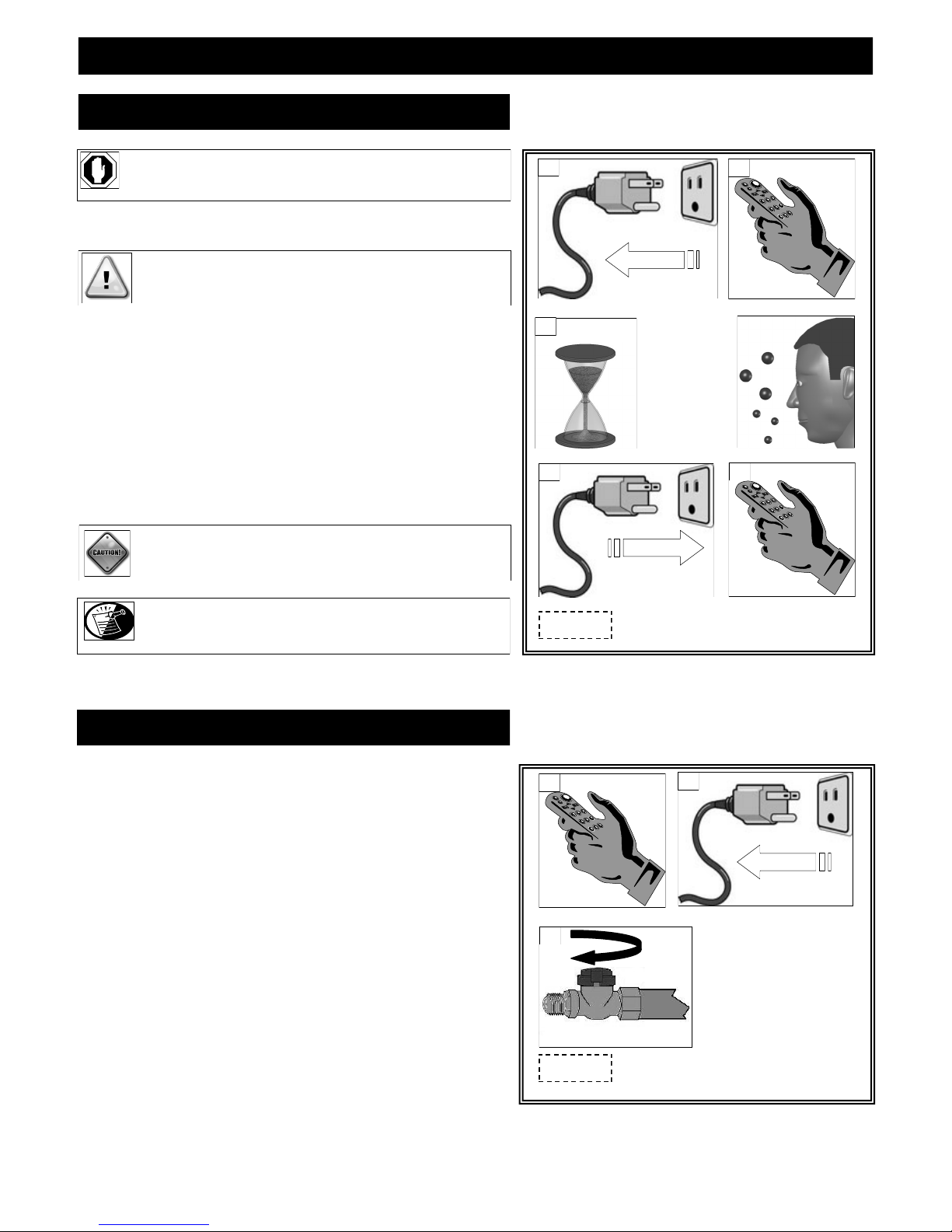
911-IPI LIGHTING AND SHUTDOWN (cont.)
LIGHTING
STOP! Read safety information on previous page and front
cover of this manual before continuing.
1. Turn off all electrical power to fireplace.
ATTENTION: This fireplace is equipped with an ignition device
which automatically lights the pilot.
DO NOT light the pilot by hand.
2. Press hand held remote MODE button to OFF.
3. Wait five (5) minutes to allow any gas that may have accumulated
inside firebox to escape. If you then smell gas, STOP! Follow safety information on front cover and on previous page of this
installation manual. If you don‘t smell gas, go to next step.
4. Turn ON all electrical power to fireplace.
5. Press hand held remote MODE button to ON.
CAUTION: If fireplace will not operate, follow instructions
TURNING OFF GAS TO FIREPLACE and call
your service technician or the gas supplier.
NOTE: When fireplace is initially lit, condensation will appear
on the glass; this is normal in all gas fireplaces and will
disappear after several minutes.
1
3
5 MINUTES
4
Figure 39a
2
Power OFF
OFF
5
Power ON
ON
TURNING OFF GAS TO FIREPLACE
1. Press hand held remote MODE button to OFF.
2. Turn OFF all electrical power to fireplace if service is required.
3. Turn manual shut-off valve to OFF.
1
OFF
3
Figure 39b
2
Power OFF
PAGE 39

PRESSURE TESTING (911-IPI)
IMPORTANT NOTICE: Pressure check taps for manifold (outgoing) and inlet (incoming) pressure have been incorporated into the
valve. The pressure tap marked OUT measures outgoing pressure and the pressure tap marked IN measures
incoming pressure. Follow instructions below for proper testing procedures.
NOTE: The appliance and its individual shutoff valve must be disconnected from the gas supply piping system during any
pressure testing of that system at pressures in excess of ½ psi.
NOTE: The appliance must be isolated from the gas supply piping system by closing its individual manual shut-off valve during
any pressure testing of the gas line at test pressures equal to or less than ½ psi (3.5 kPa).
INLET PRESSURE TEST:
1. Loosen inlet (‗IN‘) pressure tap screw (counter-clockwise).
2. Attach manometer using a 1/4‖ I.D. hose.
3. Light fireplace using hand held remote control. Note manometer reading.
4. Turn fireplace off using hand held remote control.
5. Disconnect hose and tighten screw (clockwise). Screw should be snug, do not over tighten.
6. Relight fireplace using hand held remote control. Reattach manometer to inlet pressure tap to verify it is completely sealed.
Manometer should read no pressure.
NOTE: If inlet pressure reading is too high or too low, contact the gas company. Only a qualified gas service technician should adjust
CAUTION: A LOW PRESSURE READING CAN CAUSE DELAYED IGNITION.
incoming gas pressure.
Outlet (Manifold) Pressure Screw
Figure 40a
Inlet Pressure Screw
PAGE 40

ERROR CODES (911-IPI only)
IGNITION SAFETY: Protection for Ignition System
Error Code: One beep every one second.
Description of Fault: Warns users if pilot is not successfully ignited in 60 seconds.
How to Clear: Press MODE button to OFF then to ON to re-attempt ignition.
What to Check:
Ensure gas supply is turned on.
Ensure black cap leads marked PILOT from module are plugged into PILOT connection on valve body.
Verify lead from igniter on pilot assembly is connected to ‗I‘ terminal on main control module. (Clicking sound will also be heard).
Verify lead from flame sensor on pilot assembly is connected to ‗S‘ terminal on main control module. (Pilot will light but main burner
will not. Pilot will extinguish after 60 seconds and error code will alarm).
Verify black ground lead is connected to tab extending from valve bracket.
SENSOR SAFETY: Protection for Flame Sensor
Error Code: Four beeps every one second.
Description of Fault: Warns users pilot flame senor detects a pilot flame already present when ignition sequence is initiated. This fault
will also occur if pilot flame senor on main control module is shorted to ground.
How to Clear: Press MODE button to OFF then to ON to re-attempt ignition.
What to Check:
Check if pilot flame is actually present when valve is turned OFF (if yes, replace valve).
Replace pilot assembly.
Replace module.
THERMAL SAFETY: Overheat Protection
Error Code: Four beeps every two seconds.
Description of Fault: Warns users that module‘s internal temperatures have exceeded 170˚ F (77˚C).
How to Clear: Module‘s internal temperatures must cool to below 160˚F (71˚C) and then press ON button.
What to Check:
Are modules located in an unapproved location. Move to cooler location.
COMMUNICATION SAFETY: Protection for Ignition System
Error Code: One beep every four seconds.
Description of Fault: Warns users the hand held remote and main control module are not communicating properly. This safety feature is
active in both manual and thermo modes. The remote control sends a communication safety signal every 15 minutes.
If the main control module does not receive this signal, it begins a 2-hour countdown. If no communication safety
signal is received at the end of this countdown, the system will enter communication safety shutdown which turns
system OFF and emits the error code.
What to Check:
Verify batteries in hand held remote control are new.
Ensure remote control is located within 20 ft. (6 m) of main control module.
Ensure remote control is not placed directly on top of or inside a metal enclosure as this can interfere with transmission.
PAGE 41

FINALIZING THE INSTALLATION
FLAME APPEARANCE:
Flame appearance is affected by several factors including altitude, venting configuration and fuel quality. Although the venturi setting has
been factory set, adjustments may be necessary for optimal performance and visual aesthetics.
When fireplace is first lit, the flames will be blue. Flames will gradually turn yellowish-orange during first 15 minutes of operation. If
flames remain blue, or become dark orange with evidence of sooting (black tips), the burner tube venturi may need adjustment.
WARNING: BURNER TUBE ADJUSTABLE VENTURI POSITIONING SHOULD ONLY BE PERFORMED BY A QUALIFIED
PROFESSIONAL SERVICE TECHNICIAN.
FACTORY SET BURNER TUBE VENTURI SETTINGS
(ADJUST AS NECESSARY FOR YOUR INSTALLATION)
NATURAL GAS LP (PROPANE) GAS
3/16” (5mm) open 5/8” (16mm)
BURNER TUBE VENTURI ADJUSTMENT GUIDELINES
VENTURI POSITION FLAME COLOR VENTURI ADJUSTMENT
Closed too far Dark orange flame with black tips Open venturi setting slightly
Open too far Blue flames Close venturi setting slightly
NOTE: If soot is present, check log positioning before adjusting burner venturi. Logs must not block burner ports.
IMPORTANT: SLIGHT ADJUSTMENTS TO BURNER VENTURI OPENING CREATE DRAMATIC RESULTS. ADJUST AT SLIGHT INCREMENTS
UNTIL DESIRED LOOK IS ACHIEVED. ALWAYS BURN FIREPLACE FOR AT LEAST 15 MINUTES AND ALLOW TIME TO COOL
BEFORE MAKING ANY FURTHER ADJUSTMENTS.
TO ADJUST VENTURI:
1. Remove glass frame assembly. Refer to page 9.
2. Remove log set.
3. Remove burner assembly. Refer to page 20.
4. Loosen screw on burner venturi and adjust as necessary. Tighten screw.
5. Reinstall all components previously removed.
6. Light fireplace and wait 15 minutes before determining if any further adjustments
are needed.
BURNER VENTURI
Figure 42a
PAGE 42

FINALIZING THE INSTALLATION
RESTRICTOR USAGE:
Turn fireplace on and allow to burn for 15 minutes.
If flames indicate there is excessive draft (flickering, short flames), a restrictor may be necessary.
If flames indicate insufficient draft (lifting or ghosting flames), a previously installed restrictor may need to be modified or removed.
WARNING: TO AVOID PROPERTY DAMAGE OR PERSONAL INJURY, ALLOW FIREPLACE AMPLE TIME TO COOL BEFORE M AKING ANY
ADJUSTMENTS AND / OR INSTALLATIONS.
RESTRICTOR TROUBLESHOOTING
FLAME APPEARANCE DRAFT PROBLEM RESTRICTOR SOLUTION
Short, flickering Excessive draft - not enough restriction Add restrictor
Lifting or ghosting* Insufficient draft - too much restriction Remove inner ring (s) on restrictor or
remove restrictor
* Improper venting installation may cause flames to lift or ―ghost‖ - a dangerous situation. Inspect flames after installation to ensure proper
performance. If determined that venting is correct, and the restrictor has been removed, yet flames are still lifting or ghosting, shut off gas
supply to fireplace and call a qualified service technician.
RESTRICTOR INSTALLATION / MODIFICATION (after termination completion):
If it is determined that a restrictor is needed or restrictor modification is required after termination is installed, access can be reached
through insert baffle. Please remove logs and refractory to avoid damaging these components.
1. Remove (2) nuts securing baffle. Remove baffle to expose venting.
2. Depending on your specific needs, determined by the chart above along with other factors, make necessary modifications.
3. If installation of a restrictor (included in components packet) is necessary, bend tabs on restrictor to approx. 80 degree angles to create
tension when inserted into the exhaust pipe on fireplace insert. Insert restrictor into 4‖ exhaust pipe with tabs pointing towards you.
4. If modification is necessary, remove restrictor by pulling it down and out of 4‖ exhaust pipe.
5. Reinstall baffle, secure with (2) nuts previously removed.
6. Reinstall refractory and log set.
7. Attach glass frame assembly and light fireplace. Wait 15 minutes before determining if any further modifications are necessary.
Remove baffle to expose venting.
Figure 43a
Large
PAGE 43
Remove tab (s) to
create small restrictor
Bend tabs to approx. 80
degree angles to create
tension to hold itself in
place when installed.

FINALIZING THE INSTALLATION
SEASONAL HEAT DUMP
This fireplace insert has been manufactured with a heat dump damper located at the inside top of firebox. This allows infinite
control over the amount of heat emitted into the living area without affecting flame height.
INSTALLER: Please install this fireplace insert with the heat dump in the closed position.
HOMEOWNER: This fireplace insert has been installed with the heat dump in the closed position and will operate at its peak efficiency
at this setting. The heat dump may be opened as much as necessary to maintain desired heat level.
CAUTION: Do not attempt to adjust heat dump opening if fireplace has been in operation. Allow ample time to cool or use appropriate
protection to avoid serious burns and / or property damage.
Remove glass frame assembly. Open or close heat dump as desired. Re-install glass frame assembly.
Figure 44a
Shown in closed position Shown in partial open position
PAGE 44
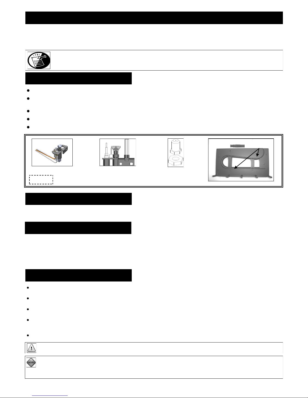
MAINTENANCE
The appliance is required to be inspected at least once a year by a professional service person.
The compartment below firebox (behind lower grill) must be cleaned at least once a year, more frequent cleaning may be required due to excessive
lint from carpeting, bedding materials, or other fibrous materials. It is imperative that the burner be cleaned once a year.
NOTE: INSTALLATION AND REPAIR SHOULD BE DONE ONLY BY QUALIFIED SERVICE PERSON. THE APPLIANCE SHOULD BE
INSPECTED BEFORE USE AND ANNUALLY BY A QUALIFIED SERVICE PERSON. MORE FREQUENT CLEANING MAY BE
REQUIRED DUE TO EXCESSIVE LINT FROM CARPETING, BEDDING MATERIALS, ETC. IT IS IMPERATIVE THAT CONTROL
CONTROL BOARD SYSTEM
Annual cleaning of the burner system is required.
The burner assembly may be removed for easier access. Refer to page 20 in this installation manual for complete instruction on removing &
reinstalling the burner assembly.
Visually check for blocked port holes, especially near the pilot. Blocked port holes may cause delayed ignition.
Reinstall burner assembly following instructions on page 20 of this installation manual.
Visually check pilot light and burner when in operation. The flames should be steady, not lifting or floating.
COMPARTMENTS, BURNERS AND CIRCULATION AIR PASSAGEWAYS OF THE APPLIANCE BE KEPT CLEAN .
Burner Ports
911-IPI Pilot
Figure 45a
911 / 911-RAD Pilot
Burner Orifice
FAN
The fan should be disconnected from electrical current, and cleaned (vacuumed) every six months. The bearings are sealed and require no oiling.
VENT SYSTEM
Annual examination of venting system by a qualified agency is required.
IF VENT-AIR INTAKE SYSTEM IS DISASSEMBLED FOR ANY REASON, RE-INSTALL PER INSTRUCTIONS PROVIDED WITH INITIAL
INSTALLATION.
The flow of combustion and ventilation air must not be obstructed.
GLASS CLEANING & REPLACEMENT
Clean glass only when cool and only with non-abrasive cleansers.
Do not operate this fireplace with glass/frame assembly removed, cracked or broken.
The glass assembly, part #700-08T, shall only be replaced as a complete unit, as supplied by Hussong Mfg. Co., Inc.
Replacement of glass & frame assembly, part #700-08T, must only be performed by a licensed or qualified service person.
DO NOT SUBSTITUTE MATERIALS.
Do not strike or slam glass door assembly.
IMPORTANT: ANY SAFETY SCREEN OR GUARD REMOVED FOR SERVICING MUST BE REPLACED PRIOR TO OPERATING THE APPLIANCE.
CAUTION: LABEL ALL WIRES PRIOR TO DISCONNECTION WHEN SERVICING CONTROLS. WIRING ERRORS CAN CAUSE IMPROPER AND
DANGEROUS OPERATION. VERIFY PROPER OPERATION AFTER SERVICING.
CAUTION: KEEP APPLIANCE AREA CLEAR OF COMBUSTIBLE MATERIALS, SUCH AS GASOLINE AND OTHER FLAMMABLE VAPORS AND LIQUIDS.
PAGE 45

911 / 911-RAD TROUBLESHOOTING
CAUTION: THE FOLLOWING MUST BE PERFORMED BY A QUALIFIED TECHNICIAN.
NO SPARK FROM ELECTRODE TO PILOT WHEN PIEZO BUTTON IS TRIGGERED.
A. Check wiring at back of piezo for proper connection.
B. Check wiring at electrode for proper connection.
C. Check position of electrode (1/8” (3 mm) between electrode and pilot). Readjust if necessary.
D. Look for arc below electrode and along electrode wire. Direct metal contact may cause an arc below electrode.
SPARK IGNITOR WILL NOT LIGHT AFTER REPEATED TRIGGERING OF PIEZO BUTTON.
A. No gas or low gas pressure.
Check remote shut off valves from fireplace. Usually there is a valve near the main. There may be more than (1) valve between
the fireplace and the main.
Low gas pressure can be caused by several situations such as a bent line, too narrow diameter pipe, or low line pressure. Consult
with plumber or gas supplier.
B. No LP in tank.
♦ Check LP (propane) tank. Refill if necessary.
PILOT WILL NOT STAY LIT AFTER CAREFULLY FOLLOWING LIGHTING INSTRUCTIONS.
A. Check that pilot flame impinges on thermocouple. Clean and / or adjust pilot for maximum flame impingement.
B. Ensure the thermocouple connection at gas valve is fully inserted and tight (hand tight plus 1/4 turn).
C. Thermocouple reading below 15 millivolts.
Disconnect thermocouple from valve, place one millivolt meter lead wire on end of thermocouple and other millivolt meter lead
wire on thermocouple‘s copper wire. Start pilot while holding valve knob in. If the millivolt reading is less than 15 millivolts,
replace thermocouple.
D. Thermopile not generating sufficient millivolts.
♦ Pilot flame must be enveloping thermopile. Adjust pilot flame if necessary.
♦ Check thermopile wire connections at valve. Tighten if necessary.
♦ Check thermopile with millivolt meter. Turn remote / thermostat / wall switch or ON/OFF switch to OFF. Turn valve knob to
PILOT position (pilot should remain lit). Take reading at THTP / TP terminals on gas valve. Reading should be 350 millivolts
minimum. Replace thermopile if reading falls below specified minimum.
PAGE 46

911 / 911-RAD TROUBLESHOOTING
BURNER WILL NOT LIGHT
A. Gas control knob not turned to ON.
B. ON/OFF switch not turned on.
C. Remote, wall switch or thermostat not turned ON.
D. Plugged main burner orifice.
E. Remote, wall switch ,thermostat or ON/ OFF switch wires defective.
Check wires for proper connections. Place jumper wires across terminal at switch. If burner lights, replace defective switch.
If switch checks ok, place jumper wires across switch wires on gas valve. If burner lights, wires are faulty or connections are bad.
FREQUENT PILOT OUTAGES
A. Pilot shield not installed.
B. Pilot flame too high or too low, causing pilot safety to drop out.
♦ Clean and adjust flame for maximum flame impingement on thermopile.
BURNER WON‟T STAY LIT
A. Thermopile wires loose at valve terminals.
♦ Tighten if necessary.
B. Thermopile wires ground out due to pinched wires.
♦ Free pinched wires if necessary.
C Refractory panel placement.
♦ Refractory panels must be tight against firebox walls. It may be necessary to secure panels with high-temp sealant, especially
around the intake duct.
MORE TROUBLESHOOTING ON FOLLOWING PAGE
PAGE 47

911 / 911-RAD TROUBLESHOOTING
PILOT AND BURNER EXTINGUISH WHILE IN OPERATION
A. No LP (propane) in tank.
♦ Check tank and refill if necessary.
B. Glass frame assembly not installed correctly.
♦ Refer to page 9 in this manual for proper glass frame assembly installment instructions.
C. Defective thermopile or thermocouple.
♦ Check thermopile and thermocouple for proper millivolts.
D. Improper pitch on horizontal vent.
♦ 1/4‖ (6 mm) rise per foot is required on horizontal venting.
E. Inner vent pipe leaking exhaust gases back into firebox.
♦ Check for leaks. Repair if necessary.
F. Improper vent cap installation.
♦ Check for proper vent cap installation. Maximum downward slope of horizontal vent cap is 1/4‖ (6 mm). Adjust if necessary.
♦ Check vent cap for blockage. Remove debris if necessary.
G. Excessive draft.
GLASS SOOTING
A. Improper log placement.
♦ Refer to log placement instructions on page 24 of this installation manual.
B. Improper venturi setting.
♦ Venturi may need to be opened slightly to allow more air into the gas mix.
C. Improper pitch on horizontal venting.
♦ 1/4‖ (6 mm) rise per foot is required on horizontal venting.
FLAME BURNS BLUE AND LIFTS OFF BURNER
A. Improper Venturi setting.
♦ Venturi may need to be closed slightly.
B. Improper vent cap installation.
♦ Check for proper vent cap installation.
C. Blockage or vent system leaks.
PAGE 48

911-IPI TROUBLESHOOTING
MAIN CONTROL MODULE WILL NOT LEARN TRANSMITTER
Ensure REMOTE/OFF switch on side of main control module is set to REMOTE.
Make sure batteries in both the hand held remote and backup battery pack are installed in the proper direction and are not drained.
Verify hand held remote indicates a signal is being sent. The LCD display should indicate ON or OFF depending on which button is
being pressed. The LED indicator should illuminate on wall transmitters and on/off transmitters. Buttons should be pressed and held
for 1 to 2 seconds to ensure a complete signal is sent.
Ensure 4-pin lead-set is securely connected from battery pack to main control module‘s AUX connection. If the A/C adapter is used,
check that leads from adapter are securely connected to POWER terminals on main control module.
Press and hold LEARN button on main control module for approximately 10 seconds to clear memory (you should hear a series of
beeps from the receiver), immediately press either the ON or OFF button on hand held remote (you should hear a series of beeps
indicating the transmitter code has been learned).
PILOT WILL NOT LIGHT / STAY LIT
Verify gas supply is turned on.
Verify main control module is receiving signal from hand held remote by listening for a beep from receiver when ON is pressed on
hand held remote. If you do not hear a beep, ensure main control module has learned the hand held remote. (See above).
Ensure black lead from pilot assembly igniter is securely connected to terminal labeled ‗I‘ and red lead from flame rectification
sensor is securely connected terminal labeled ‗S‘ on main control module.
Make sure black cap leads marked PILOT from main control module are securely connected to terminals labeled PILOT on valve
body.
Ensure black GROUND wire is securely connected to tab located next to ON/OFF toggle switch. A proper ground is essential to
spark igniter operation.
Make sure pilot flame is in contact with flame rectification sensor on pilot assembly. This valve is equipped with a pilot flame
adjustment screw. If pilot flame is too small it will not contact flame rectification sensor and will not complete the safety circuit.
Check continuity of pilot on valve. Remove wire connector. If there is no continuity on pin terminals, replace valve.
PILOT FLAME ALWAYS ON / WILL NOT EXTINGUISH
Ensure continuous pilot icon is not present in LCD screen. If icon is present, press PILOT button. This will de-activate the continuous
pilot feature and the icon will disappear from LCD screen.
PILOT BURNING BUT IGNITOR CONTINUES TO SPARK
Check that flame sensor is fully impinged by pilot flame. If needed, adjust pilot.
Check end-to-end continuity of sensor. If sensor has continuity, replace module.
PAGE 49

911-IPI TROUBLESHOOTING
MAIN FLAME WILL NOT LIGHT
Verify gas supply is turned on.
Ensure pilot flame will ignite. If not, see pilot flame troubleshooting on previous page.
Make sure white cap leads marked MAIN from module are securely connected to terminals marked MAIN on valve body.
Make certain pilot flame is in contact with flame rectification sensor on pilot assembly. This valve is equipped with a pilot flame
adjustment screw. If pilot flame is too small it will not contact flame rectification sensor and will not complete the safety circuit.
Ensure pilot flame is properly located to ignite main flame.
Does hand held remote show CP in the display? If yes, childproof is on. De-activate by pushing PROG/TIME & UP keys at same time
for more than 5 seconds.
Check continuity of main burner coil on gas valve. Remove wire connector. If there is no continuity on pin terminals, replace valve.
FLAME HEIGHT ADJUSTMENT NOT WORKING / WORKS BACKWARDS
Ensure ‗+‘ (white dotted wire) and ‗—‘ (black wire) leads from battery pack or module are securely connected to ‗+‘ (white dotted
wire) and ‗—‘ (black wire) leads from main control module (‘+‘ to ‗+‘, ‗—‘ to ‗—‘).
Check functionality with all transmitters to determine if there is an issue with the main control system or an individual transmitter. If
the issue is with an individual transmitter, make sure batteries in hand held remote and backup battery pack are installed properly and
are not drained.
ROOM TEMP. DISPLAYED ON HANDHELD REMOTE NOT CORRECT
Ensure transmitter was not recently stored in a different location (air-conditioned, heated) from that in which the hand held remote was
tested. It may take up to 3 hours for the temperature inside a packaged transmitter, and several minutes for an unpackaged transmitter
to equalize with room temperature.
FIREPLACE WILL NOT RESPOND IN “THERMO” MODE
Ensure hand held remote is within 20 ft. (6.096 m) operational range.
Make sure an ON or OFF command was not last sent from another transmitter. These commands will override thermal commands from
the handheld remote control. To return system to THERMO mode, press either ON or OFF on hand held remote, then press MODE
button to put system in THERMO mode. Press and hold SET button to change set temperature.
Verify set temperature on hand held remote is at least 2˚F (1˚C) above or below room temperature. The system will not react to
temperatures within 2˚F (1˚C) of set temperature.
PAGE 50

CONVERSION KIT INSTRUCTIONS (911 / 911-RAD only)
#OCK-S32A NAT GAS CONVERSION KIT / #OCK-S50A LP GAS CONVERSION KIT
WARNING: This conversion kit shall be installed by a qualified service agency in accordance with the manufacturers instructions and
all applicable codes and requirements of the authority having jurisdiction. If the information in these instructions is not
followed exactly, a fire, explosion or production of carbon monoxide may result, causing property damage, personal injury
complete until operation of the converted appliance is checked as specified in the instructions supplied with the kit. Refer to
appliance owner‟s manual or product data plate for proper inlet and manifold pressure adjustments and orifice sizing.
This kit includes: (1) Valve Conversion Instructions (1) Gas Pilot Injector (1) Gas Conversion Label
(1) Burner Orifice #32 NAT / #50 LP (1) Gas Label
(1) Pilot Orifice BL22N-NAT / BL14LP-LP (1) Pilot Conversion Instructions
PREPARE FIREPLACE:
1. Turn fireplace off by pushing in and turning gas control knob clockwise to OFF position.
2. Remove glass frame assembly*, logs*, and burner assembly* from fireplace insert.
or loss of life. The qualified service agency is responsible for proper installation of this kit. The installation is not proper and
ATTENTION: NATURAL GAS MODELS ONLY: BTU input rating may be increased to 40,000 BTU by replacing factory equipped
orifice with the #29 orifice included in components packet.
IMPORTANT: For high altitude installations, consult local gas distributor or authority having jurisdiction for proper rating methods.
WARNING: SHUT OFF GAS SUPPLY BEFORE DISCONNECTING ANY ELECTRICAL POWER.
LP
Figure 51a
NAT
PILOT ORIFICE
CONVERT PILOT ASSEMBLY:
1. Using a 7/16‖ wrench, loosen and remove pilot hood by turning counter-clockwise.
2. Remove pilot orifice located inside pilot housing. Install pilot orifice included with kit.
3. Re-attach pilot hood. Tighten with wrench, making sure hood is centered between thermopile and thermocouple.
REPLACE BURNER ORIFICE:
Remove existing orifice cap and replace with orifice cap included with kit, making sure to tighten cap securely.
CONVERT HI/LO REGULATOR ON GAS VALVE:
Follow instructions included with kit to convert gas valve.
COMPLETE THE CONVERSION:
1. Adjust venturi on burner assembly to by loosening screw, adjusting cap and retightening screw.
CORRECT SETTINGS: NAT: 3/16” (5mm) open LP: 5/8” (16mm) open
2. Re-install burner assembly into fireplace, checking to ensure burner venturi is properly seated over burner orifice.
3. Re-install pilot shield.
4. Re-install logs*.
5. Light pilot and turn burner on*.
6. Check for leaks at all connections, whether field or factory made.
7. Test both inlet and manifold pressures*.
* Refer to installation manual if necessary.
PAGE 51

CONVERSION KIT INSTRUCTIONS (911-IPI units only)
#OCK-A32N-I-911-PSE NAT GAS CONVERSION KIT / #OCK-A50L-I-911-PSE LP GAS CONVERSION KIT
WARNING: This conversion kit shall be installed by a qualified service agency in accordance with the manufacturers instructions and
all applicable codes and requirements of the authority having jurisdiction. If the information in these instructions is not
followed exactly, a fire, explosion or productions of carbon monoxide may result, causing property damage, personal injury
complete until operation of the converted appliance is checked as specified in the instructions supplied with the kit. Refer to
appliance owner‟s manual or product data plate for proper inlet and manifold pressure adjustments and orifice sizing.
Kit includes: (1) Gas Conversion Label (1) Burner Orifice: NAT #32 / LP #50 (1) Gas Type Label
(1) Pilot Orifice: NAT #.018 / LP #.012 (1) Low Limit Screw: NAT #0 / LP #50
PREPARE THE FIREPLACE:
1. Remove glass frame assembly*, logs*, and burner assembly* from fireplace insert.
REPLACE BURNER ORIFICE:
1. Remove burner by lifting front up and pulling towards you to release venturi from orifice.
2. Remove existing orifice cap. Replace with orifice cap included with kit, making sure to
or loss of life. The qualified service agency is responsible for proper installation of this kit. The installation is not proper and
WARNING: SHUT OFF GAS SUPPLY AND ELECTRICAL POWER TO FIREPLACE.
SHUT OFF GAS SUPPLY BEFORE DISCONNECTING ELECTRICAL POWER.
Figure 52a
BURNER ORIFICE
tighten cap securely.
Pilot hood nut
CONVERT PILOT ASSEMBLY:
1. Remove (2) screws securing pilot assembly to pilot bracket. Place 7/16‖ wrench on pilot
hood nut and 1/2‖ wrench onto pilot base nut, turn pilot hood nut counter-clockwise to
remove pilot hood.
2. Remove pilot orifice located inside pilot hood and replace with one included with kit.
3. Re-attach pilot hood. Tighten with wrenches, making sure pilot hood is positioned as
shown in Figure 52d.
4. Attach pilot assembly to pilot bracket with screws previously removed.
GAS TYPE CONVERSION:
Press and hold Learn Button on Main Control Module for 20 seconds (access hole on right hand
side of outer wrap). A beep will be heard letting you know the procedure has been completed.
If converting from NAT to LP gas: one (1) second long beep
If converting from LP to Nat gas: three (3) second long beep
CONVERT THE GAS CONTROL VALVE:
1. Remove cap covering the pressure regulator.
2. Press down on pressure regulator tube and rotate 90˚. The shaft should pop out and point to
chosen gas. Re-attach cap.
3. Remove low limit screw (above valve motor; see page 53). Replace with one included in
kit.
pilot base nut
Figure 52b
Pilot orifice:
Remove existing,
replace with one
included with kit
Figure 52c
Sensor
Align
Figure 52d
pilot bracket
Hood outlet
PRESSURE REGULATOR CAP
Figure 52e
PAGE 52
NAT. SETTING
L.P. SETTING

CONVERSION KIT INSTRUCTIONS (911-IPI units only)
COMPLETE THE CONVERSION:
1. Adjust burner tube venturi to correct setting by loosening screw, adjusting cap and retightening screw.
CORRECT SETTINGS: NAT: 3/16” (5mm) open LP: 5/8” (16mm) open
1. Re-install burner into fireplace, checking to ensure burner venturi is properly seated over burner orifice.
4. Re-install logs*.
5. Turn on gas and electrical supplies.
6. Check for leaks at all connections, whether field or factory made.
7. Test inlet pressure*. Visually check pilot flame. Flame should envelope top of flame sensor and extend onto burner far enough for
proper ignition. To Adjust pilot: Turn pilot adjustment screw clockwise to decrease or counter-clockwise to increase pilot flame.
8. Turn fireplace off.
9. Affix gas type sticker to label.
10. Re-install glass frame assembly*.
11. Verify proper ignition and operation of fireplace.
12. Complete and affix ‗Gas Conversion‘ label behind lower grill.
Low limit Screw
Figure 53a
Outlet (Manifold) Pressure Screw
Inlet Pressure Screw
Figure 53b
PAGE 53

REPLACEMENT PARTS LIST
Replacement parts are available through your local dealer. Contact them for availability and pricing.
911 / 911-RAD CONTROL BOARD AND PARTS
911-770 911 Control Board - Nat Gas 700-092 Millivolt Generator
911-771 911 Control Board - LP Gas
700-023 On/Off Rocker Switch
700-086A S.I.T. Valve - Natural Gas
700-087A S.I.T. Valve - LP Gas
700-064 Pilot Assembly - Nat Gas
700-064-1 Pilot Assembly - LP Gas
700-090 Piezo Igniter w/ Nut (no wire)
700-060 Flexible Pilot Tubing (Valve to Pilot)
911-035 Burner Tube
911-IPI BOARD SYSTEM AND PARTS
911-600-IPI 911-IPI Control Board - Nat Gas 700-165 #.012 IPI LP Gas Pilot Orifice
911-601-IPI 911-IPI Control Board - LP Gas
700-400-06 Main Control Module
700-404-911 911 IPI Valve - Natural
700-404-911-1 911 IPI Valve - LP
700-200 Pilot Assembly - Natural Gas
700-200-1 Pilot Assembly - LP Gas
700-800 8-PIN Primary Wire Harness: Primary Wire Harness
700-500 5-PIN Wire Harness: Main Module to Valve Step Motor
700-120 Extension Module
700-401 4-PIN Wire Harness: Control Module to Extension Module
700-750 7.5 Volt Adaptor
700-208 IPI Remote Control
700-164 #.018 IPI NAT. Gas Pilot Orifice
LOG SET
932-500A 8 pc. Log Set
AD AD Log
AG AG Log
HB HB Log
BI BI Log
M M Log
C C Log
AJ AJ Log
900-REMB Rock Wool Embers
911-028-IPI IPI Fan Kit
700-059 Thermocouple
700-203 Manual Shut-off Valve
700-213-B 18‖ Flexible Gas Line-Black
700-225-F Flexible Gas Line-Valve to Burner Connection
700-232 Natural Gas Orifice #32
700-250 LP Gas Orifice #50
OCK-S32A Natural Gas Conversion Kit
OCK-S50A LP Gas Conversion Kit
700-751 Battery Back-up with (4) AA Batteries
700-203 Manual Shut-off Valve
700-213 18‖ Flexible Gas Line-Black
700-226 Flexible Gas Line-Valve to Burner Connection
700-232 Natural Gas Orifice #32
700-250 NAT Gas Orifice #50
OCK-A32N-I-911-PSE Natural Gas Conversion Kit
OCK-A50L-I-911-PSE LP Gas Conversion Kit
911-035 Burner Tube
700-330 Nat. Gas Low Limit Screw #0
700-350 LP Gas Low Limit Screw #50
700-752 Pilot Igniter (with wire)
700-753 Pilot Flame Sensor (with wire)
911-G900 Back / Sides Refractory Panels - 3pc.
911-G900B Back Refractory Panel (only)
911-G900S Side Refractory Panel (1side only)
911-005 Replacement Valance - only
900-006 1-1/8‖ Glass Gasket w/ Adhesive
700-08T 12‖ x 27‖ Glass with Gasket
911-028 Fan Kit
REFRACTORY PANELS (Sandstone)
GLASS & GLASS GASKET
FAN ASSEMBLIES
*Consult your dealer for information on optional accessories available for this fireplace.
This appliance tested & certified by:
OMNI - Test Laboratories, Inc.
13327 NE Airport Way
Portland, Oregon 97230
Model #911 / #911-RAD / #911-IPI
www.kozyheat.com
PAGE 54
Manufactured by:
Hussong Mfg. Co., Inc.
204 Industrial Park Drive
Lakefield, Minnesota 56150
507-662-6641

LIMITED WARRANTY
PAGE 55

LIFETIME WARRANTY
PAGE 56
 Loading...