

kozy heat ALPHA-36S Installation And Operation Manual
HUSSONG MANUFACTURING CO., INC.
ALPHA-36S
OMNI-Test
Laboratories, Inc.
Model #ALP-36S
Direct Vent Gas Fireplace
Installation and
Operation Manual
WARNING:
FIRE OR EXPLOSION HAZARD
Failure to follow safety warnings exactly
could result in serious injury, death, or
property damage.
ͷ Do not store or use gasoline or other
ammable vapors and liquids in the
vicinity of this or any other appliance.
ͷ WHAT TO DO IF YOU SMELL GAS
• Do not try to light any appliance.
• Do not touch any electrical switch; do
not use any phone in your building.
• Leave the building immediately.
• Immediately call your gas supplier from
a neighbor’s phone. Follow the gas
supplier’s instructions.
• If you cannot reach your gas supplier,
call the re department.
ͷ Installation and service must be performed
by a qualied installer, service agency or
the gas supplier.
Tested &
Listed By
C US
Portland
Oregon USA
This appliance may be installed in
an aftermarket, permanently located,
manufactured home (USA only) or mobile
home, where not prohibited by local codes.
This appliance is only for use with the type
of gas indicated on the rating plate. This
appliance is not convertible for use with
other gases, unless a certied kit is used.
INSTALLER: Leave this manual with the appliance.
CONSUMER: Retain this manual for future reference.
Hussong Mfg. Co., Inc. • ALP-36S Report No: 0216GF037S • Rev. 01, February 2015
English and French installation manuals are
available through your local dealer. Visit our
website www.kozyheat.com or scan the QR
code for our mobile app.

Read this manual before installation or operating this appliance.
Please retain this owner’s manual for future reference.
CONGRATULATIONS!
We welcome you as a new owner of a Kozy Heat gas replace. Kozy Heat products are designed with superior components
and materials, and assembled by trained craftsmen who take pride in their work. To ensure you receive a quality product, the
burner and valve assembly are 100 percent test-red, and the complete replace is thoroughly inspected before packaging. Our
commitment to quality and customer satisfaction has remained the same for over 30 years. We offer a complete line of gas and
wood replaces, along with stylish accessories to complement any decor. Adding a replace is one of the best ways to increase
the value of your home, and we are proud to offer a network of dealers throughout the country to help make your experience
everything you imagine. We pride ourselves in being dedicated not only to functionality and reliability, but also customer
safety. We offer our continual support and guidance to help you achieve the maximum benet and enjoyment from your Kozy
Heat gas replace.
Jim Hussong
President
Homeowner Reference Information
We recommend you record the following information:
Model Name: ___________________________________________
Serial Number: __________________________________________
Dealership Purchased from: _______________________________
Notes: _____________________________________________________________________________________________________________
____________________________________________________________________________________________________________________
____________________________________________________________________________________________________________________
____________________________________________________________________________________________________________________
____________________________________________________________________________________________________________________
Date purchased/installed: _________________________________
Location of fireplace: _____________________________________
Dealer phone: ___________________________________________
Dudley Hussong
Board Chairman
HOMEOWNER REFERENCE 3


TABLE OF CONTENTS
TABLE OF CONTENTS ................................................................... 5
1.0 INTRODUCTION ......................................................................7
1.1 Appliance Certification .................................................................. 7
1.2 Requirements for the Commonwealth of Massachusetts ......7
2.0 SPECIFICATIONS .................................................................... 8
2.1 Appliance Components ................................................................8
2.2 Heating Specifications .................................................................. 8
2.3 Appliance Dimensions ..................................................................9
2.4 Safety Barrier Dimensions ...........................................................10
3.0 FRAMING ................................................................................. 11
3.1 Appliance Placement Considerations ........................................ 11
3.2 Stand-off Assembly and Installation ...........................................11
3.3 Clearances to Combustibles ....................................................... 12
3.4 Wall Enclosure Rough Opening .................................................. 13
3.5 Recess Construction .....................................................................14
3.6 Floor Support and Protection ...................................................... 15
3.7 Vent Termination Framing .............................................................15
4.0 #970 HEAT DUCT KIT ............................................................ 16
4.1 Kit Components .............................................................................. 16
4.2 Specifications ................................................................................. 16
4.3 Attach Heat Duct to Fireplace .....................................................17
4.4 Install Register Mounting Frame and Junction Box ................17
4.5 Install and Wire Fan Assembly .................................................... 17
4.6 Run and Secure Duct Pipe .......................................................... 18
4.7 Complete the Installation .............................................................. 18
4.8 Operating Instructions .................................................................. 18
4.9 Maintenance ...................................................................................18
5.0 FACING AND FINISHING ........................................................ 19
5.1 Nailing Flange Assembly and Installation ................................. 19
5.2 Mantel Requirements ....................................................................20
5.3 Facing Material Requirements .....................................................21
6.0 GAS LINE CONNECTION .......................................................22
6.1 Gas Conversion (sold separately) .............................................. 22
6.2 Gas Line Installation ...................................................................... 22
7.0 TERMINATION LOCATIONS ...................................................23
7.1 Vertical Vent Cap Termination .....................................................23
7.2 Minimum Termination Clearances ...............................................24
8.0 VENTING .................................................................................. 25
8.1 Approved 5” x 8” Vent Systems ..................................................25
8.2 Venting Requirements ...................................................................25
8.3 Use of Elbows ................................................................................. 25
8.4 Restrictor Assembly and Installation .........................................25
8.5 Vertical Terminations .....................................................................26
8.6 Combination Venting ..................................................................... 27
8.7 #800-1 Series Direct Vent Termination Kit(s) ..........................29
8.8 Horizontal Vent Heat Shield Installation ....................................30
9.0 FIREPLACE SETUP ................................................................. 31
9.1 Hearth Plate and Component Access Doors ..........................31
9.2 Glass Frame Assembly ................................................................. 31
9.3 Light Kit ............................................................................................ 31
9.4 #AL36-500 Log Set Installation .................................................. 32
9.5 Firebox Liner Kit Installation ........................................................ 33
10.0 ELECTRICAL INFORMATION .............................................. 34
10.1 Electrical Specifications ............................................................. 34
10.2 Wiring Requirements ...................................................................34
11.0 OPERATING INSTRUCTIONS .............................................. 35
11.1 Setup Proflame 2 IFC Module ................................................... 36
11.2 Initialize the Control System ......................................................36
11.3 Reset the System for Manual Operation .................................36
11.4 Automatic Safety Restart ............................................................36
11.5 Backup Battery Operation ........................................................ 36
11.6 IFC Module Ignition Sequence ................................................. 37
11.7 Additional Diagnostic Information ............................................. 37
11.8 Remote Control Operation ........................................................ 38
12.0 ADJUSTMENT ....................................................................... 41
12.1 Pressure Testing ..........................................................................41
12.2 Burner Flame Adjustments ........................................................42
13.0 TROUBLESHOOTING ........................................................... 44
14.0 MAINTENANCE ..................................................................... 46
14.1 Burner and Pilot System ............................................................ 46
14.2 Fans ................................................................................................46
14.3 Vent System ..................................................................................46
14.4 Glass Assembly ........................................................................... 46
15.0 REPLACEMENT PARTS LIST ............................................... 47
LIMITED WARRANTY ..................................................................... 49
LIFETIME WARRANTY ...................................................................51
TABLE OF CONTENTS 5


1.0 INTRODUCTION
1.1 Appliance Certification
Laboratory: OMNI-Test Laboratories in Portland, Oregon
Standards:
ANSI Z21.88-2014/CSA 2.33-2014, Vented Gas Fireplace Heaters
CGA 2.17-M91 (R2009) , Gas-Fired Appliances for Use at High
Altitudes
CSA P.4.1-2009, Testing Method for Measuring Annual Fireplace
Efficiency
This installation must conform with local codes, or in the absence
of local codes, with the National Fuel Gas Code, ANSI Z223.1/
NFPA 54, or the Natural Gas and Propane Installation Code, CSA
B149.1.
1.2 Requirements for the
Commonwealth of Massachusetts
The following requirements reference various Massachusetts
and national codes not contained in this manual.
For all sidewall horizontally vented gas fueled equipment installed
in every dwelling, building or structure used in whole or in part
for residential purposes, including those owned or operated
by the Commonwealth and where the side wall exhaust vent
termination is less than (7) feet above finished grade in the area
of the venting, including but not limited to decks and porches, the
following requirements shall be satisfied:
1.2.1 Installation of Carbon
Monoxide Detectors
At time of installation of side wall horizontally vented gas fueled
equipment, the installing plumber or gas-fitter shall observe that
a hard wired carbon monoxide detector with an alarm and battery
back-up is installed on the floor level where the gas equipment is
to be installed. In addition, the installing plumber or gas-fitter shall
observe that a battery operated or hard wired carbon monoxide
detector is installed on each additional level of the dwelling,
building or structure served by the side wall horizontal vented gas
fueled equipment. It shall be the responsibility of the property
owner to secure the services of qualified licensed professionals
for the installation of hard wired carbon monoxide detectors.
In the event that the side wall horizontally vented gas fueled
equipment is installed in a crawl space or attic, the hard wired
carbon monoxide detector with alarm and battery back-up may
be installed on the next adjacent floor level. In the event that
the requirements of this subdivision can not be met at the time
of completion of installation, the owner shall have a period of
thirty (30) days to comply with the above requirements; provided,
however, that during said thirty (30) day period, a battery
operated carbon monoxide detector with an alarm shall be
installed.
1.2.2 Approved Carbon Monoxide Detectors
Each carbon monoxide detector as required in accordance with
the above provisions shall comply with NFPA 720 and be ANSI/
UL 2034 listed and IAS certified.
for the horizontally vented gas fueled heating appliance or
equipment. The sign shall read, in print no less the one-half inch
(½) in size, “GAS VENT DIRECTLY BELOW. KEEP CLEAR OF ALL
OBSTRUCTIONS”.
1.2.4 Inspection
The state or local gas inspector of the side wall horizontally
vented gas fueled equipment shall not approve the installation
unless, upon inspection, the inspector observes carbon monoxide
detectors and signage installed in accordance with the provisions
of 248 CMR 5.08 (2) (a) 1 through 4.
1.2.5 Exemptions
The following equipment is exempt from 248 CMR 5.08 (2) (a) 1
through 4: The equipment listed in Chapter 10 entitled “Equipment
Not Required To Be Vented” in the most current edition of NFPA
54 as adopted by the Board; and Product Approved side wall
horizontally vented gas fueled equipment installed in a room or
structure separate from the dwelling, building or structure used in
whole or in part for residential purposes.
1.2.6 Manufacturer Requirements
1.2.6.1 Gas Equipment Venting System Provided
When the manufacturer of Product Approved side wall horizontally
vented gas equipment provides a venting system design or
venting system components with the equipment, the instructions
provided by the manufacturer for installation of the equipment and
the venting system shall include:
• Detailed instructions for the installation of the venting system
design or the venting system components; and
• A complete parts list for the venting system design or venting
system.
1.2.7 Gas Equipment Venting
System NOT Provided
When the manufacturer of Product Approved side wall horizontally
vented gas equipment does not provide the parts for venting the
flue gases, but identifies “special venting systems”, the following
requirements shall be satisfied by the manufacturer:
• The referenced “special venting systems” instructions shall
be included with the appliance or equipment installation
instructions and;
• The “special venting systems” shall be Product Approved by
the Board, and the instructions for that system shall include a
parts list and detailed installation instructions.
A copy of all installation instructions for all Product Approved
side wall horizontally vented gas fueled equipment, all venting
instructions, all parts lists for venting instructions, and/or all
venting design instructions shall remain with the appliance or
equipment at the completion of the installation.
1.2.3 Signage
A metal or plastic identification plate shall be permanently
mounted to the exterior of the building at a minimum of eight (8)
feet above grade directly in line with the exhaust vent terminal
INTRODUCTION 7
2.0 SPECIFICATIONS
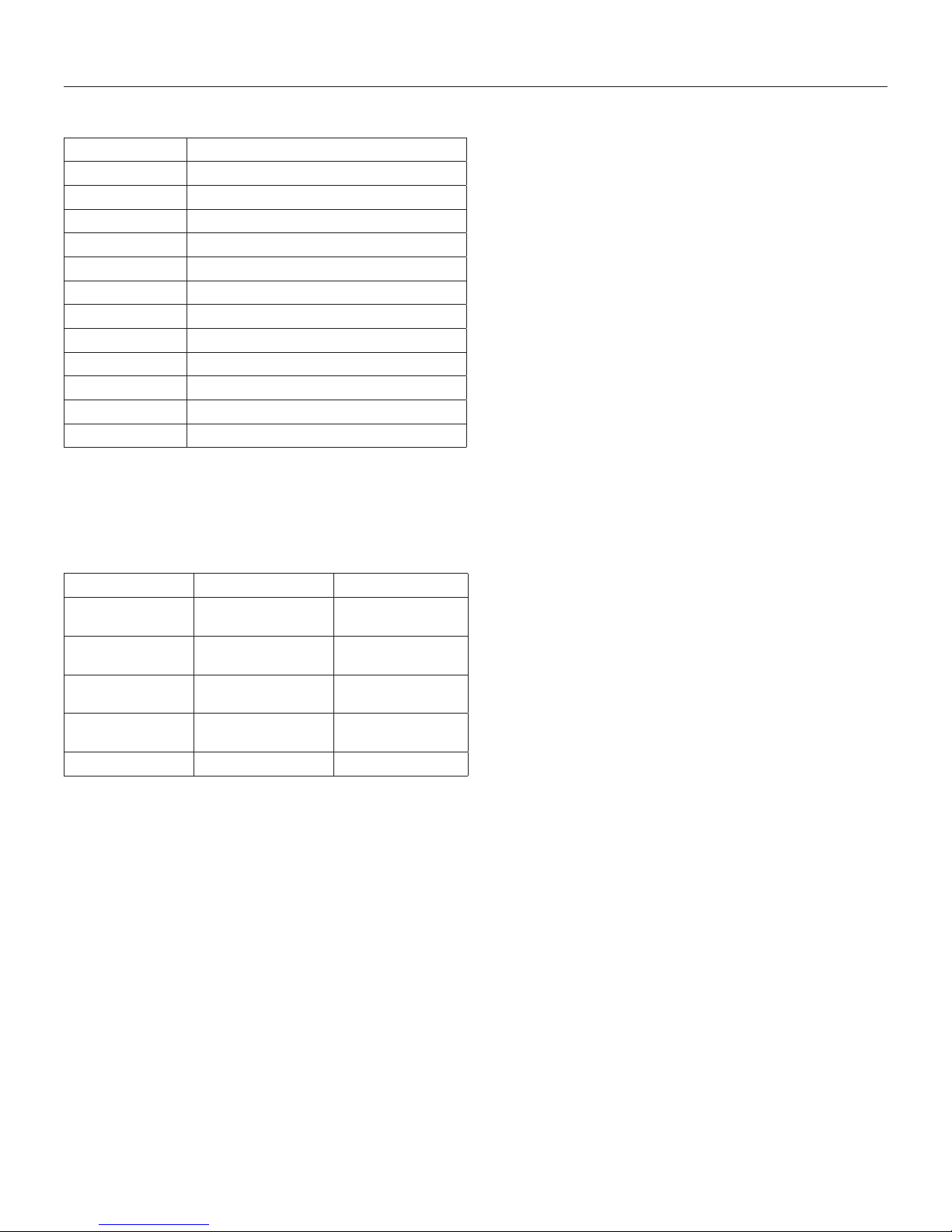
2.1 Appliance Components
Part Number Description
AL36-L-150 Control Board Assembly
700-203 Manual Gas Shut-off Valve
AL36-L-135 Burner Assembly
AL36-HP Hearth Plate
AL36-500 Log Package
AL36-CAD Component Access Doors
AL36--057T Glass Frame Assembly
AL36-LKT Light Kit
AL36-028 Fan Kit (2) - 75 CFM
600-002 Double Receptacle Assembly
700-408 Remote Control
942-085 5 in (127 mm) Restrictor Plate
2.1.1 Additional Components Required
Refer to Section 8.0 Venting on page 8, for approved vent
systems.
2.2 Heating Specifications
Natural Gas LP Gas
Maximum
Input Rating
Minimum
Input Rating
Manifold Pressure
(High)
Manifold Pressure
(Low)
Orifice Size (DMS) #29 #49
2.2.1 Altitude Adjustment
This appliance may be installed at higher altitudes. Please refer
to National Fuel Gas Code ANSI Z223.1/NFPA 54, CSA-B149.1
Natural Gas and Propane Installation Code, local authorities,
or codes having jurisdiction in you area regarding derate
guidelines.
2.2.1.1 US Installations
Refer to the American Gas Association guidelines for the gas
designed appliances derating method. For elevations above 2,000
ft (610 m) , input ratings are to be reduced by 4% for each 1,000 ft
(305 m) above sea level.
48,000 Btu/h
(14.07 kW)
24,000 Btu/h
(7.03 kW)
3.8” WC
(0.95 kPa)
1.1” WC
(0.27 kPa)
48,000 Btu/h
(14.07 kW)
24,000 Btu/h
(7.03 kW)
11” WC
(2.74 kPa)
2.9” WC
(.72 kPa)
2.2.1.2 Canadian Installations
When the appliance is installed at elevations above 4,500 ft (1,372
m), the certified high altitude rating shall be reduced at the rate of
4% for each additional 1,000 ft (305 m).
8 SPECIFICATIONS
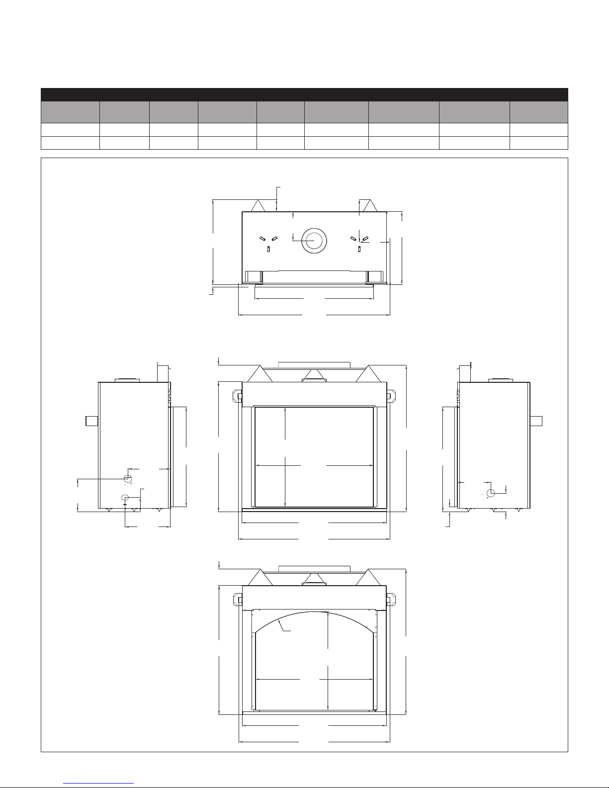
2.3 Appliance Dimensions
Table 2.1, Physical Dimensions
Description Height Width Back Width Depth Opening Width
Glass Frame
Height
Stand-off Height
Inches 41-11/16 46-1/2 46-1/2 23-3/8 38-1/4 32 5-5/16 9-3/8
Millimeters 1059 1182 1182 593 972 813 135 238
TOP
3⁄”
(99mm)
¾”
13
(349mm)
¾”
9
(248mm)
23
⁄”
(593mm)
27
¼”
(692mm)
⁄”
9
(99mm)
Back to Vent
Center
10
⁄”
(268mm)
3/4”
(19mm)
38
¼”
(972mm)
48
¾”
(1238mm)
LEFT RIGHTFRONT
⁄”
5
(135mm)
⁄”
⁄”
13
(347mm)
⁄”
4
(115mm)
14
⁄”
(370mm)
32
⁄”
(814mm)
41
(1059mm)
5
⁄”
(135mm)
⁄”
32
(814mm)
¼”
38
(972mm)
46
½”
(1182mm)
48
¾”
(1238mm)
47”
(1194mm)
33
(853mm)
1
½”
(38mm)
⁄”
¾”
10
(273mm)
5
⁄”
(151mm)
Figure 2.1, Alpha-36 Unit Dimensions
41
⁄”
(1059mm)
R30”
(761mm)
¼”
38
(972mm)
½”
46
(1182mm)
48
¾”
(1238mm)
31
¾”
(806mm)
47”
(1194mm)
SPECIFICATIONS 9
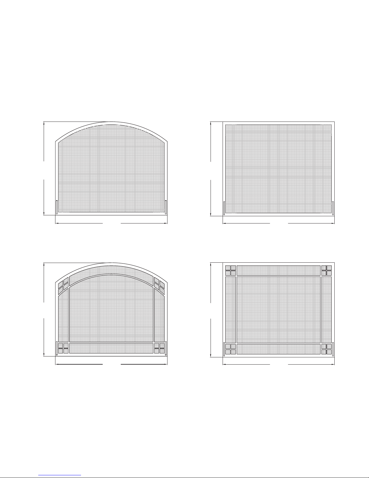
2.4 Safety Barrier Dimensions
WARNING: A barrier designed to reduce the risk of burns from
the hot viewing glass is provided with this appliance and shall
be installed for the protection of children and other at-risk
individuals.
If the barrier becomes damaged, the barrier shall be replaced
with Hussong Mfg.’s barriers for this appliance. Only doors
certified with the appliance shall be used.
2.4.1 Safety Barrier Installation
For models #AL36A-DSFS, #AL36A-MSFS, #AL36R-DSFS,
#AL36R-MSFS
1. Locate (2) magnets on the upper trim and (2) magnets on the
hearth plate.
2. Center the screen front inside the firebox and attach the
screen front to magnets.
3. To remove safety screen, detach from magnets.
31⁄”
(801mm)
⁄”
31
(801mm)
¾”
37
(957mm)
AL36A-DSFS
⁄”
31
(809mm)
⁄”
31
(809mm)
37¾”
(957mm)
AL36R-DSFS
37
¾”
(957mm)
AL36A-MSFS
10 SPECIFICATIONS
37
¾”
(957mm)
AL36R-MSFS
3.0 FRAMING
3.1 Appliance Placement
Considerations
WARNING: Due to high temperatures, the appliance should be
located out of traffic and away from furniture and draperies.
FIRE HAZARD : Do NOT install this appliance directly on
carpeting, vinyl, or any other combustible material other than
wood.
• This appliance must be installed on a level surface capable
of supporting the fireplace and venting. If possible, place the
fireplace in a position where the vent terminates between two
studs, eliminating the need for any additional framing.
• This fireplace may be installed in a bedroom.
• Please be aware of the large amount of heat this fireplace will
produce when determining a location.
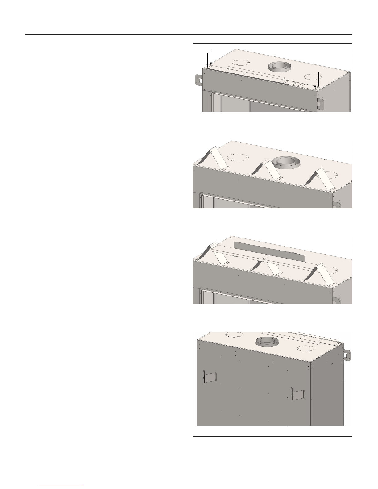
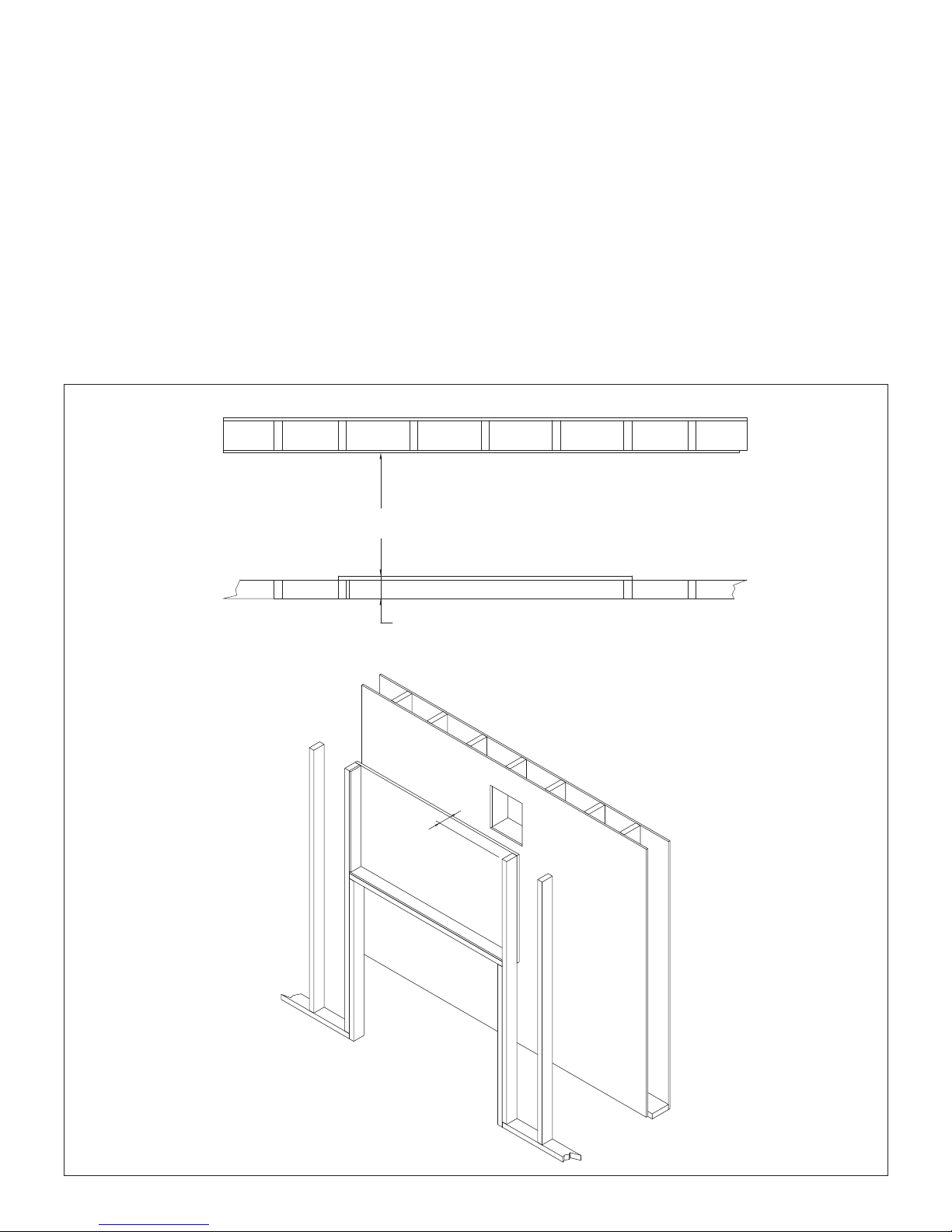
3.2 Stand-off Assembly and Installation
WARNING: The top stand-offs provide the 5-5/16” (135 mm)
minimum clearance to the header. Use only non-combustible
material in this area for the entire width of the fireplace. DO
NOT use wood, sheetrock, et cetera, in this zone.
Top stand-off brackets must be formed and attached prior to
positioning fireplace into framed opening.
1. Remove and save (4) screws securing stand-off heat shields
and stand-off brackets on top of the fireplace.
2. Form each stop stand-off bracket by pending at perforations,
as shown.
3. Align the holes in the formed top stand-offs with the holes in
the fireplace top. Secure with (4) screws previously removed
along with (8) screws provided in the fireplace components
packet.
4. Form stand-off heat shields as shown. The flange will face up
and to the back of the fireplace.
5. Align the stand-off heat shields with the holes in the top
stand-off brackets. Secure with (6) screws provided in the
fireplace components packet.
6. Remove and form the back stand-off brackets. Reattach
using (4) screws previously removed and (4) screws provided
in the components packet.
TOP STAND OFF BRACKETS AS SHIPPED
TOP STAND-OFF BRACKETS INSTALLED
STAND-OFF HEAT SHIELD INSTALLED
BACK STAND-OFFS INSTALLED
Figure 3.1, Stand-off Assembly and Installation
FRAMING 11
3.3 Clearances to Combustibles
Table 3.1, Minimum Appliance Clearances to Combustible Material
Top of unit face to framing 5-5/16 in 135 mm
From unit left and right side stand-offs 0 in 0 mm
From unit back stand-offs 0 in 0 mm
From bottom stand-offs 0 in 0 mm
Top of unit face to ceiling 30-5/16 in 770 mm
Side of finishing edge to adjacent sidewall 6 in 152 mm
Unit front to combustibles 36 in 914 mm
Mantel 9 in (229 mm) deep from fireplace enclosure floor 47 in 1194 mm
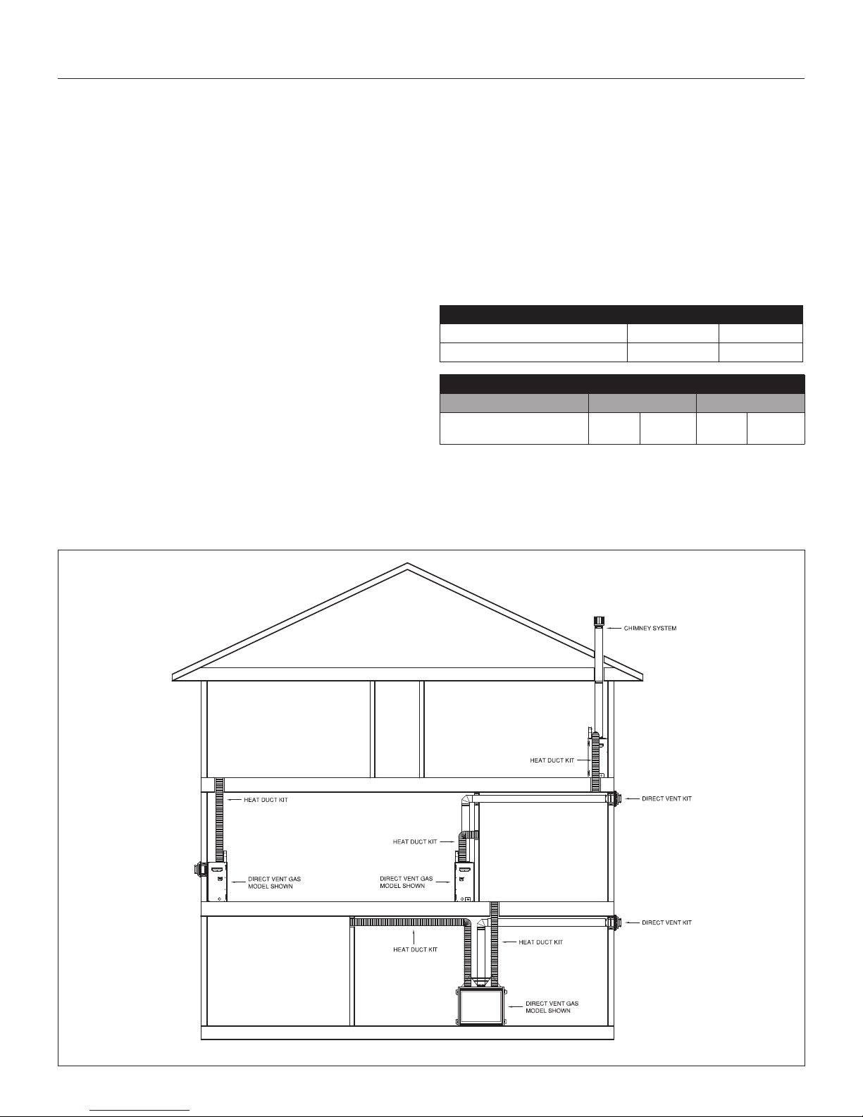
TYPICAL HORIZONTAL INSTALLATION TYPICAL VERTICAL INSTALLATION
Figure 3.2, Typical Installation Options
12 FRAMING
TYPICAL CORNER INSTALLATION
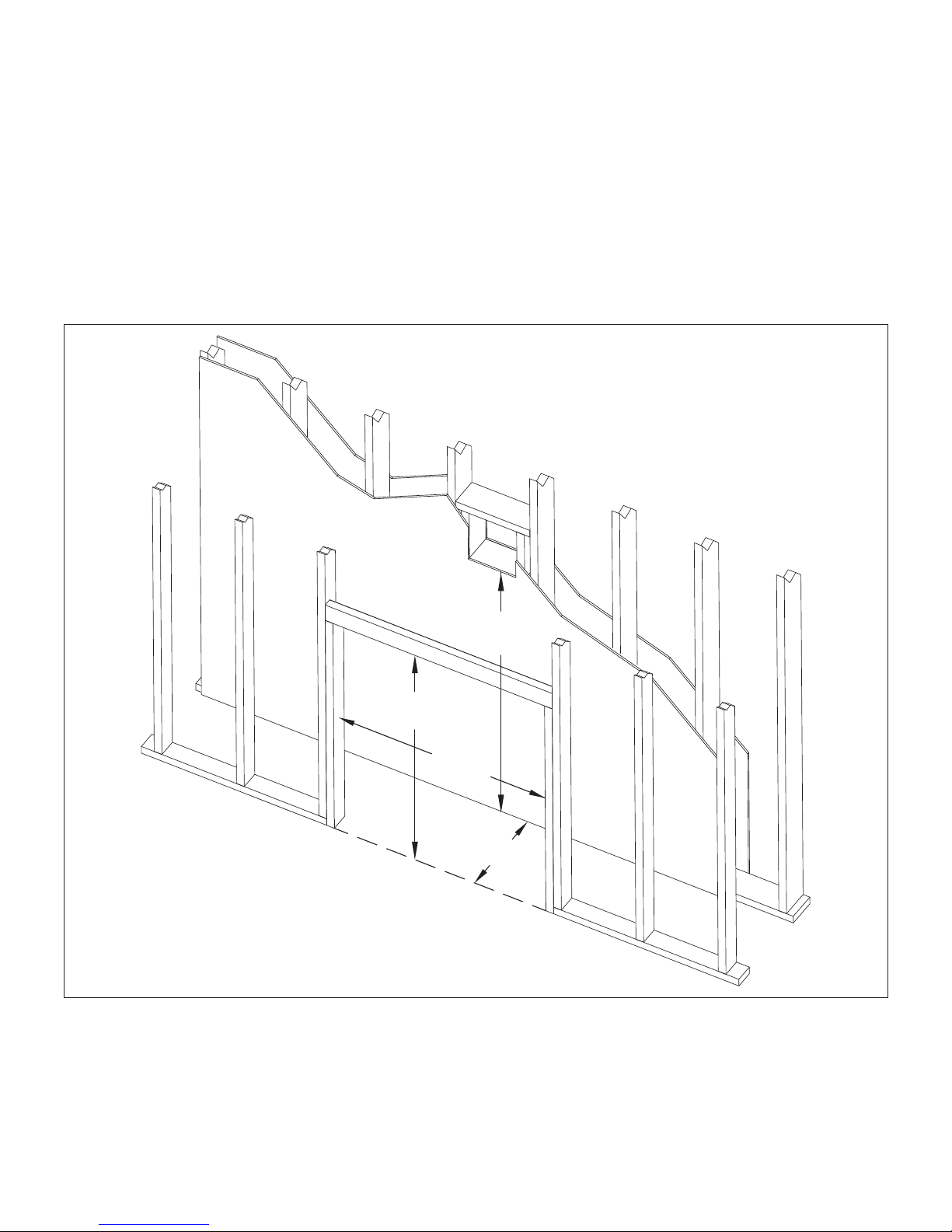
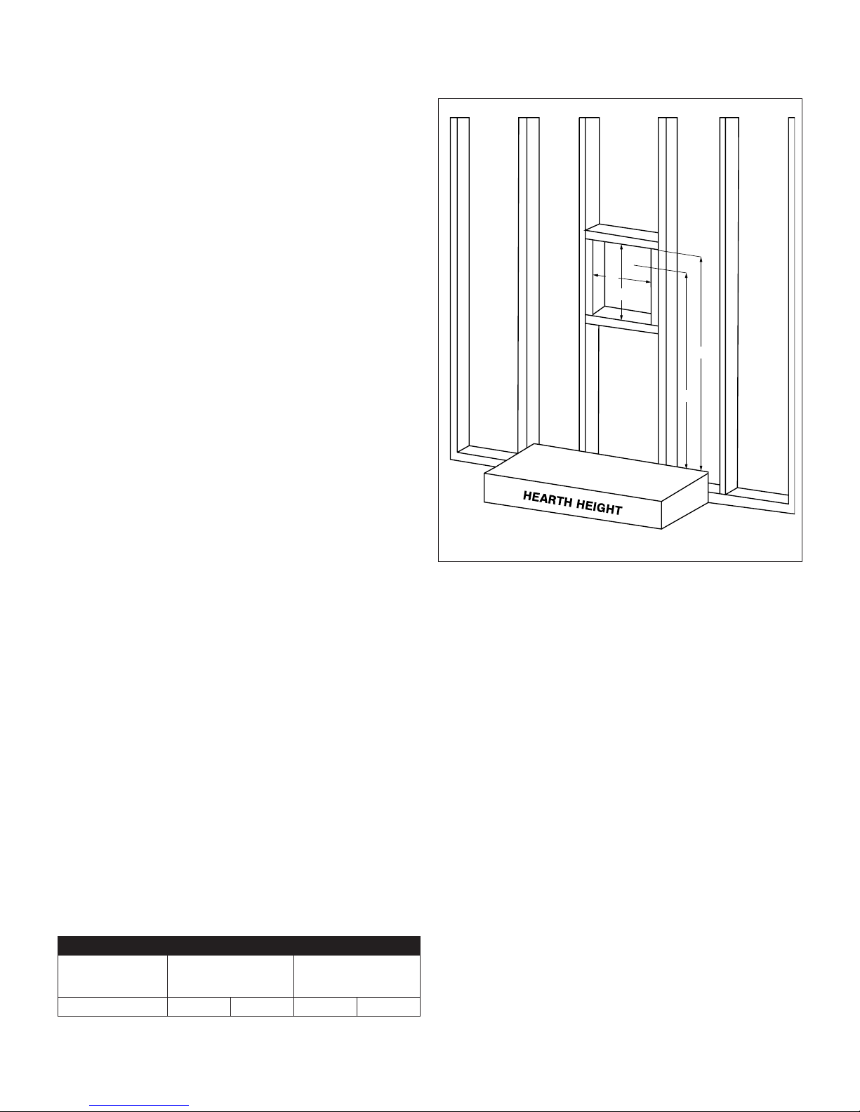
3.4 Wall Enclosure Rough Opening
WARNING: Provide adequate clearances around air openings
into the combustion chamber. Provide adequate clearance in
front of the fireplace for barrier removal, component access,
gas line installation, service access, etc.
• Framing dimensions should allow for wall covering thickness
and fireplace facing materials. If using a hearth, adjust the
rough opening size as necessary to maintain minimum
clearance requirements.
• If masonry is to be used (optional) , prepare the necessary
foundation for the masonry load. When masonry construction
is to be used, a lintel must be used over the top of the
appliance to support the additional weight.
• If installing the optional heat duct kit, please refer to Section
4.0 #970 Heat Duct Kit on page 16.
Figure 3.3, Finished Opening Dimensions
47”
(1194mm)
48
¾”
(1238mm)
⁄”
58
(1483mm)
27¼”
(692mm)
FRAMING 13
3.5 Recess Construction
WARNING: All clearances to venting must be maintained.
Mounting a television above a fireplace has become a common
practice. Television surface temperatures are affected by mantel
depth, ceiling heights, and wall and mantel construction material.
Most television manufacturers specify in their instructions that a
television should not be installed on, near, or above a heat source.
Television location rests solely on the homeowner. It is the
homeowner’s responsibility that the preferred TV mounting and
mantel design will not exceed the listed maximum operation
temperature of their electronic goods.
Tests performed determined that surface temperatures did
not exceed 150°F (66°C) when a 4¼ in (108mm) deep recess
is constructed above the fireplace. See illustrations below.
23”
(584mm)
¼”
4
(108mm)
4¼”
(108mm)
Figure 3.4, Recess Framing
14 FRAMING
3.6 Floor Support and Protection
• The fireplace must be placed directly on a wood or noncombustible surface (not linoleum or carpet) extending the
entire depth and width of the fireplace
• If this appliance is to be installed directly on carpeting, tile,
or other combustible material other than wood flooring,
this appliance shall be installed on a metal or wood panel
extending the full width and depth of the appliance.
• If the appliance is to be installed above floor level, a
solid, continuous platform must be constructed below the
appliance.
• Consider the height of hearth finish material (stone, brick,
et cetera) when building a fireplace platform. The bottom of
the fireplace must be level with finished hearth to allow for a
proper fit of the safety barriers.
• Build the hearth to desired size and height. If a hearth
extension is desired, combustible material may be used.
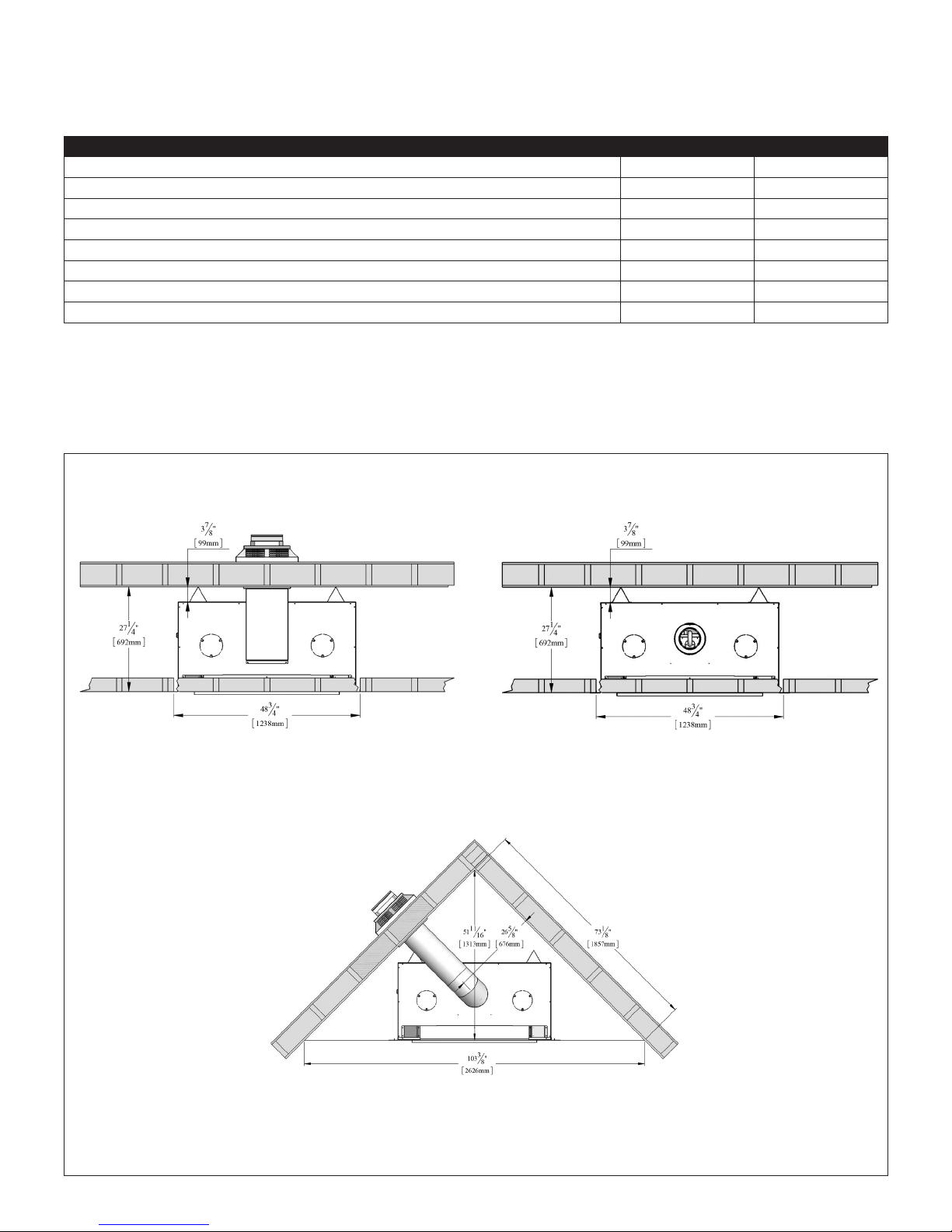
3.7 Vent Termination Framing
IMPORTANT: Vent cap location must be in compliance with
Section 6.2 Minimum Termination Clearances on page 21.
WARNING: DO NOT RECESS THE VENT CAP INTO WALL OR
SIDING.
3.7.1 Vertical Terminations
CAUTION: Cold air transfer area. The surround fireplace chase
must comply with all clearances as outlined in this manual,
and be constructed in compliance with local building codes.
Outside walls should be insulated to prevent cold air from
entering room.
• Follow vent pipe manufacturer’s installation instructions for
vertical terminations.
• A minimum of 1 in (25 mm) clearance on all sides of the
vertical vent pipe must be maintained.
W
H
B
A
Figure 3.5, Horizontal Vent Terminations
3.7.2 Horizontal Terminations
IMPORTANT: Horizontal vent sections require 1/4 in (6 mm)
rise for every 12 in (305 mm) of travel.
NOTE: Elbows listed with approved vent systems for this
appliance vary in vertical length. Please consult the vent
manufacturer’s instructions to determine the elbow dimension
used for installation. Adjust the wall pass -through rough opening
dimensions as necessary to maintain clearance requirements.
• Follow vent pipe manufacturer’s installation instructions for
vent installation.
• Rigid pipe vent systems require a minimum of 3 in (76 mm)
from the top surface of horizontal pipe, and 1 in (25 mm)
from the sides and bottom surfaces of horizontal pipe.
• Refer to Table 3.2 and Figure 3.5 for horizontal vent framing.
Table 3.2, NG & LPG - Minimum Horizontal Venting
Minimum Vertical
Rise
18 in (457mm)
Rigid Vent System 68 in 1.73 m 71 in 1.8 m
Vent Pipe Top (A) Framed Opening
Top (B)
FRAMING 15
4.0 #970 HEAT DUCT KIT
CAUTION : Read and follow instructions carefully prior to and
during the installation of the optional heat duct kit.
WARNING: Installation of this heat duct kit and its electrical
wiring must be performed by a qualified service person, and
must be in accordance with local codes, or in the absence of
local codes, with the National Electrical Code, ANSI/NFPA 70,
or the Canadian Electrical Code, CSA C22.1.
Do not substitute the flexible heat duct pipe with plastic vent
pipe.
4.1 Kit Components
NOTE: A junction box, cover, and hardware must be purchased
to mount the speed control.
(1) 6” (152 mm) diameter flexible heat
duct pipe, expandable to 20 ft. (6.10 m)
(1) Register mounting frame with collar (11) Sheet metal screws
(1) Register cover with screws (4) Sheet rock screws
(1) Duct collar (3) Flange nuts
(1) Fan assembly (1) Strapping cord
(1) Fan housing cover plate (3) Wire nuts
(1) Speed control mounting bracket (2) Fan wire connectors
(1) Speed control
(2) Mounting brackets
4.2 Specifications
• The appliance is manufactured with (2) heat duct knock-outs.
One, or both, may be utilized.
• The register mounting frame is designed to fit between 2” x
4” stud walls, 16 in (406mm) on center.
• An oval duct pipe (equivalent to 6 in [152 mm] round) can be
used in conjunction with the included 6 in (152 mm) diameter
flexible heat duct pipe, included with this kit. It must be
purchased from a HVAC supplier.
• Carefully plan location of duct pipe runs and register in
relation to fireplace.
Table 4.1, Heat Duct Clearances
From flexible duct to combustibles 0 in 0 mm
From air duct to ceiling 2 in 51 mm
Table 4.2, Heat Duct Vent runs
Vent Run Minimum Maximum
Any direction, including
downward
2 ft 609 mm 20 ft 6.1 mm
Figure 4.1
16 #970 HEAT DUCT KIT
 Loading...