

kozy heat ALP-36-L, ALP-36-G Installation Manual
INSTALLATION MANUAL
DIRECT VENT GAS FIREPLACE
English and French Inst allati on Manuals Ava il ab le Thr ou gh You r Loca l Deal er or Visit Our Web si te at ww w. ko zyhe at .c om
Les manuels d’installation en anglais et en français sont disponibles chez votre détaillant local ou en visitant notre site Web : www.kozyheat.com
IMPORTANT: This installation manual is to be used in conjunction with SUPPLEMENTAL
INSTALLATION AND HOMEOWNER INFORMATION MANUAL. Read both manuals before installing
and operating appliance.
INSTALLER: Leave this manual with the appliance.
CONSUMER: Retain this manual for future reference.
This appliance may be inst alled in an aftermarket perma nently loca ted,
manufactured home (USA only) or mobile home, where not prohibited by local codes.
This appliance is only for use with the type of gas indicated on the rating plate. This
appliance is not convertible for use with other gases, unless a certified kit is used.
WARNING: If the information in these instructions is not followed exactly, a fire
or explosion may result causing property damage, personal injury or loss of life.
—Do not store or use gasoline or other flammable vapors and liquids in the vicinity
of this or any other appliance.
WHAT TO DO IF YOU SMELL GAS:
◙ Do not try to light any appliance.
◙ Do not touch any electrical switch: do not use any phone in your building.
◙ Immediately call gas supplier from a neighbors phone. Follow the gas supplier
instructions.
◙ If you cannot reach your gas supplier, call the fire department.
— Installation and service must be performed by a qualified installer, service
agency or the gas supplier.
WARNING
HOT GLASS WILL CAUSE BURNS.
DO NOT TOUCH GLASS UNTIL COOLED.
NEVER ALLOW CHILDREN TO TOUCH GLASS.
Report No. 216-S-37b-6.5
JULY 2013
ALP-36-L-REV-04
www.kozyheat.com
INTRODUCTION
Read this manual before installing or operating this appliance.
Please retain this owner’s manual for future reference.
CONGRATULATIONS!
We welcome you as a new owner of a Kozy Heat gas fireplace. Kozy Heat products are
designed with superior components and materials and assembled by trained craftsmen who
take pride in their work. The burner and valve assembly are 100% test-fired and the complete
fireplace is thoroughly inspected before packaging to ensure that you receive a quality product.
Our commitment to quality and customer satisfaction have remained the same for over 30
years. We offer a complete line of gas and wood fireplaces, unique cabinets and stylish
accessories to compliment any décor. Adding a fireplace is one of the best ways to increase the
value of your home and we are proud to offer a network of dealers throughout the country to
help make your experience everything you imagine. We pride ourselves in being dedicated to
not only function and reliability, but customer safety as well. We offer our continual support
and guidance to help you achieve the maximum benefit and enjoyment from your Kozy Heat
gas fireplace.
Jim Hussong Dudley Hussong
President Board Chairman
Homeowner Reference Information
We recommend that you record the following information about your fireplace.
Model Name:______________________________ Date purchased/installed:_____________________________________
Serial Number:____________________________ Location on fireplace:________________________________________
Dealership purchased from:__________________ Dealer Phone:______________________________________________
Notes:_______________________________________________________________________________________________
____________________________________________________________________________________________________
____________________________________________________________________________________________________
1
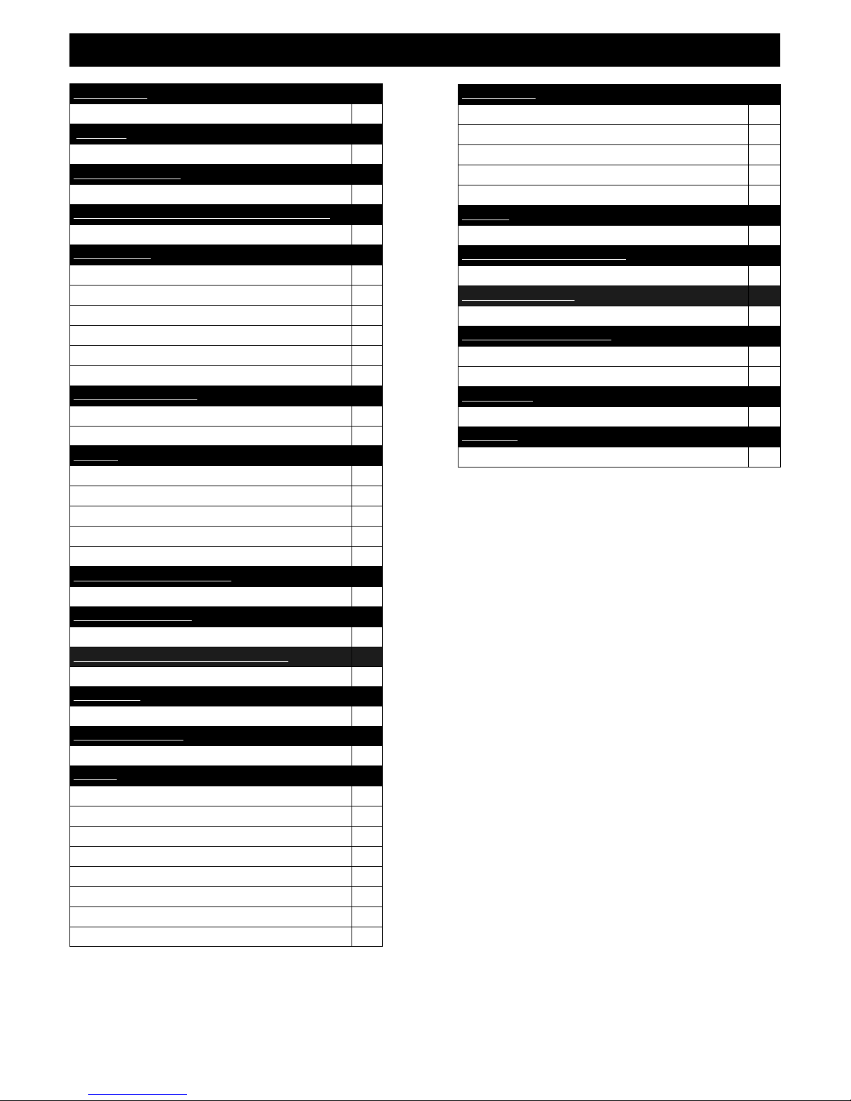
TABLE OF CONTENTS
INTRODUCTION
Introduction and Homeowner Reference Information 1
CONTENTS
Table of Contents 2
SAFETY INFORMATION
Safety Information 3
COMMONWEALTH OF MASSACHUSETTS INFORMATION
Commonwealth of Massachusetts Information 4
SPECIFICATIONS
Fireplace Dimensions 5
Clearances 5
Additional Components Required 6
Installation Overview 6
Placement Clearance Requirements 7
Television Positioning Considerations 7
FIREPLACE PREPARATION
Stand-off / Stand-off Heat Shield Assembly & Installation 8
Nailing Flange Assembly & Installation 9
FRAMING
Wall Enclosure Rough Opening 10
Minimum Finished Opening Dimensions 10-11
Vertical Terminations 11
Horizontal Terminations 11
Facing and Finishing 12
TYPICAL INSTALLATION OPTIONS
Typical Installation Options 13
MANTEL REQUIREMENTS
Mantel Requirements 14
HEARTH PLATE / COMPONENT ACCESS DOORS
Hearth Plate / Component Access Doors 15
GLASS FRAME
Glass Frame Assembly Removal / Installation 15
GAS LINE CONNECTION
Gas Line Connection 16
VENTING
Approved Venting 17
Restrictor 17
Elbows 17
Vertical Vent System Clearances 18
Vertical Minimum / Maximum 18
Horizontal Vent System Clearances 18
Horizontal Vent Heat Shield Installation Instructions 18
#800-WPT Wall Pass-Thru Installation 19
VENTING (cont.)
Horizontal Termination Minimum / Maximum 20
Horizontal & Vertical Combination Venting Illustrations 20
#800-1 Series Flex Vent Installation Instructions 21-22
Termination Vent Cap Location 23
Vent Termination Clearances 24
LIGHT KIT
Light Kit 25
FIREBOX LINER KIT INSTALLATION
Firebox Liner Kit Installation 26
LOG SET INSTALLATION
Log Set Installation 27
FINALIZING THE INSTALLATION
Burner Tube Adjustment / Troubleshooting 28
Restrictor Troubleshooting / Installation after Termination Completion 29
MAINTENANCE
Maintenance 30
WARRANTY
Warranty 31-32
2

SAFETY INFORMATION
This fireplace has been tested by OMNI-Test Laboratories, Portland, Oregon and complies with:
ANSI Z21.88-2009/CSA 2.33-2009, “Standard for Vented Gas Fireplace Heaters.”
CAN/CGA 2.17-M91 (R2009), “Gas-Fired Appliances for Use at High Altitudes”.
CAN/CSA P.4.1-09, “Testing Method for Measuring Annual Efficiency”.
This installation must conform with local codes, or in the absence of local codes, with the National Fuel Gas Code, ANSI Z223.1/NFPA 54,
or the Natural Gas and Propane Installation Code, CSA B149.1
The appliance, when installed, must be electrically grounded in accordance with local codes or, in the absence of local codes, wth the National
Electrical Code, ANSI/NFPA 70, or the Canadian Electrical Code, CSA C22.1.
Installation and repair should be done only by a qualified service person. The appliance should be inspected by a
qualified service person before use. Annual inspection by a qualified service person is required to maintain warranty.
More frequent cleaning may be required due to excessive lint from carpeting, bedding materials, etc. It is imperative
th a t con trol compa r t m e n t s, burners and c i r c ulation air pa s s a g e w a ys of the app l i a n c e b e kept cle a n .
If this appliance is installed directly on carpeting, tile or other combustible material other than wood flooring, the
appliance shall be installed on a metal or wood panel extending the full width and depth of the appliance.
Children and adults should be alerted to the hazards of high surface temperatures and should stay away to avoid burns
or clothing ignition.
Young children should be carefully supervised when they are in the same room as the appliance. Toddlers, young
children and others may be susceptible to accidental contact burns. A physical barrier is recommended if there are at
risk individuals in the house. To restrict access to a fireplace or stove, install an adjustable safety gate to keep toddlers ,
young children and other at risk individuals out of the room and away from hot surfaces.
Clothing or other flammable material should not be placed on or near the appliance.
Adequate accessibility clearances for servicing and proper operation must be maintained.
This appliance must not share or be connected to a chimney flue serving any other appliance.
Keep area around the appliance clear of combustible materials, gasoline and other flammable vapor and liquids.
The flow of combustion and ventilation air must not be obstructed.
Due to high temperatures the appliance should be located out of traffic and away from furniture and draperies.
The glass front or any part removed for servicing the appliance must be replaced prior to operating the appliance.
Work should be done by a qualified service technician.
Clean glass only when cool and only with non-abrasive cleansers.
WARNING: DO NOT OPERATE APPLIANCE WITH THE GLASS/FRAME ASSEMBLY REMOVED, CRACKED
OR BROKEN. REPLACEMENT OF THE GLASS SHOULD ONLY BE PERFORMED BY A LICENSED OR
QUALIFIED SERVICE PERSON .
The glass assembly, Part #AL36-057T, shall only be replaced as a complete unit, as supplied by Hussong Mfg. Co., Inc.
DO NOT SUBSTITUTE MATERIALS.
Do not strike or slam glass assembly.
Any safety screen or guard removed for servicing the appliance must be replaced prior to operating the appliance.
Under no circumstances should any solid fuel (wood, coal, paper or cardboard etc.) be used in this appliance.
Keep burner and control compartment clean.
Do not use this fireplace if any part has been under water. Immediately call a qualified service technician to inspect this
appliance and to replace any part of the control system and any gas control which has been under water.
3

COMMONWEALTH OF MASSACHUSETTS REQUIREMENTS
NOTE The following requirements reference various Massachusetts and national codes not contained in this manual.
For all sidewall horizontally vented gas fueled equipment installed in every dwelling, building or structure used in whole or in part for residential purposes,
including those owned or operated by the Commonwealth and where the side wall exhaust vent termination is less than (7) feet above finished grade in the
area of the venting, including but not limited to decks and porches, the following requirements shall be satisfied:
INSTALLATION OF CARBON MONOXIDE DETECTORS
At time of installation of side wall horizontally vented gas fueled equipment, the installing plumber or gas -fitter shall observe that a hard wired carbon
monoxide detector with an alarm and battery back-up is installed on the floor level where the gas equipment is to be installed. In addition, the installing
plumber or gas-fitter shall observe that a battery operated or hard wired carbon monoxide detector is installed on each additional level of the dwelling,
building or structure served by the side wall horizontal vented gas fueled equipment. It shall be the responsibility of the property owner to secure the services
of qualified licensed professionals for the installation of hard wired carbon monoxide detectors.
In the event that the side wall horizontally vented gas fueled equipment is installed in a crawl space or attic, the hard wir ed carbon monoxide detector with
alarm and battery back-up may be installed on the next adjacent floor level.
In the event that the requirements of this subdivision can not be met at the time of completion of installation, the owner shall have a period of thirty (30) days
to comply with the above requirements; provided, however, that during said thirty (30) day period, a battery operated carbon monoxide detector with an
alarm shall be installed.
APPROVED CARBON MONOXIDE DETECTORS
Each carbon monoxide detector as required in accordance with the above provisions shall comply with NFPA 720 and be ANSI/UL 2 034 listed and IAS
certified.
SIGNAGE
A metal or plastic identification plate shall be permanently mounted to the exterior of the building at a minimum of eight (8 ) feet above grade directly in line
with the exhaust vent terminal for the horizontally vented gas fueled heating appliance or equipment. The sign shall read, in print no less the one-half inch
(1/2) in size, “GAS VENT DIRECTLY BELOW. KEEP CLEAR OF ALL OBSTRUCTIONS”.
INSPECTION
The state or local gas inspector of the side wall horizontally vented gas fueled equipment shall not approve the installation unless, upon inspection, the
inspector observes carbon monoxide detectors and signage installed in accordance with the provisions of 248 CMR 5.08 (2) (a) 1 through 4.
EXEMPTIONS
The following equipment is exempt from 248 CMR 5.08 (2) (a) 1 through 4:The equipment listed in Chapter 10 entitled “Equipment Not Required To Be
Vented” in the most current edition of NFPA 54 as adopted by the Board; and Product Approved side wall horizontally vented gas fueled equipment installed
in a room or structure separate from the dwelling, building or structure used in whole or in part for residential purposes.
MANUFACTURER REQUIREMENTS - GAS EQUIPMENT VENTING SYSTEM PROVIDED
When the manufacturer of Product Approved side wall horizontally vented gas equipment provides a venting system design or venting system components
with the equipment, the instructions provided by the manufacturer for installation of the equipment and the venting system shall include:
Detailed instructions for the installation of the venting system design or the venting system components; and
A complete parts list for the venting system design or venting system.
MANUFACTURER REQUIREMENTS - GAS EQUIPMENT VENTING SYSTEM NOT PROVIDED
When the manufacturer of Product Approved side wall horizontally vented gas equipment does not provide the parts for venting the flue gases, but identifies
“special venting systems”, the following requirements shall be satisfied by the manufacturer:
The referenced “special venting systems” instructions shall be included with the appliance or equipment installation instructions and;
The “special venting systems” shall be Product Approved by the Board, and the instructions for that system shall include a parts list and detailed
installation instructions.
A copy of all installation instructions for all Product Approved side wall horizontally vented gas fueled equipment, all vent ing instructions, all parts lists for
venting instructions, and/or all venting design instructions shall remain with the appliance or equipment at the completion of the installation.
4
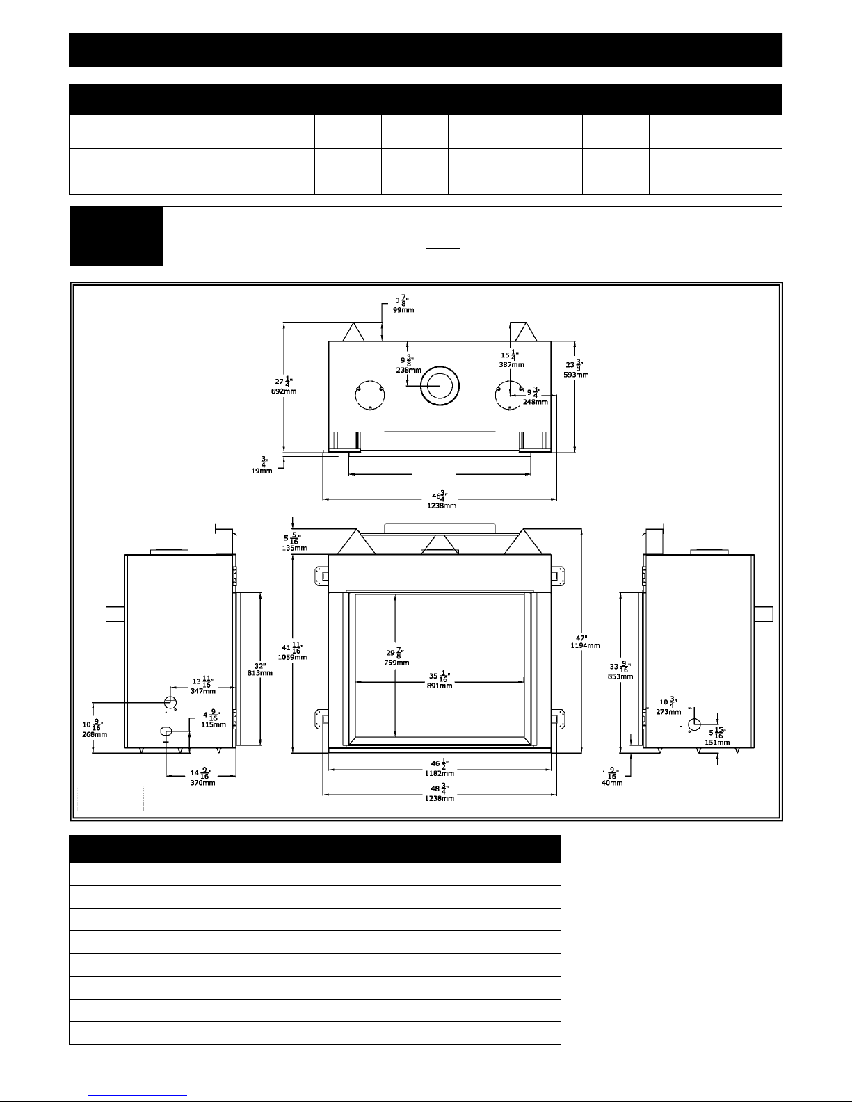
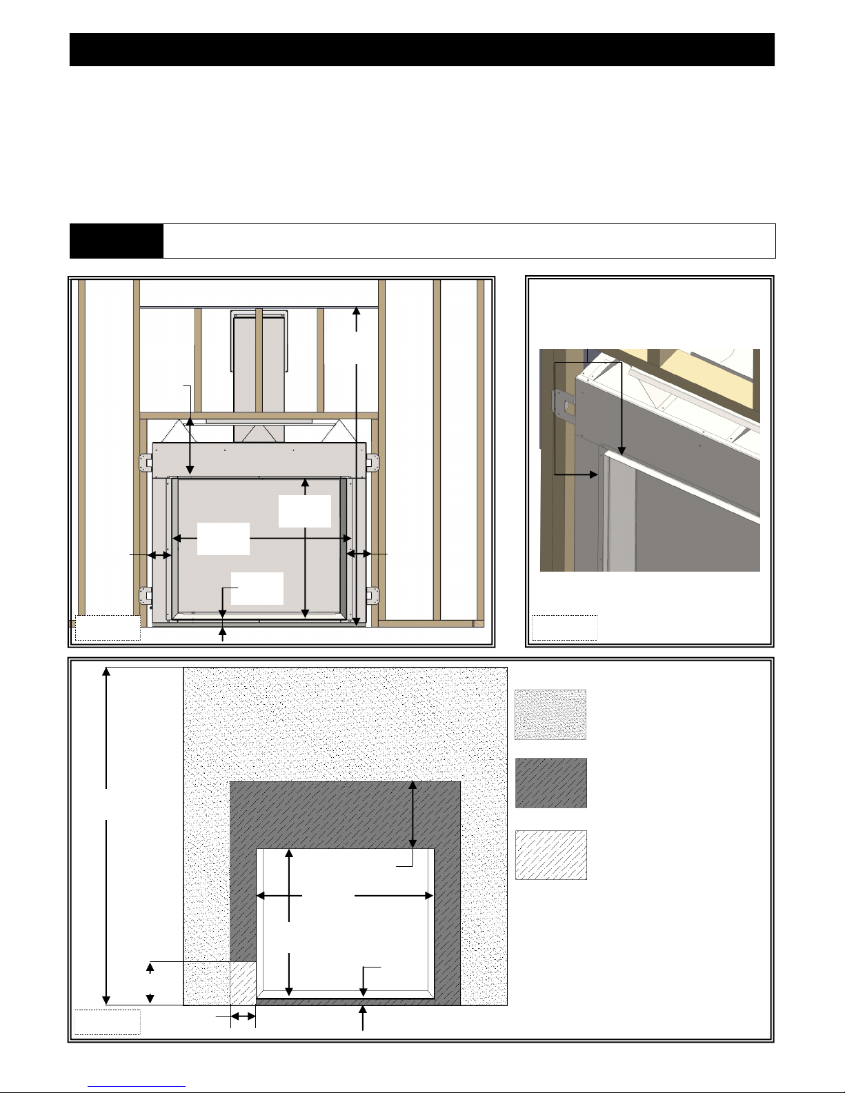
FIREPLACE
DIMENSIONS
WARNING
SPECIFICATIONS
FIREPLACE DIMENSIONS
DESCRIPTION Height Width Back Width Depth Opening
INCHES
MILLIMETERS
All stand -off brac kets must be attached to firepl ace. Do not remove. Top stand -o ff brac kets are not load bear ing.
Non-combustible zone: Top stand-offs provide 5-5/16” (135mm) minimum clearance to header. Use only non -combustible
material in this area for entire width of fireplace. Do not use wood, sheetrock etc. in this zone. Other clearances apply.
All clearances must be maintained.
41-11/16 46-1/2 41-11/16 23-3/8 38-3/8 32 5-5/16 9-3/8
1059 1182 1059 593 975 813 135 238
TOP
Width
Glass Frame
Height
Top Stand-off
Height
Back to vent
center
38 ⅜”
(975mm)
LEFT SIDE RIGHT SIDE
Figure 5a
CLEARANCES
FRONT
Top of unit face to framing 5-5/16” (135mm)
From unit left & right side stand-offs 0”
From unit back stand-offs 0”
From bottom stand-offs 0”
Top of unit face to ceiling 30-5/16” (770mm)
Side of finishing edge to adjacent sidewall 6” (152mm)
Unit front to combustibles 36” (914mm)
Mantel 9” (229mm) deep from floor fireplace is sitting on 47” (1194mm)
5

SPECIFICATIONS
ADDITIONAL COMPONENTS REQUIRED
Vent System: Approved venting listed on page 17 of this installation manual.
INSTALLATION OVERVIEW
NOTE The qualified installer should follow the procedure best suited for the installation.
1. Frame an opening for fireplace, allowing for vent installation and type of installation (corner or flat wall application).
2. If masonry (optional) is used, prepare foundation for the masonry load. A lintel is required to support the added weight above fireplace.
3. Attach stand-off brackets and nailing flanges to fireplace.
4. Insert fireplace into framing.
5. Install hearth (if applicable).
6. Complete gas line installation.
7. Complete electrical hook-up. Install any standard or optional electrical components at this time.
8. Complete venting installation.
9. Secure fireplace to framing with nailing flanges. Verify all clearances at this point.
10. Install facing material, mantel or cabinetry.
11. Install burner media.
12. Install finishing material and any other optional accessories.
13. Verify proper operation of fireplace and all components.
6
SPECIFICATIONS
PLACEMENT CLEARANCE REQUIREMENTS
This fireplace must be installed on a level surface capable of supporting fireplace and venting.
Fireplace must be placed directly on wood or non-combustible surface (not linoleum or carpet) extending entire depth and width of
fireplace.
Due to high surface temperatures, fireplace should be located out of traffic and away from furniture and draperies.
This fireplace may be installed in a bedroom.
Please be aware of the large amount of heat this fireplace will produce when determining a location.
TELEVISION POSITIONING CONSIDERATIONS
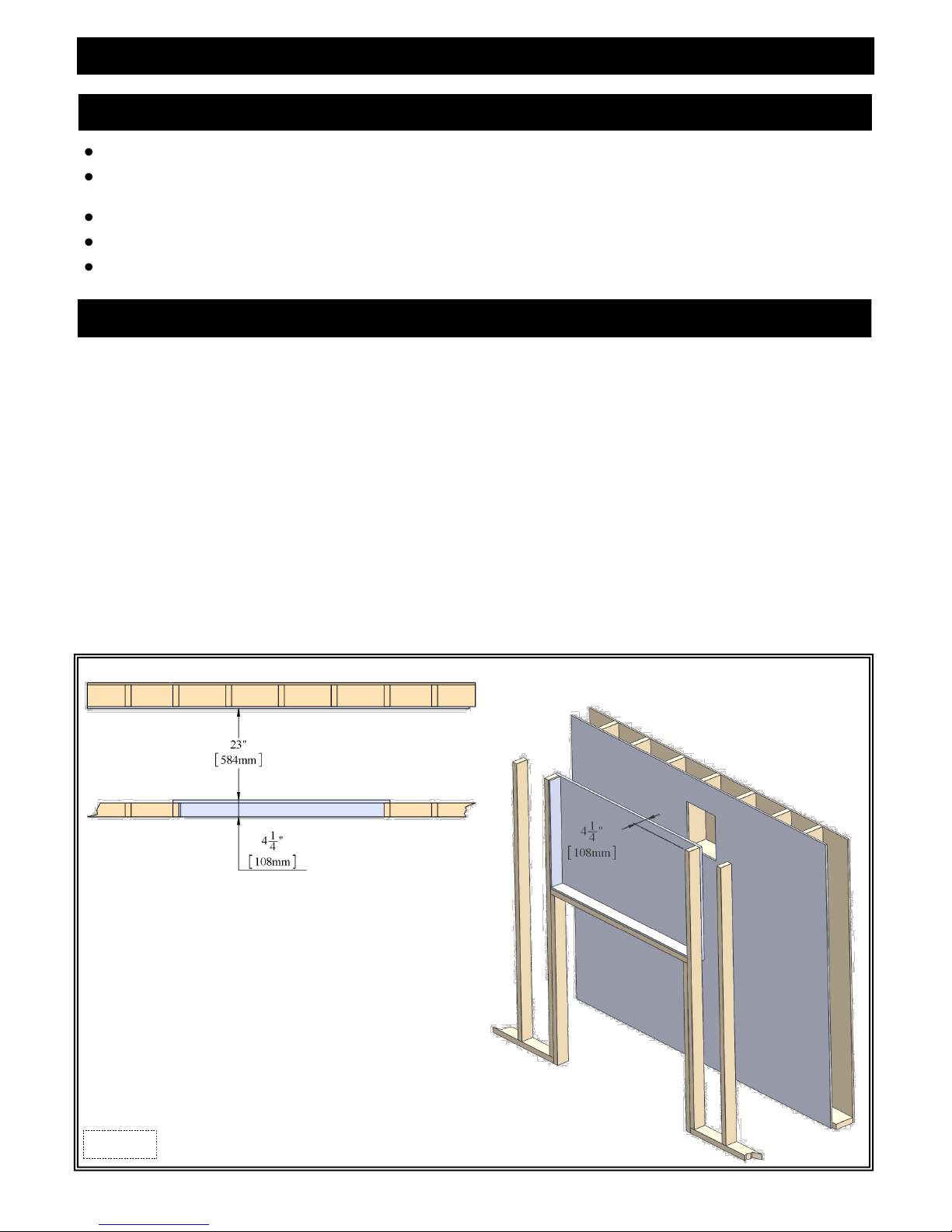
Mounting a TV above a fireplace has become common practice. With this in mind, we conducted tests to determine possible surface
temperatures reached above the fireplace.
Test results determined temperatures did not exceed 125° F (52°C) when the following criteria were met:
4-1/4” (108mm) deep internal chase constructed above the fireplace.
Mantel installed above fireplace at maximum depth of 9” (229mm) / minimum height from floor; 47” (1194mm).
Even though temperature tests were performed, mantel depths, ceiling heights, and other factors will affect temperatures, therefore
we advise you to read the following paragraphs carefully before considering installing a television above your fireplace.
Most TV manufacturers specify in their instructions that a TV should not be installed on, near, or above a heat source. Television location
rests solely on the homeowner. Hussong Manufacturing will not be held liable for any adverse effects on a TV located near a K ozy Heat
Fireplace that may be caused by heat.
TV operating temperature is also affected by wall and mantle construction material. It is the customers responsibility to sat isfy themselves
that their TV mounting and mantle design will not exceed the listed maximum operating temperature of their electronic goods.
Figure 7a
7
FIREPLACE PREPARATION
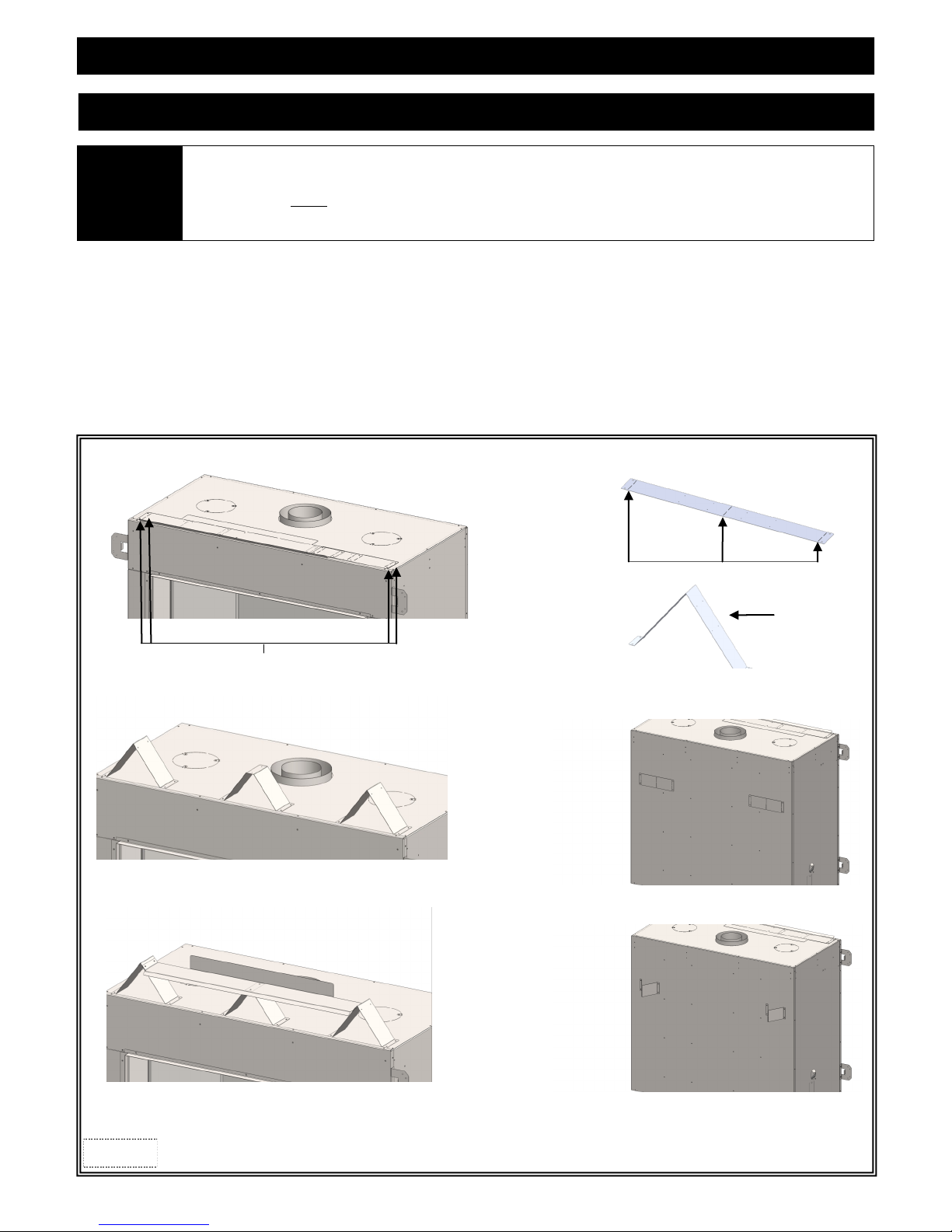
STAND-OFF / STAND-OFF HEAT SHIELD ASSEMBLY & INSTALLATION
Top and back stand-off brackets must be formed and attached prior to positioning fireplace into framed opening.
WARNING
Top stand-off brackets and the stand-off heat shield are attached to fireplace top, back stand-offs are attached to back of fireplace in a flat
state for shipping.
1. Remove and save (4) screws securing top stand-off heat shield and stand-off brackets. Form each stand-off bracket as shown.
2. Re-attach top stand-off brackets to fireplace using screws previously removed along with (8) screws provided in fireplace components
packet.
3. Form stand-off heat shield and attach to top stand-off brackets with (6) screws provided in fireplace components packet.
(Flange on stand-off heat shield faces up and to back of fireplace).
4. Remove, form and reattach back stand-off brackets using screws (4) previously removed and (4) provided in components packet.
Top stand-offs provide 5-5/16” (135mm) minimum clearance to header. Use only non-combustible material in this area for entire
width of fireplace. Do not use wood, sheetrock, etc. in this zone. Other clearances apply. All clearances must be maintained.
Top stand-off brackets are not load bearing.
TOP STAND-OFF BRACKETS AS SHIPPED
REMOVE SCREWS SECURING STAND-OFF BRACKETS
TOP STAND-OFF
BRACKETS INSTALLED
ALIGN HOLES IN FORMED TOP STAND-OFFS WITH HOLES IN
FIREPLACE TOP. SECURE WITH SCREWS (4 ea).
FORM STAND-OFF BY BENDING AT PERFORATIONS
FORMED STAND-OFF
BACK STAND-OFF BRACKETS AS SHIPPED
STAND-OFF HEAT
SHIELD INSTALLED
ALIGN HOLES IN FORMED STAND-OFF HEAT SHIELD WITH
HOLES IN STAND-OFF BRACKETS. SECURE WITH (6) SCREWS.
Figure 8a
BACK STAND-OFF BRACKETS INSTALLED
8
FIREPLACE PREPARATION
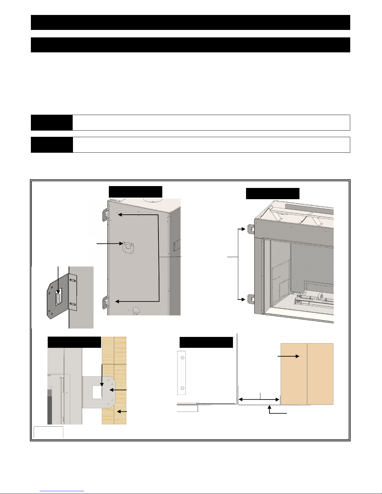
NAILING FLANGE ASSEMBLY & INSTALLATION
1. Remove (4) nailing flanges from fireplace sides.
2. With the 1/2” (13mm) long stand-offs on nailing flanges facing away from fireplace, align nailing flange with holes on outside corners
of fireplace. Secure with screws (provided in components packet) through slots in nailing flanges.
3. Bend perforation on nailing flange until parallel with fireplace face. Do not bend toward fireplace face.
4. Position framing stud against 1/2” (13mm) long stand-off (located on backside of nailing flange). Secure with nails or screws.
NOTE Depending on facing material, tabs can be adjusted forward or back wards up to 1/2” (13mm).
CAUTION Never permanently remove these assemblies from fireplace - they must be secured in place regardless of finish material used.
When installed, nailing flanges provide the minimum 1-1/8” (29mm) clearance from fireplace sides.
AS SHIPPED
1/2” (13mm) LONG
STAND-OFF FLANGE
FRONT VIEW
BACK VIEW
1/2” (13mm) LONG
STAND-OFF FLANGE
FRONT VIEW
NAILING FLANGES
INSTALLED
TOP VIEW
FRAMING STUD
Figure 9a
NAILING FLANGE
FRAMING STUD
1-1/8” (29mm)
CLEARANCE
NAILING FLANGE
9

FRAMING
WALL ENCLOSURE ROUGH OPENING
Determine whether wall surface will be flush with fireplace face (wall and fireplace face will be covered with non-combustible
material such as tile) or, framing will be flush with fireplace face, which results in a flat wall appearance.
IMPORTANT
MINIMUM FINISHED OPENING DIMENSIONS
(APPLIES TO BOTH HORIZONTAL AND VERTICAL VENTING TERMINATIONS)
47” (1194mm) High x 48-3/4” (1238mm) Wide x 27-1/4” (692mm) Deep.*
*27-1/4” (692mm) represents minimum distance from front of fireplace to back wall of framing. This is the minimum wall depth required
for wall surface material to cover fireplace front.
If you desire wall surface to be flush with fireplace face, subtract 1/2” (standard drywall depth) from this dimension.
If using another material, adjust accordingly.
Maintain all clearances to combustibles as outlined in this manual.
Framing dimensions should allow for wall covering thickness and fireplace facing materials. If using a hearth, adjust rough
opening size as necessary to maintain clearance requirements.
If installing optional #970 Heat Duct Kit, refer to instructions in Supplemental Installation and Homeowner Information manual.
WARNING
P RO VI DE A D E Q U A T E C L E A R A N C E S A R O U N D A I R O P EN I NG S I N T O T H E C O M B U S T I O N C H A M BE R.
Figure 10a
*
10
FRAMING
Determine exact position of your fireplace, including hearth height, width, and depth, (if applicable). If possible, place fireplace in such a
manner that vent termination will be placed between two studs, eliminating the need for additional framing.
If masonry is to be used (optional), prepare necessary foundation for the masonry load. When masonry construction is being used, a lintel
must be used over top of fireplace to support the added weight.
Build hearth to desired size and height. If a hearth extension is desired, combustible material may be used.
NOTE
WARNING
WARNING
FIRE
HAZARD
IMPORTANT
WARNING DO NOT RECESS VENT CAP INTO WALL OR SIDING.
Consider height of hearth finish material (stone, brick, etc.) when building fireplace platform. The bottom finishing edge of
fireplace must be level with finished hearth extension to allow for proper fit of contemporary frames.
Install fireplace on hard metal or wood surface extending the full width and depth of fireplace.
Minimum platform size: 46-1/2” (1182mm) wide x 23-3/8” (593mm) deep.
ABOVE FLOOR LEVEL INSTALLATIONS: Solid continuous platform must be constructed below appliance.
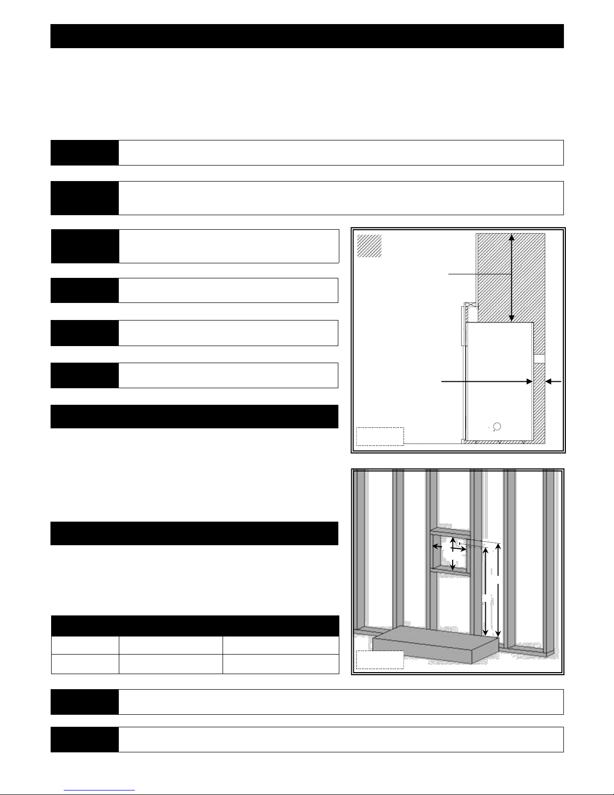
Non-combustible zone: No combustible materials allowed on
top of fireplace within shaded area for entire width and depth
of fireplace with the exception of the header. Figure 11a.
Do N O T inst a ll dir e c tly on c a r peti n g , viny l , or an y
c o m b u s t i b l e m a t e r i a l o t h e r t h a n w o o d .
Vent cap location must be in compliance with guidelines on
page 23 of this manual.
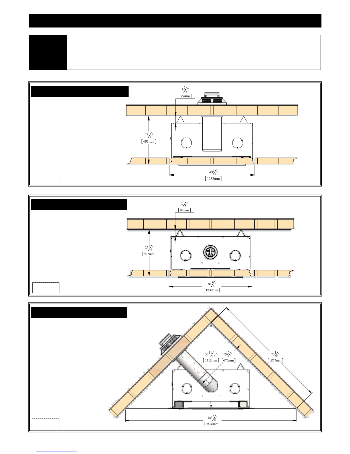
VERTICAL TERMINATIONS
Follow vent pipe man ufacturer’s installatio n instructions for vertical
termi n a t i ons. A min i m u m 1” (25 m m) c l e ar ance on al l s i d e s o f
vertical vent pipe must be maintained.
Non combustible zone
30-5/16” (770mm)
3-7/8” (99mm)
Figure 11a
HORIZONTAL TERMINATIONS
Frame a 12-1/2” (318mm) high (H) x 10-7/8” (276mm) wide (W) opening on
exterior wall for chimney termination. This opening size includes required
3” (76mm) top clearance and 1” (25mm) sides and bottom clearances for vent
systems.
MINIMUM HORIZONTAL FRAMING DIMENSIONS
VERTICAL RISE VENT PIPE TOP (A) FRAMED OPENING TOP (B)
18” (457mm) 68” (1.73m) 71” (1.8m)
CAUTION
CAUTION Due to high temperatures, this fireplace should be located out of traffic areas and away from furniture and draperies.
Cold air transfer area. The surrounding fireplace chase must comply with all clearances as outlined in this manual and be
constructed in compliance with local building codes. Outside walls should be insulated to prevent cold air from entering room.
W
H
B
A
Figure 11b
11
FACING AND FINISHING
This fireplace was designed to accommodate non-combustible facing material up to 1/2” (13mm) thick. Install non-combustible facing
material up to facing flange surrounding the glass frame assembly. Do not apply any material beyond this point. The glass frame assembly
must be removable.
Non-combustible material surrounding fireplace face is required. Illustrations below reflect minimum non-combustible material dimensions.
It is acceptable to pre-drill holes and use self-tapping screws to attach non-combustible material to fireplace face with the exception of the
lower left corner. See Figure 12c. Do not use excessively long screws.
WARNING Maintain minimum clearances to combustibles from fireplace and vent system.
5-3/8”
(137mm)
Figure 12a
72”
(1829mm)
13-3/8”
(339mm)
38 ⅜”
(975mm)
1-9/16”
(40mm)
32”
(813mm)
(975mm)
(1829mm)
38 3/8”
72”
14-1/2”
(362mm)
Facing flange
5-3/8”
(137mm)
Figure 12b
COMBUSTIBLE MATERIAL
ALLOWED
NON-COMBUSTIBLE MATERIAL
ONLY
NON-COMBUSTIBLE MATERIAL
ONLY
NO SCREWS ALLOWED
32”
(813mm)
9-7/16”
(240mm)
Figure 12c
5-3/8”
(137mm)
1-9/16”
(40mm)
12
TYPICAL INSTALLATION OPTIONS
Kozy Heat wall pass-thru (#800-WPT or #800-WPT2) must be used on all horizontal vent runs.
IMPORTANT
HORIZONTAL INSTALLATION
Figure 13a
The horizontal heat shield included with this fireplace must be installed when incorporating minimum horizontal venting.
This applies to Nat. and LP minimum horizontal venting configurations.
Horizontal vent heat shield not shown in illustrations below for clarity purposes only.
VERTICAL INSTALLATION
Figure 13b
CORNER INSTALLATION
Figure 13c
13
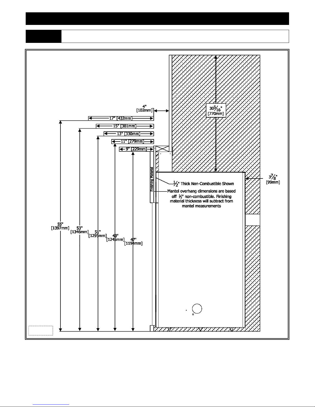
MANTEL REQUIREMENTS
WARNING
Non-combustible zone: No combustible materials allowed on top of fireplace within shaded area for entire width and depth
of fireplace with the exception of the header.
Figure 14a
14
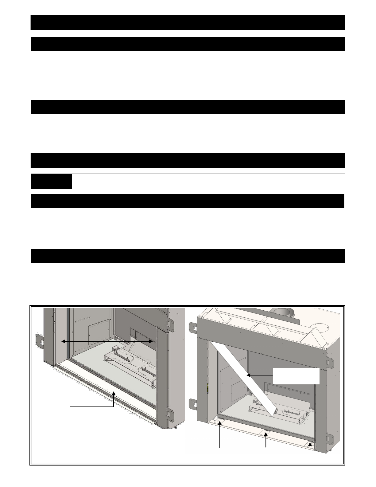
HEARTH PLATE / COMPONENT ACCESS DOORS
INSTALL HEARTH PLATE / COMPONENT ACCESS DOORS
1. Install glass frame assembly.
2. Install component access doors by rotating bottoms toward center of fireplace far enough to insert mounting studs at top of glass
valance through hole at top of access door. Lower bottom into position.
3. Install hearth plate, making sure long angled flange sits behind access door handles, securing in place.
REMOVE HEARTH PLATE / COMPONENT ACCESS DOORS
1. Remove hearth plate from front of fireplace by lifting up and out.
2. Remove component access doors by rotating bottoms toward center of fireplace until top of doors can be released from mounting stud
at top of glass valance.
GLASS FRAME
WARNING
DO NOT OPERATE THIS FIREPLACE WITH THE GLASS FRONT REMOVED, CRACKED OR BROKEN.
REPLACEMENT OF THE GLASS SHOULD BE DONE BY A LICENSED OR QUALIFIED SERVICE PERSON.
REMOVE GLASS FRAME ASSEMBLY
1. Remove hearth plate and component access doors.
2. Using a 7/16” nut driver, remove (3) nuts securing bottom of glass frame assembly.
3. Lift glass frame assembly up and off (3) tabs at top of firebox.
INSTALL GLASS FRAME ASSEMBLY
1. Place glass frame assembly top over tabs at top of firebox.
2. Reinstall (3) nuts to assembly bottom.
3. Reinstall component access doors and hearth plate.
Component Access Doors
Hearth Plate
Figure 15a
Rotate toward center
to remove and install
Nuts securing glass valance bottom
15
GAS LINE CONNECTION
GAS CONVERSION
This fireplace is manufactured for use with Natural Gas. Follow instructions included with conversion kit if converting to LP gas.
ATTENTION
CAUTION
NOTE
IMPORTANT
The conversion shall be carried out in accordance with the requirements of the provincial authorities having jurisdiction and in
accordance with the requirements of the ANSI Z223.1 installation code.
Installation of the gas line must only be done by a qualified person in accordance with local building codes, if any.
If not, follow ANSI 223.1.
Commonwealth of Massachusetts: Installation must be done by a licensed plumber of gas fitter.
A listed (and Commonwealth of Massachusetts approved) 1/2” (13mm) T-handle manual shut-off valve and flexible gas
connector (included) are connected to the 1/2” (13mm) control valve inlet. If substituting for these components, please consult
local codes for compliance.
This fireplace is equipped with a 3/8”(10mm) x 18” (457mm) long flexible gas connector and manual shut -off valve. The gas
line should be run to the point of connection where the shut-off valve and flexible gas line will connect.
The appliance and its appliance main gas valve must be disconnected from the gas supply piping system during any pressure
testing of that system at test pressures in excess of 1/2 psi (3.5 kPa). The appliance must be isolated from the gas supply p iping
system by closing its equipment shutoff valve during any pressure testing of the gas supply piping system at test pressures e qual
to or less that 1/2 psi (3.5 kPa).
For high altitude installations, consult the local gas distributor or the authority having jurisdiction for proper rating met hods.
The efficiency rating of this appliance is a product of thermal efficiency rating determined under continuous operating
conditions and was determined independently of any installed system.
NATURAL GAS LP GAS
MINIMUM INLET GAS PRESSURE 5” WC (1.25 kPa) (7” WC (1.74 kPa) recommended) 11” WC (2.74 kPa) (recommended)
MAXIMUM INLET GAS PRESSURE 10.5” WC (2.62 kPa) 13” WC (3.24 kPa)
HIGH ALTITUDE INSTALLATIONS
In the USA: The appliance may be installed at higher altitudes. Please refer to your American Gas Association
guidelines which state: the sea level rated input of Gas Designed Appliances installed at elevations above 2000ft. (610m)
ATTENTION
is to be reduced 4% for each 1000ft. (305m) above sea level. Refer also to National Fuel Gas Code, ANSI Z223.1/ NFPA
54 , local authori t i es, or code s wh i ch have jurisdi c t ion in your area r e gardin g the de -rate guidelin e s .
In Canada: When the appliance is installed at elevations above 4500ft. (1372m), the certified high altitude rating shall
be reduced at the rate of 4% for each additional 1000ft. (305m). Refer also to CSA-B149.1 Natural Gas and Propane
Installation Code, Local authorities, or codes which have jurisdiction in your area regarding the de-rate guidelines.
16
 Loading...