

kozy heat 961 DV Operating Manual
Model #961 DV
Installation & Operating
Instructions
WARNING: If the information in these
instructions are not followed exactly, a fire
or explosion may result causing property
damage, personal injury or loss of life.
Do not store or use gasoline or other flammable
vapors and liquids in the vicinity of this or any
other appliance.
WHAT TO DO IF YOU SMELL GAS:
‚ Do not try to light any appliance.
‚ Do not touch electrical switches; do not use
the phone in your building.
‚ Immediately call your gas supplier from a
neighbor’s phone. Follow the gas suppliers
instructions.
‚ If you cannot reach your gas supplier, call the
fire department.
‚ Installation and service must be performed by
a qualified installer, service agency or the gas
supplier.
This appliance may be installed in an aftermarket permanently located, manufactured home (USA
only) or mobile home, where not prohibited by local codes. This appliance is only for use with the
type(s) of gas indicated on the rating plate. This appliance is convertible for use with other gases.
An LP Gas conversion kit is included.
WARNING: Improper installation, adjustment, alteration, service or maintenance can cause injury, property damage, or
loss of life. Refer to this manual for assistance. For additional information, consult a qualified installer, service
agency or the gas supplier.
READ ALL INSTRUCTIONS CAREFULLY BEFORE INSTALLATION. FAILURE TO
INSTALL THIS FIREPLACE CORRECTLY CAN CAUSE SERIOUS STRUCTURAL AND FIRE
February 2008
IMPORTANT:
HAZARDS AND MAY VOID YOUR WARRANTY.

Index
DESCRIPTION PAGE
Safety Requirements ................................................................ 2-3
Specifications .......................................................................3
Minimum Clearances ..................................................................4
Determine Location ................................................................. 4-6
Rough-in Vent Systems Dimensions...................................... 5
Rough Opening Dimensions ........................................... 6
Glass Removal.......................................................................7
Venting Requirements .............................................................. 5-10
Horizontal / Vertical Requirements......................................5-7
Restrictor Installation................................................ 8
Horizontal Venting Instructions ........................................8-9
Vertical Venting Instructions / Restrictor Requirement........................ 10
Fan Installation .................................................................. 11-12
Minimum / Maximum Gas Supply Pressure / Run the Gas Line ................................. 13-14
Millivolt Board Removal / Installation ................................................... 14-16
Log Installation .....................................................................17
Wall Switch, Thermostat, Remote Control Installation ..........................................18
Complete the Installation ........................................................... 19-21
Attach Exterior Trim (Optional) / Securing the Fireplace ...................... 19
Install the 788-B Lintel .............................................. 19
Season Heat Dump Adjustment........................................ 20
Initial Start-up.................................................... 20
Re-install the Glass Assembly / Install the Grills .......................... 20-21
Lighting & Shutdown / Pressure Testing................................................. 22-24
Cleaning & Maintenance Requirements ....................................................25
Troubleshooting ................................................................. 26-27
Replacement Parts...................................................................28
Warranty Policy.................................................................. 29-30

COMMONWEALTH OF MASSACHUSETTS REQUIREMENTS
NOTE: The following requirements
reference various Massachusetts and
national codes not contained in this
manual.
For all sidewall horizontally vented gas fueled equipment installed in every dwelling, building or structure used in whole or
in part for residential purposes, including those owned or operated by the Commonwealth and where the side wall exhaust
vent termination is less than (7) feet above finished grade in the area of the venting , including but not limited to decks and
porches, the following requirements shall be satisfied:
INSTALLATION OF CARBON MONOXIDE DETECTORS
At the time of installation of the side wall horizontal vented gas fueled equipment, the installing plumber or gas-fitter shall
observe that a hard wired carbon monoxide detector with an alarm and battery back-up is installed on the floor level where
the gas equipment is to be installed. In addition, the installing plumber or gas-fitter shall observe that a battery operated or
hard wired carbon monoxide detector is installed on each additional level of the dwelling, building or structure served by
the side wall horizontal vented gas fueled equipment. It shall be the responsibility of the property owner to secure the services of qualified licensed professionals for the installation of hard wired carbon monoxide detectors.
In the event that the side wall horizontally vented gas fueled equipment is install in a crawl space or attic, the hard wired
carbon monoxide detector with alarm and battery back-up may be installed on the next adjacent floor level.
In the event that the requirements of this subdivision can not be met at the time of completion of installation, the owner
shall have a period of thirty (30) days to comply with the above requirements; provided, however, that during said thirty
(30) day period, a battery operated carbon monoxide detector with an alarm shall be installed.
APPROVED CARBON MONOXIDE DETECTORS
Each carbon monoxide detector as required in accordance with the above provisions shall comply with NFPA 720 and be
ANSI/UL 2034 listed and IAS certified.
SIGNAGE
A metal or plastic identification plate shall be permanently mounted to the exterior of the building at a minimum of eight (8)
feet above grade directly in line with the exhaust vent terminal for the horizontally vented gas fueled heating appliance or
equipment. The sign shall read, in print no less the one-half inch (1/2) in size, “GAS VENT DIRECTLY BELOW.
KEEP CLEAR OF ALL OBSTRUCTIONS”.
INSPECTION
The state or local gas inspector of the side wall horizontally vented gas fueled equipment shall not approve the installation
unless, upon inspection, the inspector observes carbon monoxide detectors and signage installed in accordance with the provisions of 248 CMR 5.08 (2) (a) 1 through 4.
EXEMPTIONS
The following equipment is exempt from 248 CMR 5.08 (2) (a) 1 through 4:
The equipment listed in Chapter 10 entitled “Equipment Not Required To Be Vented” in the most current edition
of NFPA 54 as adopted by the Board; and
Product Approved side wall horizontally vented gas fueled equipment installed in a room or structure separate
from the dwelling, building or structure used in whole or in part for residential purposes.

COMMONWEALTH OF MASSACHUSETTS REQUIREMENTS
MANUFACTURER REQUIREMENTS- GAS EQUIPMENT VENTING SYSTEM PROVIDED
When the manufacturer of Product Approved side wall horizontally vented gas equipment provides a venting system design or venting system components with the equipment, the instructions provided by the manufacturer for installation of
the equipment and the venting system shall include:
Detailed instructions for the installation of the venting system design or the venting system components; and
A complete parts list for the venting system design or venting system.
MANUFACTURER REQUIREMENTS- GAS EQUIPMENT VENTING SYSTEM NOT PROVIDED
When the manufacturer of Product Approved side wall horizontally vented gas equipment does not provide the parts for
venting the flue gases, but identifies “special venting systems”, the following requirements shall be satisfied by the manufacturer:
The referenced “special venting systems” instructions shall be included with the appliance or equipment
installation instructions and;
The “special venting systems” shall be Product Approved by the Board, and the instructions for that system shall
include a parts list and detailed installation instructions.
A copy of all installation instructions for all Product Approved side wall horizontally vented gas fueled equipment, all
venting instructions, all parts lists for venting instructions, and/or all venting design instructions shall remain with the appliance or equipment at the completion of the installation.
IMPORTANT:
READ
THIS MANUAL BEFORE INSTALLING AND USING THIS FIREPLACE
GAS FIREPLACE MODEL 961 DIRECT VENT
INSTALLATION
This appliance has been tested to & complies with ANSI Z21.88-2002·CSA 2.33-M02 ‘VENTED GAS FIREPLACE
HEATER’. Installation must conform with local building codes, or, in the a b sence of local building codes, with the
national fuel gas code, ANSI Z223.1- NFPA 54 (Current Edition). Approved for U.S. Installations only.
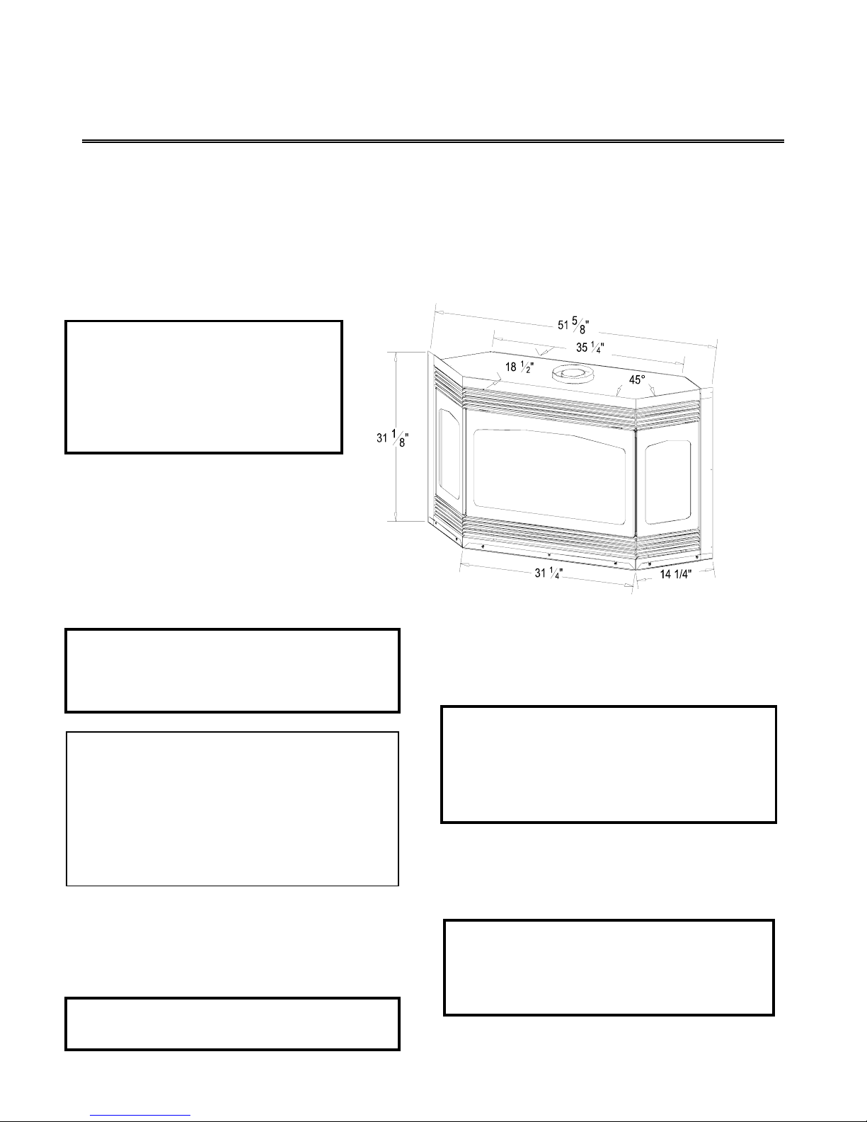
SPECIFICATIONS
Height: 31 1/8” Width: 51 5/8"
Back Width: 35 1/4" Depth: 18 1/2”
Flue Size: 4” exhaust
7” intake
Figure 1
INSTRUCTIONS
Do not use this fireplace if any part has been under
water. Immediately call a qualified service
technician to inspect this appliance and to replace
any part of the control system and any gas control
which has been under water.
COMMONWEALTH OF MASSACHUSETTS
INSTALLATIONS
WARNING: This Product Must Be Installed By A Licensed
Plumber Or Gas Fitter When Installed Within The
Commonwealth of Massachusetts.
IMPORTANT: Installation of a CO detector is required in
the fireplace room.
WARNING: DO NOT REPLACE THIS BURNER WITH
ANY OTHER SIZED BURNER. REPLACEMENT WITH
AN UNAUTHORIZED BURNER CAN RESULT IN
TEMPERATURES EXCEEDING THE LIMITS FOR THIS
FIREPLACE AND VOID YOUR WARRANTY.
DUE TO HIGH TEMPERATURES, THIS FIREPLACE
SHOULD BE LOCATED OUT OF TRAFFIC AND AWAY
FROM FURNITURE AND DRAPERIES.
YOUNG CHILDREN SHOULD BE CAREFULLY
SUPERVISED WHEN THEY ARE IN THE SAME ROOM
AS THIS FIREPLACE.
CHILDREN AND ADULTS SHOULD BE ALERTED TO
THE HAZARDS OF HIGH SURFACE TEMPERATURES
AND SHOULD STAY AWAY TO AVOID BURNS OR
CLOTHING IGNITION.
CLOTHING OR OTHER FLAMMABLE MATERIAL
SHOULD NOT BE PLACED ON OR NEAR THE
APPLIANCE.
MASONRY CONSTRUCTION: A lintel, PART #788B,
must be used to support the added weight when
masonry construction is used. See page #19 for
additional information.
IMPORTANT: DO NOT PLACE FACING MATERIAL
OVER THE EXTERIOR FACE. THE FACE WILL
EXPAND WHEN HEATED AND WILL CAUSE
CRACKING OF THESE MATERIALS. FAILURE TO
FOLLOW THESE INSTRUCTIONS WILL VOID YOUR
WARRANTY.
Page 1
Minimum clearance to combustibles:
Top Stand-off: 0" From flue vent:: 1"
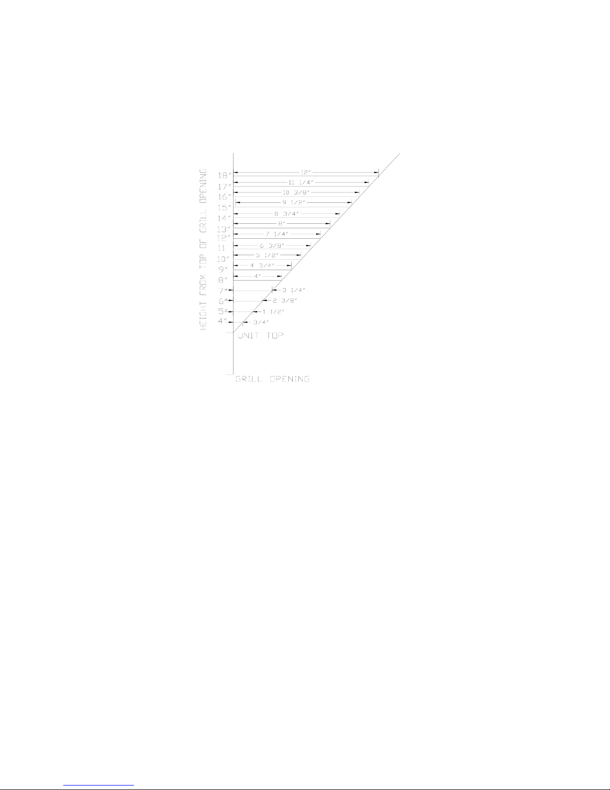
Sides & Back: 0” Heat Outlet grill to mantel: (See Figure 2)
Floor: 0" Bay Front to Adjacent Sidewall: 12”
Side Glass to Adjacent Sidewall: 3”
Mantel depth
Figure 2
A) DETERMINE LOCATION. Figure 3A.
Determine the exact position of your fireplace.
1.
2. This fireplace may be installed on either the outside
or inside of an exterior wall. See Figure 3A for
various installation options.
3. Horizontal Terminations: Determine the vent
run and termination cap location. If possible, place
the fireplace in such a manner that the piping will
be placed between two studs so additional framing
is not necessary.
4. The location of doors, windows, soffits/overhangs,
etc. must be considered in relation to where the
vent termination cap will be located.
5. Vertical Terminations: Follow instructions
included with the Simpson Dura-Vent DV-GS for
position of chimney. The #923-C adaptor must be
used.
6. All clearances to combustible requirements must be
maintained. Follow clearance requirements above.
7. If the optional heat ducts are used, their location
must be considered in relation to the fireplace.
The heat ducts may be vented into the same room as
the fireplace or may be vented to other ro oms. A
maximum run of 20 ft. is recommended.
Venting should be completed before framing in the
fireplace.
Refer to the instructions included with the #970 duct
kit for complete installation requirements.
8. If using the optional fan kit, 115V wiring should be
run to the lower left of the fireplace by a qualified
technician. A removable electrical box panel with
romex connector is located on the left side of the
fireplace. The wiring should be run prior to enclosing
the sides of the fireplace.
9. CAUTION - COLD AIR TRANSFER AREA. The
surrounding outside walls must be insulated to
prevent cold air from entering the room.
Page 2
NOTE: DUE TO HIGH TEMPERATURES, THIS FIREPLACE SHOULD BE LOCATED OUT OF TRAFFIC
AREAS AND AWAY FROM FURNITURE AND DRAPERIES.
Figure 3A
MODEL 961 DIRECT VENT
1
7
4
NOTE: Even though the minimum clearance from the back wall is 0", we recommend that you allow
an expansion space of 1/4" from the back wall to allow for heat expansion. If this room is not
left, the fireplace may make a loud "banging" noise when it heats up or cools down.
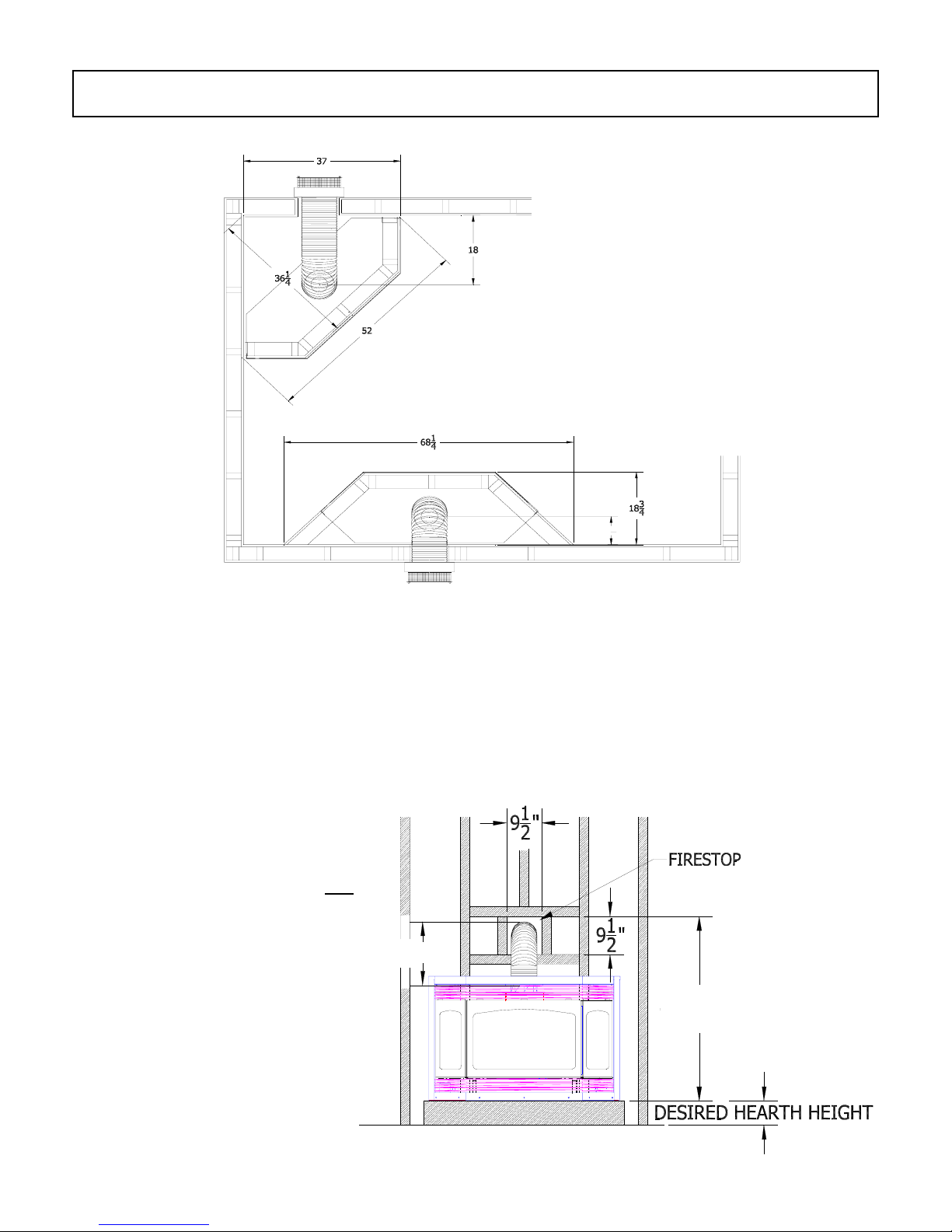
10. Cut an opening for the wall thimble, 9 ½” x 9 ½”. The top of this opening must be a minimum of 47 1/4"*
above the height of the hearth (optional) or floor the fireplace is setting on. See Figure 3B.
*Important: This measurement is
determined by the vertical height &
horizontal length of the venting application
TOP
desired. The measurement is to the
the pipe. Please refer to pages #5 - #10 of
this installation manual for requirements
& restrictions.
Figure 3B
of
17" MIN.
47 1/4" MIN.
Page 3
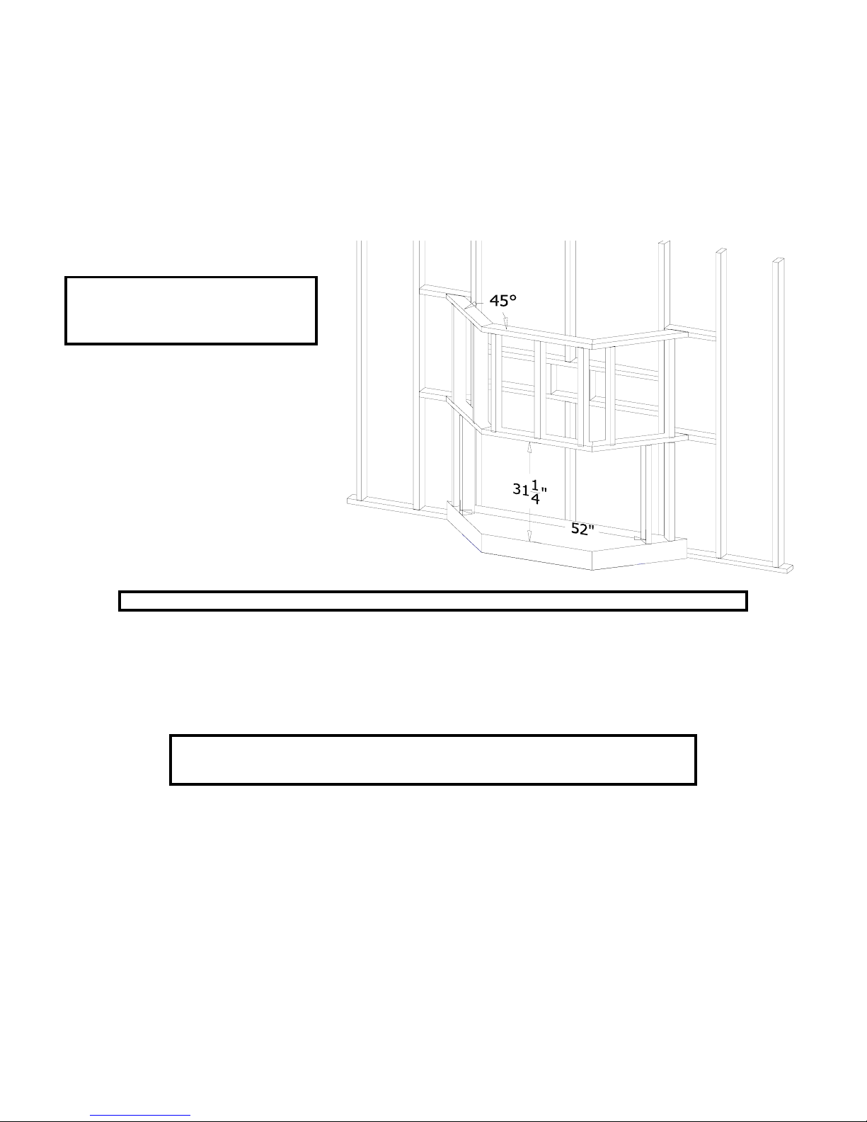
11. Rough in the wall enclosure (Figure 3C). Minimum rough opening dimensions are 52” w x 31 1/4" h. Depth is
determined by your specific application. Build the hearth, if used, to the desired size and height.
NOTE: A metal or wood panel extending the full width and depth of the fireplace (minimum size is 51 5/8” wide
x 18 ½" deep) must be placed under the fireplace when the fireplace is to be installed directly on carpet, tile or other
combustible materials other than wood flooring.
If masonry is to be used (optional), prepare the necessary foundation for the masonry load. When masonry
construction is being used, a lintel, part #788B, must be used over the top of the fireplace to support the added
weight.
NOTE: Provide for a minimum of 6" (152
mm) of clearance in front of the lower grill.
This will provide adequate space for opening
the lower grill to access control panel.
Figure 3C
NOTE: A hearth is not required. If a hearth is desired, combustible materials may be used.
Do not obstruct the upper and lower grill areas to allow proper ventilation air around the fireplace. Air enters the
fireplace through the lower grill, and exits out the upper grill. Do not block this passage.
12. Place the fireplace into position.
NOTE: DO NOT PLACE FACING MATERIAL OVER THE EXTERIOR FACE. THE FACE
WILL EXPAND WHEN HEATED AND WILL CAUSE CRACKING OF THESE MATERIALS.
FAILURE TO FOLLOW THESE INSTRUCTIONS WILL VOID YOUR WARRANTY.
Page 4

C) REMOVE GLASS ASSEMBLIES. See Figure 4.
Front Glass:
1. Locate the spring-loaded latch handles securing the center glass assembly.
2. Pull the handles out, then down to release the glass assembly.
3. Pull the bottom of the glass assembly out and lift up off the tabs (A) at the top.
4. Set aside where it will not be broken.
Side Glass:
1. Loosen and remove the (2) nuts securing each side glass assembly.
2. Pull the bottom of the glass assembly out and lift up off the tabs (at the top). Set aside.
3. Repeat steps #1 & #2 for remaining side glass assembly.
Figure 4
D) VENTING REQUIREMENTS
IMPORTANT: This fireplace is approved for use only with one of the following direct vent systems:
HORIZONTAL TERMINATIONS
#700 SERIES DIRECT VENT TERMINATION KITS: Used for horizontal terminations.
- Kozy Heat Direct Vent Kit #745 – for terminations of 4’ or less.
- Kozy Heat Direct Vent Kit #718 – for terminations of 8’ or less.
- Kozy Heat Direct Vent Extension Kit #746 – Used to extend the #745 kit
or #718 kit an additional 6’.
VERTICAL TERMINATIONS
SIMPSON DURA-VENT DV-GS DIRECT VENT CHIMNEY SYSTEM (4” X 6 5/8”)
- Simpson DV-GS chimney system – Used for vertical terminations.
- A restrictor is required & included with this fireplace.
- Adaptor #923-C is required to adapt the flue collars on the fireplace to the DV-GS
chimney system and is available from your dealer.
Page 5
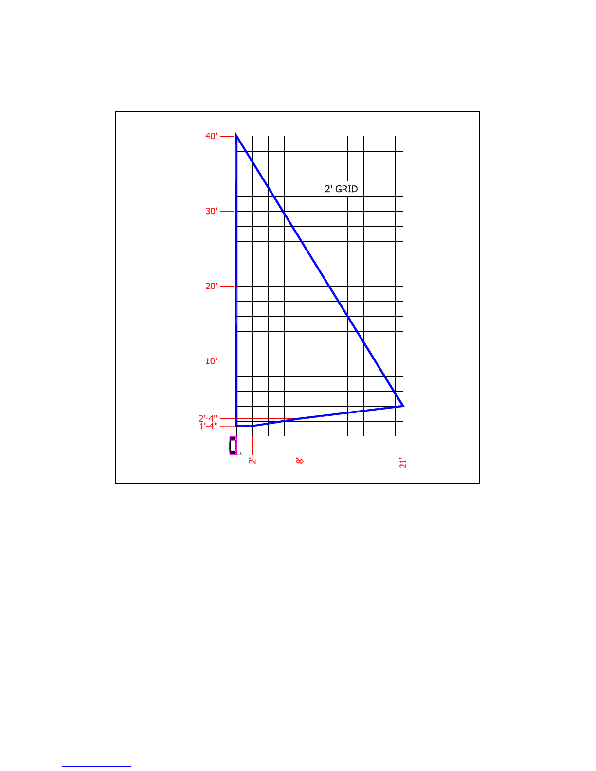
HORIZONTAL & VERTICAL VENTING CHART
VERTICAL RISE
1'-5"
HORIZONTAL RUN
EXAMPLE 1: Horizontal runs up to 2 ft. must have a minimum vertical rise of 17”.
EXAMPLE 2: If the horizontal run is 8 ft., the vertical rise required is 28”.
EXAMPLE 3: If the horizontal run is 21 ft., the vertical rise required is 48”.
IMPORTANT: All horizontal runs must maintain a ¼” rise per foot incline.
Page 6
TERMINATION VENT CAP LOCATION:
This gas appliance must not be connected to a chimney flue serving another type of appliance.
GENERAL:
1. Terminations against vinyl siding must use a vinyl siding protector. Follow instructions included.
2. DO NOT RECESS TERMINATION KIT INTO OUTSIDE BUILDING MATERIALS - i.e.: brick, stone, etc.. If nec essary,
extend framing so that termination kit will be exposed once building materials are installed.
3. Vent termination must not be located where it will become plugged by snow or other material. The flow of
combustion and ventilation air must be not obstructed.
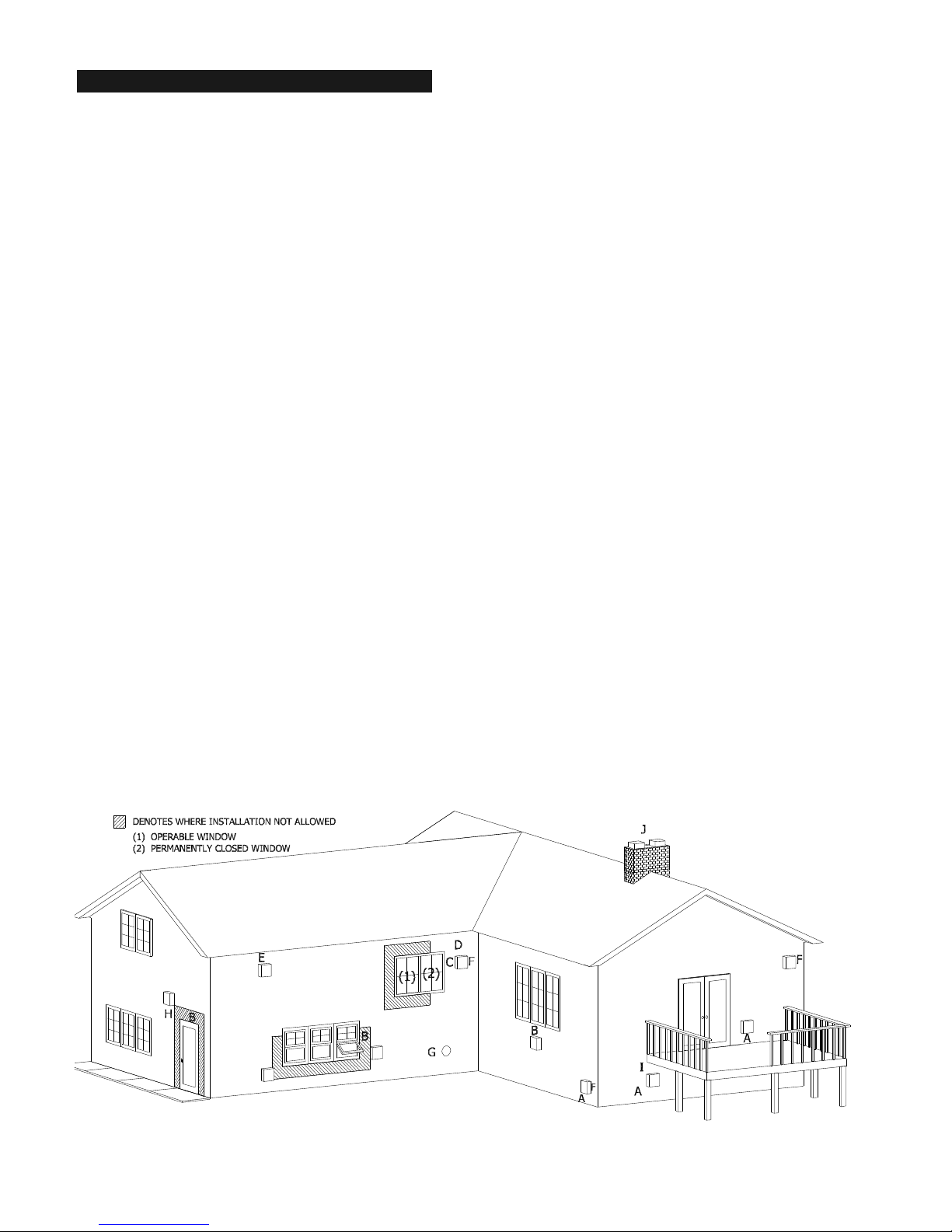
LOCATION CLEARANCES:
S Above grade, veranda, porch, deck, balcony - 12". (A)
S Operable window - 12". (B)
S Permanently closed window - 12" (recommended to prevent condensation on window (C)).
S Ventilated soffit - 24". (D)
S Unventilated soffit - 12". (E)
S Outside / inside corner - 12". (F)
S Meter / Regulator: Not to be installed above within 3 ft. horizontally from the center line of the regulator.
S Service regulator vent outlet - 3 ft. radius.
S Non-mechanical air supply inlet to building - 12".
S Combustion air inlet to any other appliance - 12".
S Mechanical air supply inlet - (G) CANADA: 6 ft. US: 3 ft. above if within 10 ft. horizontally.
S Note: MASSACHUSETTS INSTALLATIONS: 10 ft.
S Above furnace exhaust or inlet - 12".
S Above paved side-walk or paved driveway located on public property - 7 ft. * (H)
NOTE: A vent cannot be located directly above a sidewalk or paved driveway that is located between two
single family dwellings and serves both dwellings.
S Under veranda, porch, deck, or balcony (must be fully opened on a min. of 2 sides) - 12". (I)
S Between two horizontal terminations - 12".
S Between two vertical terminations - 12". (J) - Note: May be the same height.
* Clearance must be in accordance with local installation codes and the requirements of the gas supplier.
Figure 5
Page 7
 Loading...