

kozy heat 944 SEE-THRU, 944 PIER Operating Manual
INSTALLATION & OPERATING INSTRUCTIONS
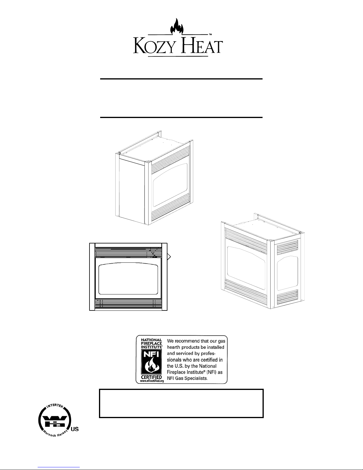
See-Thru Model
MODEL #944 DIRECT VENT
SEE-THRU / PIER GAS FIREPLACE
U.S. Patent Number: 5,931,154
Pier Model
U.S. Patent Number: 6,004,493
Front view
READ INSTRUCTIONS CAREFULLY BEFORE INSTALLATION. FAILURE TO
INSTALL THIS FIREPLACE CORRECTLY CAN CAUST SERIOUS STRUCTURAL
AND FIRE HAZARDS AND MAY VOID YOUR WARRANTY.
IMPORTANT:
www.kozyheat.com January 2007

INDEX
SAFETY REQUIREMENTS ..................................................... 1-2
SPECIFICATIONS ............................................................ 2-3
VENTING & CLEARANCE REQUIREMENTS ....................................... 3-4
PREPARE THE FIREPLACE...................................................... 5
POSITION THE FIREPLACE...................................................... 5
ROUGH-IN DIMENSIONS ...................................................... 6-7
VENTING REQUIREMENTS ................................................... 8-13
Horizontal / Vertical Requirements .................8-9
Restrictor Installation Instructions ................. 10
Horizontal Venting Instructions..................11-12
Vertical Venting Instructions ...................... 13
ROTATING THE CONTROL VALVE............................................... 14
FAN INSTALLATION........................................................ 15-16
MINIMUM / MAXIMUM GAS SUPPLY PRESSURE / RUN THE GAS LINE .............. 17-18
MILLIVOLT BOARD REMOVAL / INSTALLATION ................................ 18-19
LOG INSTALLATION .......................................................... 20
THERMOSTAT, WALL SWITCH, REMOTE CONTROL INSTALLATION .................. 21
PIER CONVERSION ........................................................ 22-23
COMPLETE THE INSTALLATION ............................................. 23-25
Seasonal Heat Dump Operation .................... 24
Replace the Glass Assemblies ..................... 25
Upper & Lower Grill Installation / Removal ........... 25
LIGHTING AND SHUTDOWN ................................................. 26-27
PRESSURE TESTING .......................................................... 28
MAINTENANCE REQUIREMENTS ................................................ 29
TROUBLE SHOOTING ...................................................... 30-31
REPLACEMENT PARTS........................................................ 32
WARRANTY POLICY ....................................................... 33-34
IMPORTANT:
READ THIS MANUAL BEFORE INSTALLING AND USING THIS FIREPLACE
KOZY HEAT MODEL #944 DIRECT VENT
See-Thru / Pier Fireplace
INSTALLATION INSTRUCTIONS
This appliance has been tested to and complies with ANSI Z21.88-2002CCSA 2.33-M02 ‘VENTED GAS FIREPLACE
HEATER’. Installation must conform with local building codes, or, in the absence of local building codes, with the
National Fuel Gas Code, ANSI Z223.1-NFPA 54 (Current Edition). Approved for U.S. Installations only.
This appliance may be installed in an after-market permanently located, manufactured (mobile) home, where not prohibited by local
codes.
This appliance is only for use with the type(s) of gas as indicated on the rating plate. This appliance is not convertible for use with
other gases, unless a certified kit is used. An LP Gas conversion is included with this fireplace.
WARNING: If the information in these instructions are not followed exactly, a fire or explosion may
result, causing property damage, personal injury or loss of life.
Do not store or use gasoline or other flammable vapors and liquids in the vicinity of this or any
other appliance.
WHAT TO DO IF YOU SMELL GAS:
‚ Do not try to light any appliance.
‚ Do not touch electrical switches; do not use the phone in your building.
‚ Immediately call your gas supplier from a neighbor’s phone. Follow the gas supplier’s
instruction.
‚ If you cannot reach your gas supplier, contact the fire department.
‚ Installation & service must be performed by a qualified installer, service agency or the gas
supplier.
WARNING: Do not use this appliance if any part has
COMMONWEALTH OF MASSACHUSETTS
INSTALLATIONS:
WARNING: This Product Must Be Installed By A Licensed
been under water. Immediately call a qualified
service technician to inspect the appliance and to
replace any part of the control system and any gas
control which has been under water.
Plumber Or Gas Fitter When Installed Within The
Commonwealth of Massachusetts.
NOTE: THIS FIREPLACE REQUIRES A DIRECT
IMPORTANT: Installation of a CO detector is required in
the fireplace room.
WARNING: Improper installation, adjustment,
alteration, service or maintenance can cause injury,
property damage, or loss of life. Refer to this manual
for assistance. For additional information, con sult a
qualified installer, service agency or the gas supplier.
VENT KIT FOR INSTALLATION. REFER TO
PAGE #3 FOR APPROVED SYSTEMS LISTING.
FOR VISUAL INSPECTION OF PROPER VENT
CONNECTION, UPON COMMPLETION OF
INSTALLING THE DIRECT VENT KIT, REMOVE
THE NUTS AND BAFFLE INSIDE THE UNIT TO
EXPOSE THE LOWER END OF THE FLUE GAS
EXIT.
Page 1
This fireplace is factory-shipped as a see-thru fireplace. A pier conversion kit is available from
your dealer.
IMPORTANT: DO NOT DIRECTLY ATTACH FACING MATERIAL ONTO THE EXT ERIOR FACES. THE FACES WILL
EXPAND WHEN HEATED AND WILL CAUSE CRACKING OF THESE MATERIALS. WARNING: ONLY NONCOMBUSTIBLE MATERIALS MAY BE USED OVER THE FACE. FAILURE TO FOLLOW THESE INSTRUCTIONS WILL
VOID YOUR WARRANTY.
WARNING: DO NOT REPLACE THIS BURNER UNIT WITH ANY OTHER SIZED BURNER. REPLACEMENT WITH AN
UNAUTHORIZED BURNER CAN RESULT IN TEMPERATURES EXCEEDING THE LIMITS FOR THIS UNIT, AND VOID
YOUR WARRANTY.
IMPORTANT NOTICE: DURING THE FIRST INITIAL BURNS, THIS UNIT WILL SMOKE AND GIVE OFF A PUNGENT
ODOR. THIS IS THE PAINT CURING AND IS NORMAL. WE RECOMMEND THAT YOU PROVIDE ADDITIONAL
VENTILATION DURING THIS CURING PROCESS.
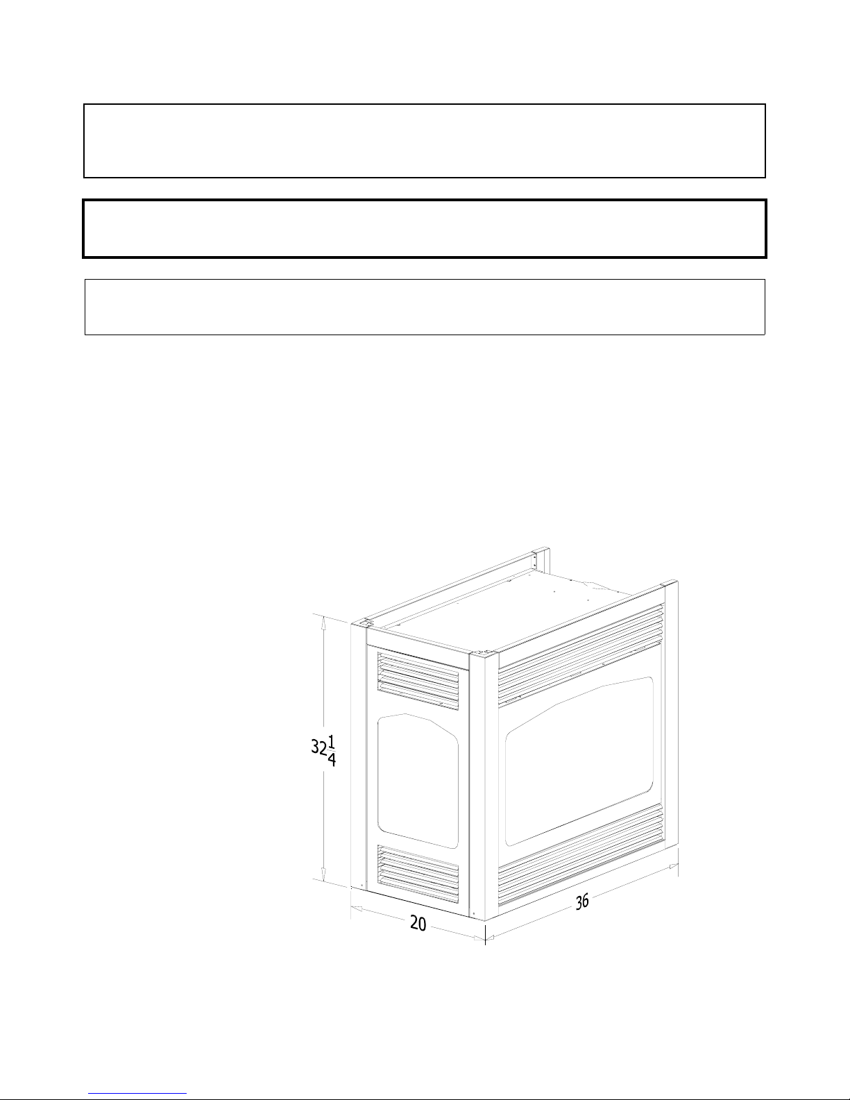
A) SPECIFICATIONS
Height: 32 1/4"
Width: 36"
Depth: 20"
Flue Size: 4" exhaust
7" intake
Figure 1A
Pier Model Shown
Page 2
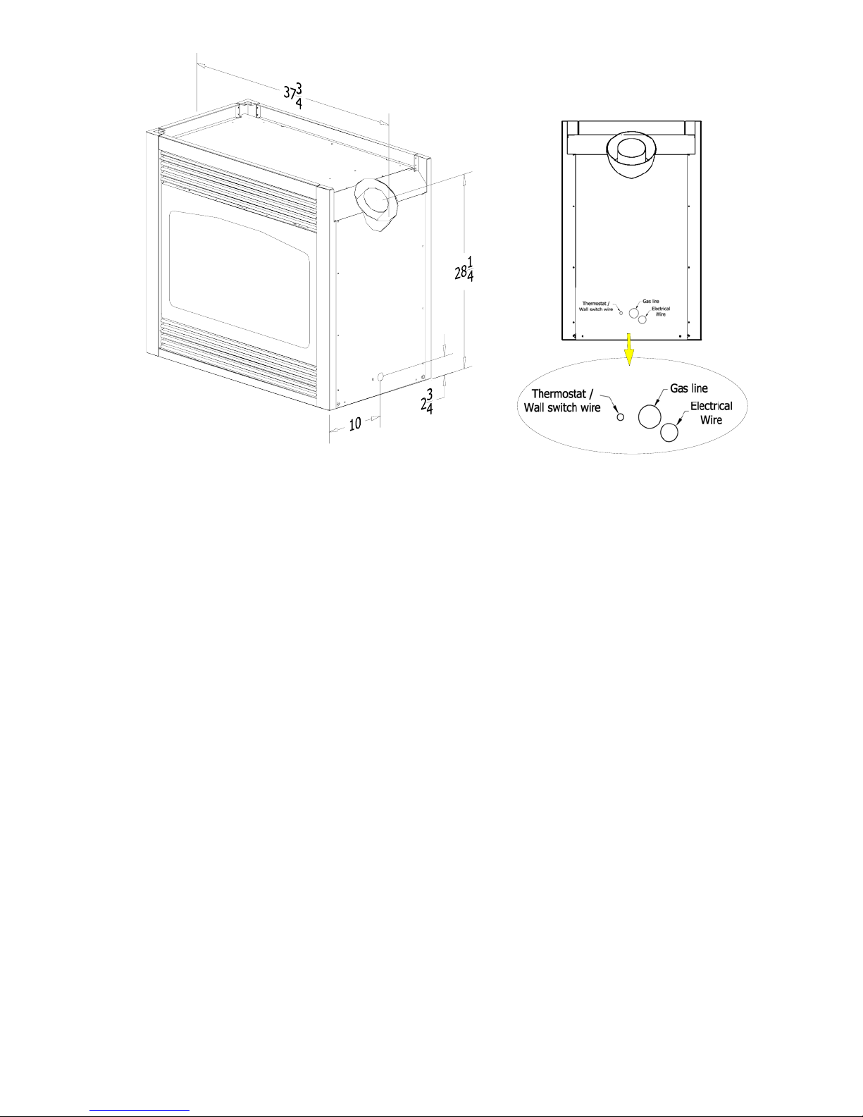
Figure 1B
MASONRY APPLICATIONS - The following lintel irons are available for masonry applications:
Pier installations: Part #788-C
See-thru installations: Part #617 - If masonry is used on both sides of a see-thru installation,
a #617 lintel iron is required for each side.
IMPORTANT: Lin
tels must be used to support the added weight when masonry construction
is used. Please contact your dealer
.
VENT SYSTEMS:
IMPORTANT: THIS FIREPLACE IS APPROVED FOR USE ONLY WITH ONE OF THE FOLLOWING DIRECT
VENT SYSTEMS:
KOZY HEAT #700 SERIES DIRECT VENT
CHIMNEY SYSTEM:
SIMPSON DURA-VENT DV-GS DIRECT VENT
CHIMNEY SYSTEM*: 4" X 6 5/8".
Horizontal terminations:
Horizontal or vertical terminations:
#745 DIRECT VENT TERMINATION KIT - for
terminations 4' or less.
*Adaptor #923-C is required to adapt the flue collars
to the Dura-Vent Chimney System.
#718 DIRECT VENT TERMINATION KIT -
for terminations greater than 4' but less than 8'.
Refer to pages #8-#12 for complete venting
installation instructions / requirements.
#746 DIRECT VENT EXTENSION KIT -
used in conjunction with #745 or #718.
The extension kit is expandable to 6'.
For visual inspection of proper vent connection, upon
completion of installing the direct vent kit, remove the
nuts and the baffle inside the unit to expose the
lower end of the flue gas exit.
Page 3
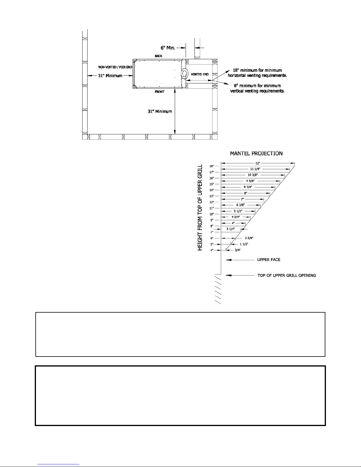
Figure 1C
Minimum Clearance to combustibles:
- Unit Top : 0"
- Front/Back: 31" from parallel wall
- Floor: 0"
- Flue Vent Top/Bottom: 2"
- Flue Vent Sides: 1 ½"
- Vented End*:
0" From unit side to framing
6" From unit side to adjacent side wall
- Non-Vented End: See-Thru Installations: 0"
Pier Installations: 31"
- Heat Outlet Grill to Mantel: (See Diagram A)
Diagram A
NOTE: The following clearances apply to both the Kozy Heat #700 Series flexible chimney system and the Simpson
Dura-Vent DV-GS chimney system for horizontal terminations.
Flue Vent Top: 2" Flue Vent Sides: 1 ½" Flue Vent Bottom: 2"
Vertical terminations using Simpson Dura-Vent DV-GS chimney system: 1" clearance
GAS CONVERSIONS:
This fireplace is manufactured for use with Natural Gas. An LP Gas conversion kit, part #OCK-H49L, is included with this fireplace.
Follow instructions included with the conversion kit.
Natural Gas Conversion Kit - #OCK-H30N: Used to convert an LP millivolt board to Natural gas.
LP Gas Conversion Kit - #OCK-H49L: Used to convert a Natural Gas millivolt board to LP gas.
The conversion shall be carried out in accordance with the requirements of the provincial authorities have jurisdiction and in
accordance with the requirements of the ANSI Z223.1 installation code.
Page 4
B) PREPARE THE FIREPLACE
Note: This fireplace is shipped as a standard see-thru model. When a pier model is desired, a pier conversion kit is used and
installed later in this manual.
Follow the instructions below for glass assemblies, regardless of which model you are installing:
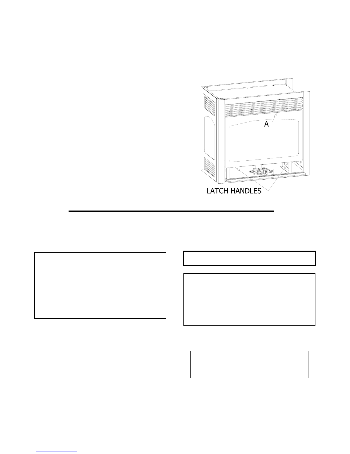
1. REMOVE THE GLASS ASSEMBLY:
Figure 2
Figure 2.
FIREPLACE ‘FRONT’ SIDE:
A. Locate the spring-loaded handles securing the glass
assembly (under the firebox).
B. Pull the handles out, then down to release the glass
assembly.
C. Pull the bottom of the glass assembly out and lift up off
the tabs at the top (A).
D. Set aside where it will not be broken.
FIREPLACE ‘BACK’ SIDE:
A. Locate the latches securing the glass assembly (under
the firebox).
B. Flip the back of the latch down to release the glass
assembly.
C. Pull the bottom the glass assembly out and lift up off the
tabs at the top (A).
D. Set aside where it will not be broken.
C) POSITION THE FIREPLACE. See Figures 3, 4A, 4B, & 4C.
1. Determine the exact position of your fireplace, vent run and vent
termination cap location.
NOTE: A hearth is not required. If a hearth is desired, combustible
materials may be used.
(Spring-loaded Handle side shown.)
HORIZONTAL TERMINATIONS
IMPORTANT: The vent termination cap location must comply with the
clearances as shown on page #9. A firestop adaptor is included with
this fireplace and must be used in conjunction with the chimney system
firestop / wall thimble to ensure proper clearances are maintained when
the chimney passes thru the wall.
VERTICAL TERMINATIONS
Refer to instructions included with the Simpson Dura-Vent DV-GS for
positioning the chimney system.
NOTE: Even though the minimum clearance from the top and sides is
0 ", we recommend that you allow an expansion space of 1/4" from the
top & sides to prevent cracking of face materials due to expansion of
the unit during heating. If expansion room is not left, the unit will make
a loud ‘banging’ noise when it heats up or cools down.
NOTE: When the unit is installed directly on carpeting, tile, or other
combustible materials other than wood flooring, it must be installed on
a metal or wood panel extending the full width and depth of the unit.
The minimum for the support platform under the unit is 20" deep by 36"
wide. If masonry is to be used (optional), prepare the nec essary
foundation for the masonry load. When masonry construction is being
used, a lintel must be used over the top of the unit to support the added
weight.
CAUTION: COLD AIR TRANSFER AREA. The surrounding outside
wall must be insulated to prevent cold air from entering the room.
Provide for a minimum of 6" of clearance in front of the lower grill. This
will provide adequate space to open and operate the controls behind
the lower grill.
Do not obstruct the upper and lower grill areas to allow proper
ventilation air around the fireplace. Room air enters the convection
passageway at the lower grill, and exits outt the upper grill. DO NOT
BLOCK THIS PASSAGE.
NOTE: Due to high temperatures, this unit should be located out
of traffic areas and away from furniture and draperies.
Rough opening dimensions differ on the ‘front and back sides’.
The opening on one side must be a minimum of 38" wide to
allow adequate room to slide the unit into position. See page #7.
NOTE: The control valve assembly may be rotated so that it is
accessible from the opposite side from which it was
manufactured. Refer to page
SEE-THRU INSTALLATIONS:
#14.
Page 5
HORIZONTAL TERMINATIONS:
1. Determine width & depth of the hearth (optional).
2. Determine the vent run and termination cap location. If possible, place the fireplace in such a manner that the piping will be placed
between two studs so additional framing is not necessary.
NOTE: Allow a minimum of 18" between the unit and inside wall to comply with minimum termination requirements. See
pages #8-#11 for horizontal termination guidelines.
3. Cut a hole for the wall thimble, 11 ½" high x 10 ½" wide. The top
of this hole must be a minimum:
#700 Series Flexible Vent System: 46" * above the height of the optional hearth.
Simpson Dura-Vent DV-GS System: 47 1/4" * above the height of the optional hearth.
* IMPORTANT: This measurement is determined by the vertical and horizontal length of the venting application desired. The measurement
is to the TOP of the pipe. Please refer to information below through page #12 of this installation manual for requirements and restrictions.
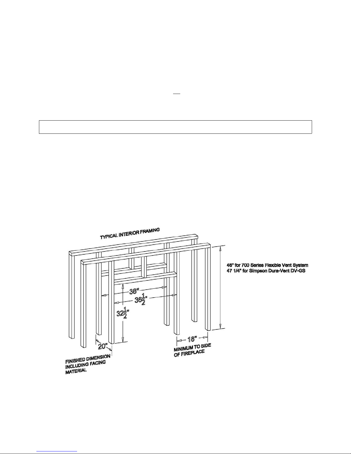
4. Rough in the wall enclosure.
SEE-THRU INSTALLATIONS: Rough opening dimensions are: Front face - 36 ½" wide x 32 ½" high Back face - 38" wide x 32 ½" high
(above the height of the optional hearth). Depth is determined by the thickness of face materials being used. IMPORTANT! The fireplace
depth is 20". See Figure 3 below.
Figure 3
SEE-THRU MODEL SHOWN IN ABOVE FIGURE
Page 6
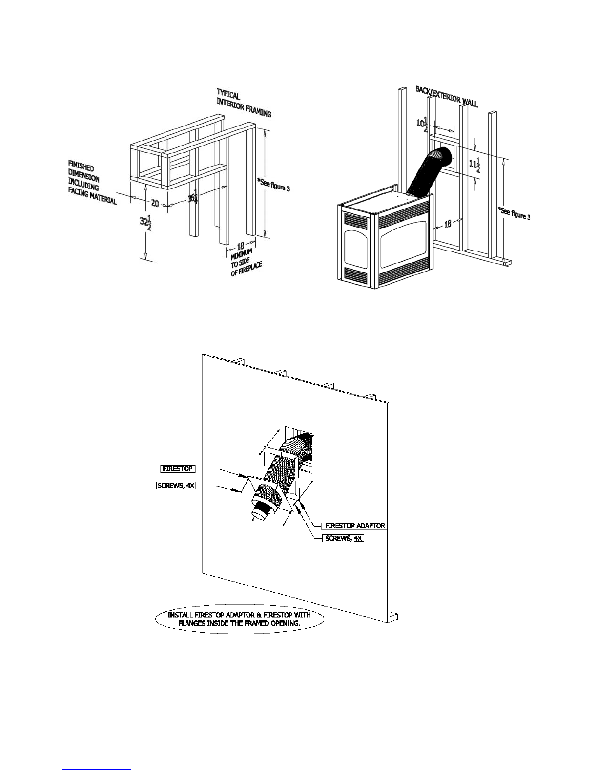
PIER INSTALLATIONS: Refer to Figures 4A & 4B. Rough opening dimensions are 36 1/4" wide x 32 1/2" high (above the height of
the optional hearth). Depth is determined by the thickness of facing materials being used. IMPORTANT! The fireplace depth is 20".
Figure 4A
Figure 4B
PIER MODEL SHOWN IN FIGURE ABOVE.
Figure 4C
Example of Typical Firestop Adaptor, (included with the fireplace), and Firestop (in clu ded with the #700 Series
flexible chimney system) installation on a finished wall.
Page 7
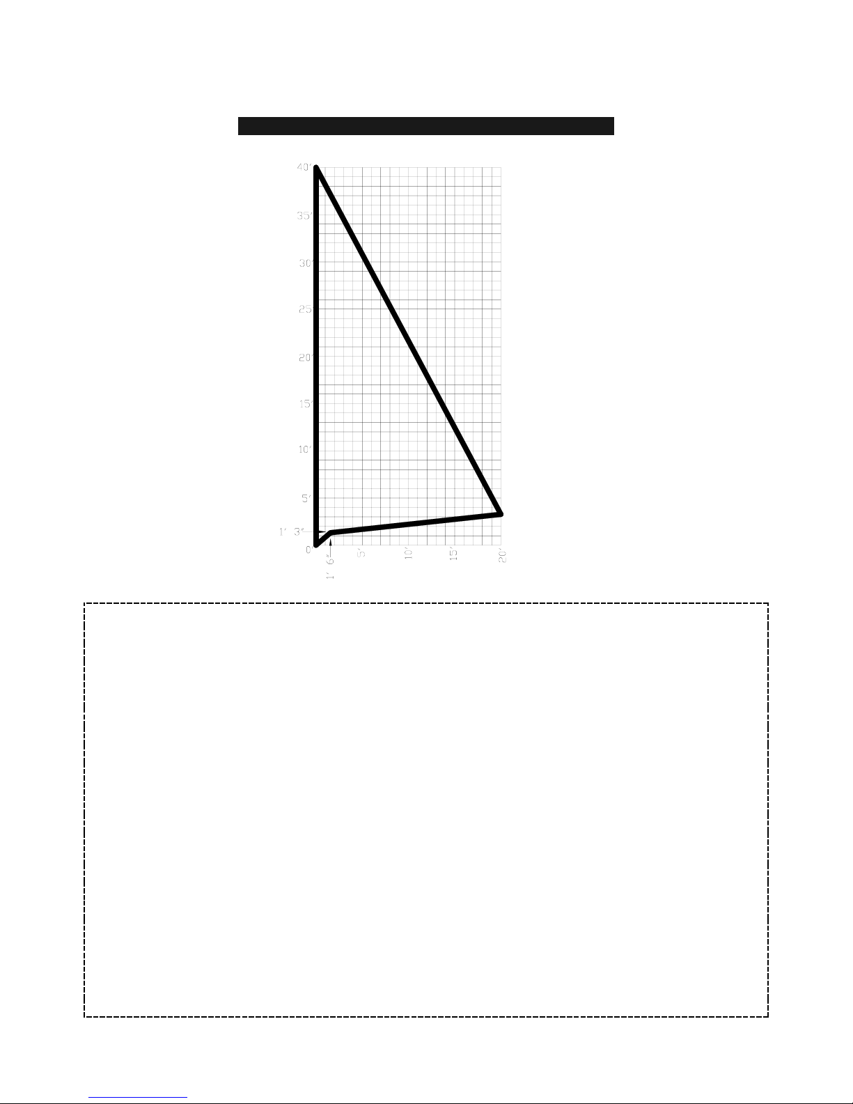
D) VENTING REQUIREMENTS
HORIZONTAL & VERTICAL VENTING CHART
HORIZONTAL TERMINATIONS: Minimum horizontal run: 15" (18" length of pipe)
(This is directly off the collars on the fireplace running at a 45-degree angle.)
Maximum horizontal run: 20 Ft.
Total run cannot exceed 20 Ft.
The first 15" of horizontal run must maintain a 45-degree angle. For each additional foot of horizontal run, a 1/4" rise per foot must
be maintained.
VERTICAL TERMINATIONS: Maximum vertical run: 40 Ft.
Vertically position the chimney by connecting (1) 45-degree elbow onto the #923-C
Dura-vent adaptor. C onnect the adaptor to th e stacks on the fireplace and seal
with the sealant provided
.
IMPORTANT: Each installation is different and some may require a restrictor plate. Contact the dealer
for more information.
Total horizontal and vertical run cannot exceed 40 Ft.
ELBOWS: 2 (90
o
) Included within maximum vent runs - For each additional 90o elbow, the maximum
horizontal run allowed must be decreased by 5-ft.
NOTE: (2) 45
o
= (1) 90
o
FOLLOW THE CHART ABOVE FOR COMBINATION VENT RUNS.
Page 8
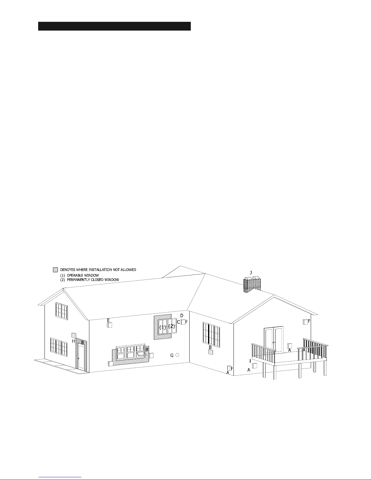
TERMINATION VENT CAP LOCATION:
This gas appliance must not be connected to a chimney flue serving another type of appliance.
GENERAL:
A) Terminations against vinyl siding must use a vinyl siding protector. Follow instructions included.
B) DO NOT RECESS TERMINATION K IT INTO OUTSIDE BUILDING MATERIALS - i.e.: brick, stone, etc.. If necessar y, ex ten d
framing so that termination kit will be exposed once building materials are installed.
C) Vent termination must not be located where i t will become plugged by snow or other material. The f low of combustion and ventilation
air must be not obstructed.
LOCATION CLEARANCES:
S Above grade, veranda, porch, deck, balcony - 12". (A)
S Operable window - 12". (B)
S Permanently closed window - 12" (recommended to prevent condensation on window. (C)
S Ventilated soffit - 24". (D)
S Unventilated soffit - 12". (E)
S Outside / inside corner - 12". (F)
S Meter / Regulator: not to be installed above within 3 ft. horizontally from the center line of the regulator.
S Service regulator vent outlet - 3 ft. radius
S Non-mechanical air supply inlet to building - 12".
S Combustion air inlet to any other appliance - 12".
S Mechanical air supply inlet - (G) CANADA: 6 ft. US: 3 ft. above if within 10 ft. horizontally.
S Above furnace exhaust or inlet - 12".
S Above paved side-walk or paved driveway located on public property - 7 ft. * (H)
NOTE: A vent cannot be located directly above a sidewal or paved driveway that is located between two single family dwellings
and services both dwellings.
S Under veranda, porch, deck, or balcony (must be fully opened on a min. of 2 sides) - 12". (I)
S Between two horizontal terminations - 12".
S Between two vertical terminations - 12". (J) - Note: May be the same height.
Note: MASSACHUSETTS INSTALLATIONS: 10 ft.
Figure 5
Page 9
 Loading...