

kozy heat 944 Installation And Operation Manual
Quality Fireplaces for Life
DIRECT VENT
SEE-THRU / PIER GAS FIREPLACE
WARNING: This product must be installed by
a licensed plumber or gas fitter when installed
in the Commonwealth of Massachusetts.
IMPORTANT: Installation of a CO detector is
required in the fireplace room when installed in
the Commonwealth of Massachusetts.
INSTALLATION
AND
OPERATION MANUAL
INSTALLER: LEAVE THIS MANUAL WITH THE APPLIANCE.
CONSUMER: RETAIN THIS MANUAL FOR FUTURE REFERENCE.
DO NOT
DISCARD
PIER MODEL SHOWN
WARNING: If the information in these instructions are not followed exactly, a fire or
explosion may result, causing property damage, personal injury or loss of life.
◙ Do not store or use gasoline or other flammable vapors and liquids in the vicinity of this or
any other appliance.
IF YOU SMELL GAS:
◙ Do not light any appliance.
◙ Do not touch any electrical switch: do not use any phone in your building.
◙ Immediately call gas supplier from a neighbors phone. Follow the gas supplier instructions.
◙ If you cannot reach your gas supplier, call the fire department.
◙ Installation and service must be performed by a qualified installer, service agency or the gas
supplier.
This appliance may be installed in an aftermarket permanently located, manufactured (mobile) home,
where not prohibited by local codes.
This appliance is only for use with the type (s) of gas indicated on
the rating plate. A conversion kit is supplied with the appliance.
Report No. 216-F-17-4
www.kozyheat.com
944 NOVEMBER2010-REV-08

INDEX
INTRODUCTION………………………………………………………………………………………….1
SAFETY REQUIREMENTS ..................................................................................................... 3-4
SPECIFICATIONS ...................................................................................................................... 5
VENTING & CLEARANCE REQUIREMENTS ............................................................................ 6
PREPARE THE FIREPLACE ..................................................................................................... 7
POSITION THE FIREPLACE ..................................................................................................... 7
ROUGH-IN DIMENSIONS ....................................................................................................... 8-9
VENTING REQUIREMENTS ............................................................................................... 10-14
Horizontal / Vertical Requirements ......................... 10-11
Restrictor Installation Instructions .............................. 12
Horizontal Venting Instructions .............................. 12-13
Vertical Venting Instructions ....................................... 14
ROTATING THE CONTROL VALVE ........................................................................................ 15
FAN INSTALLATION .......................................................................................................... 16-17
MINIMUM / MAXIMUM GAS SUPPLY PRESSURE / RUN THE GAS LINE ............................. 18
MILLIVOLT BOARD REMOVAL / INSTALLATION ................................................................. 19
LOG INSTALLATION ............................................................................................................... 20
THERMOSTAT, WALL SWITCH, REMOTE CONTROL INSTALLATION ............................... 21
PIER CONVERSION ........................................................................................................... 22-23
COMPLETE THE INSTALLATION ...................................................................................... 24-25
Seasonal Heat Dump Operation ..................................... 23
Replace the Glass Assemblies ....................................... 24
Upper & Lower Grill Installation / Removal .................... 24
LIGHTING AND SHUTDOWN ............................................................................................. 25-27
PRESSURE TESTING .............................................................................................................. 28
MAINTENANCE REQUIREMENTS .......................................................................................... 29
TROUBLE SHOOTING ....................................................................................................... 30-31
REPLACEMENT PARTS ......................................................................................................... 32
WARRANTY POLICY .......................................................................................................... 33-34
INTRODUCTION
Read this manual before installing or operating this appliance.
Please retain this owner’s manual for future reference.
CONGRATULATIONS!
We welcome you as a new owner of a Kozy Heat gas fireplace. Kozy Heat
products are designed with superior components and materials and assembled by
trained craftsmen who take pride in their work. The burner and valve assembly are
100% test-fired and the complete fireplace is thoroughly inspected before packaging
to ensure that you receive a quality product. Our commitment to quality and
customer satisfaction have remained the same for over 30 years. We offer a
complete line of gas and wood fireplaces, unique cabinets and stylish accessories to
compliment any décor. Adding a fireplace is one of the best ways to increase the
value of your home and we are proud to offer a network of dealers throughout the
country to help make your experience everything you imagine. We pride ourselves in
being dedicated to not only function and reliability, but customer safety as well.
We offer our continual support and guidance to help you achieve the maximum
benefit and enjoyment from your Kozy Heat gas fireplace.
Jim Hussong Dudley Hussong
President Board Chairman
Homeowner Reference Information
We recommend that you record the following information about your fireplace.
Model Name:______________________________ Date purchased/installed:____________
Serial Number:____________________________ Location on fireplace:_______________
Dealership purchased from:__________________ Dealer Phone:_____________________
Notes:_____________________________________________________________________
__________________________________________________________________________
__________________________________________________________________________
PAGE 2
SAFETY INFORMATION
This fireplace has been tested to and complies with ANSI Z21.88b-2008·CSA 2.33b-2008M02“VENTED GAS FIREPLACE HEATERS”
by OMNI-Test Laboratories, Portland, OR. Installation must conform with local building codes or in the absence of local building codes,
with the National Fuel Gas Code, ANSIZ223.1/NFPA 54 - Current Edition, or the Natural or Propane Installation Code, CSAB149.1
Installation and repair should be done only by a qualified service person. The appliance should be
inspected by a qualified service person before use. Annual inspection by a qualified service person is
required to maintain warranty. More frequent cleaning may be required due to excessive lint from
carpeting, bedding materials, etc. It is imperative that control compartments, burners and
circulation air passageways of the appliance be kept clean.
If this appliance is installed directly on carpeting, tile or other combustible material other than wood
flooring, the appliance shall be installed on a metal or wood panel extending the full width and depth
of the appliance.
Children and adults should be alerted to the hazards of high surface temperatures and should stay
away to avoid burns or clothing ignition.
Young children should be carefully supervised when they are in the same room as the appliance.
Clothing or other flammable material should not be place on or near the appliance.
Adequate accessibility clearances for servicing and proper operation must be maintained.
This appliance must not share or be connected to a chimney flue serving any other appliance.
Keep area around the appliance clear of combustible materials, gasoline and other flammable vapor
and liquids.
The flow of combustion and ventilation air must not be obstructed.
Due to high temperatures the appliance should be located out of traffic and away from furniture and
draperies.
The glass front or any part removed for servicing the appliance must be replaced prior to operating
the appliance. Work should be done by a qualified service technician.
Clean glass only when cool and only with non-abrasive cleansers.
Do not operate this appliance with the glass/frame assembly removed, cracked or broken. The glass
assembly, Part #700-07T, shall only be replaced as a complete unit, as supplied by Hussong Mfg. Co.,
Inc. Replacement of the glass assembly must only be performed by a licensed or qualified service person. DO NOT SUBSTITUTE MATERIALS.
Do not strike or slam glass assembly.
Any safety screen or guard removed for servicing the appliance must be replaced prior to operating
the appliance.
Under no circumstances should any solid fuel (wood, coal, paper or cardboard etc.) be used in this
appliance.
Keep burner and control compartment clean.
Do not use this fireplace if any part has been under water. Immediately call a qualified service
technician to inspect this appliance and to replace any part of the control system and any gas control
which has been under water.
PAGE 3

COMMONWEALTH OF MASSACHUSETTS REQUIREMENTS
NOTE: The following requirements reference
various Massachusetts and national codes not
contained in this manual.
For all sidewall horizontally vented gas fueled equipment installed in every dwelling, building or structure used in whole or in part for residential purposes,
including those owned or operated by the Commonwealth and where the side wall exhaust vent termination is less than (7) feet above finished grade in the
area of the venting, including but not limited to decks and porches, the following requirements shall be satisfied:
INSTALLATION OF CARBON MONOXIDE DETECTORS
At the time of installation of the side wall horizontally vented gas fueled equipment, the installing plumber or gas -fitter shall observe that a hard wired
carbon monoxide detector with an alarm and battery back-up is installed on the floor level where the gas equipment is to be installed. In addition, the installing plumber or gas-fitter shall observe that a battery operated or hard wired carbon monoxide detector is installed on each additional level of the dwelling, building or structure served by the side wall horizontal vented gas fueled equipment. It shall be the responsibility of the property owner to secure the
services of qualified licensed professionals for the installation of hard wired carbon monoxide detectors.
In the event that the side wall horizontally vented gas fueled equipment is installed in a crawl space or attic, the hard wired carbon monoxide detector with
alarm and battery back-up may be installed on the next adjacent floor level.
In the event that the requirements of this subdivision can not be met at the time of completion of installation, the owner shall have a period of thirty (30)
days to comply with the above requirements; provided, however, that during said thirty (30) day period, a battery operated carbon monoxide detector with
an alarm shall be installed.
APPROVED CARBON MONOXIDE DETECTORS
Each carbon monoxide detector as required in accordance with the above provisions shall comply with NFPA 720 and be ANSI/UL 2034 listed and IAS
certified.
SIGNAGE
A metal or plastic identification plate shall be permanently mounted to the exterior of the building at a minimum of eight (8) feet above grade directly in
line with the exhaust vent terminal for the horizontally vented gas fueled heating appliance or equipment. The sign shall read, in print no less the one-half
inch (1/2”) in size, “GAS VENT DIRECTLY BELOW. KEEP CLEAR OF ALL OBSTRUCTIONS”.
INSPECTION
The state or local gas inspector of the side wall horizontally vented gas fueled equipment shall not approve the installation unless, upon inspection, the
inspector observes carbon monoxide detectors and signage installed in accordance with the provisions of 248 CMR 5.08 (2) (a) 1 through 4.
EXEMPTIONS
The following equipment is exempt from 248 CMR 5.08 (2) (a) 1 through 4:The equipment listed in Chapter 10 entitled “Equipment Not Required To Be
Vented” in the most current edition of NFPA 54 as adopted by the Board; and Product Approved side wall horizontally vented gas fueled equipment in-
stalled in a room or structure separate from the dwelling, building or structure used in whole or in part for residential purposes.
MANUFACTURER REQUIREMENTS - GAS EQUIPMENT VENTING SYSTEM PROVIDED
When the manufacturer of Product Approved side wall horizontally vented gas equipment provides a venting system design or ven ting system components with the equipment, the instructions provided by the manufacturer for installation of the equipment and the venting system shall include:
Detailed instructions for the installation of the venting system design or the venting system components; and
A complete parts list for the venting system design or venting system.
MANUFACTURER REQUIREMENTS - GAS EQUIPMENT VENTING SYSTEM NOT PROVIDED
When the manufacturer of Product Approved side wall horizontally vented gas equipment does not provide the parts for venting the flue gases, but identifies “special venting systems”, the following requirements shall be satisfied by the manufacturer:
The referenced “special venting systems” instructions shall be included with the appliance or equipment installation instructions and;
The “special venting systems” shall be Product Approved by the Board, and the instructions for that system shall include a parts list and
detailed installation instructions.
A copy of all installation instructions for all Product Approved side wall horizontally vented gas fueled equipment, all venting instructions, all parts lists
for venting instructions, and/or all venting design instructions shall remain with the appliance or equipment at the completion of the installation.
PAGE 4
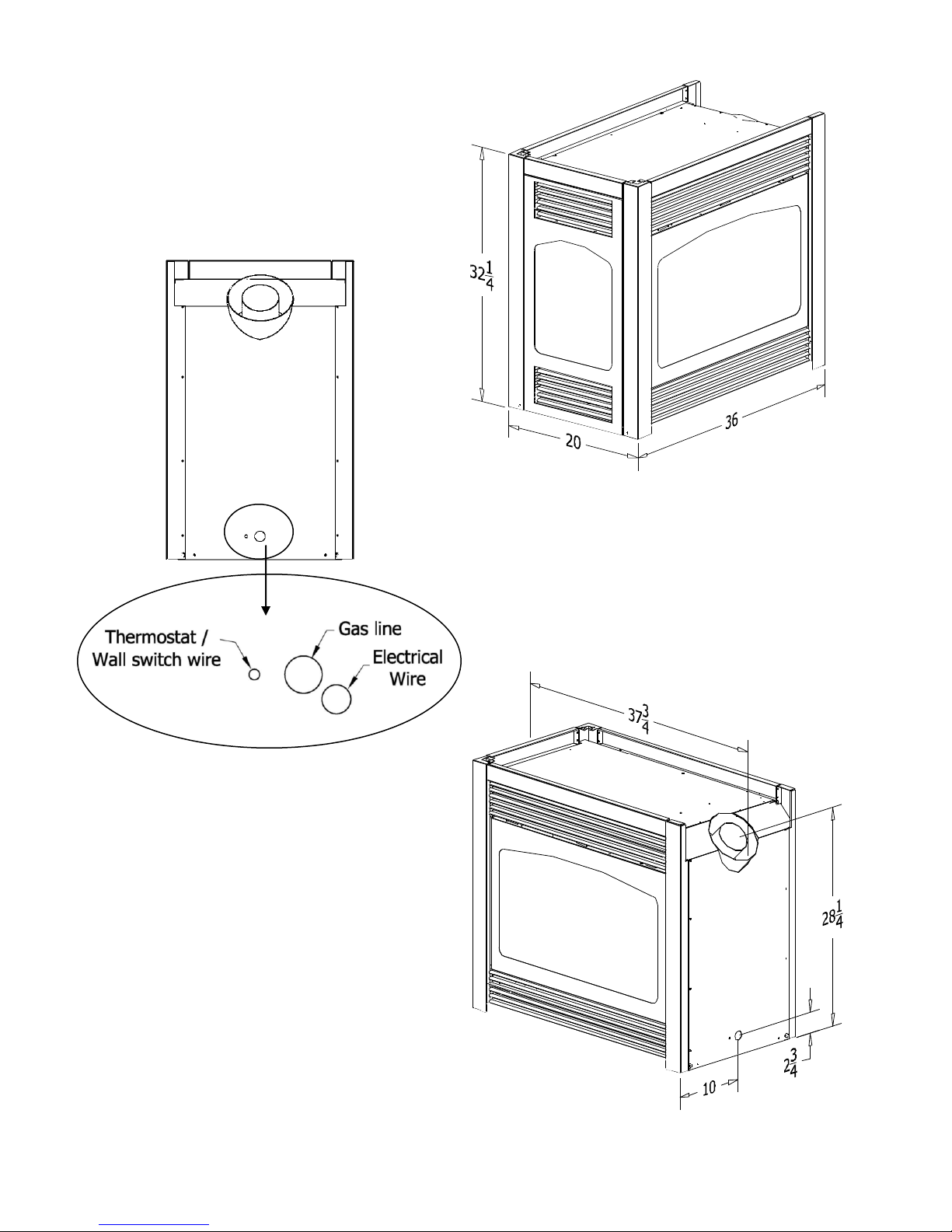
SPECIFICATIONS
Height: 32 1/4"
Width: 36"
Depth: 20"
Flue Size: 4" exhaust
7" intake
Figure 1A
Pier Model Shown
MASONRY APPLICATIONS -
The following lintel irons are available for masonry applications:
Pier installations: Part #788-C
See-thru installations: Part #617
If masonry is used on both sides of a see-thru installation, a
#617 lintel iron is required for each side.
IMPORTANT: Lintels must be used to support the added weight
when masonry construction is used. Please contact your dealer.
This fireplace is factory-shipped as a see-thru fireplace.
A pier conversion kit is available from your dealer.
Figure 1B
PAGE 5
VENT SYSTEMS:
IMPORTANT: THIS FIREPLACE IS APPROVED FOR USE ONLY WITH ONE OF THE FOLLOWING DIRECT VENT SYSTEMS:
KOZY HEAT #700 SERIES DIRECT VENT CHIMNEY SYSTEM: Horizontal terminations:
#745 DIRECT VENT TERMINATION KIT— for terminations 4' or less.
#718 DIRECT VENT TERMINATION KIT— for terminations greater than 4' but less than 8'.
#746 DIRECT VENT EXTENSION KIT - used in conjunction with #745 or #718. The extension kit is expandable to 6'.
RIGID PIPE DIRECT VENT CHIMNEY SYSTEMS*: 4" X 6 5/8". Horizontal or vertical terminations:
ICC, SELKIRK, AMERICAN METALS, SECURITY, SIMPSON DURA-VENT
*Adaptor #923-C is required to adapt the flue collars to the Dura-Vent Chimney System.
For visual inspection of proper vent connection, upon completion of installing the direct vent kit, remove the nuts and the baffle inside the
unit to expose the lower end of the flue gas exit.
Figure 1C
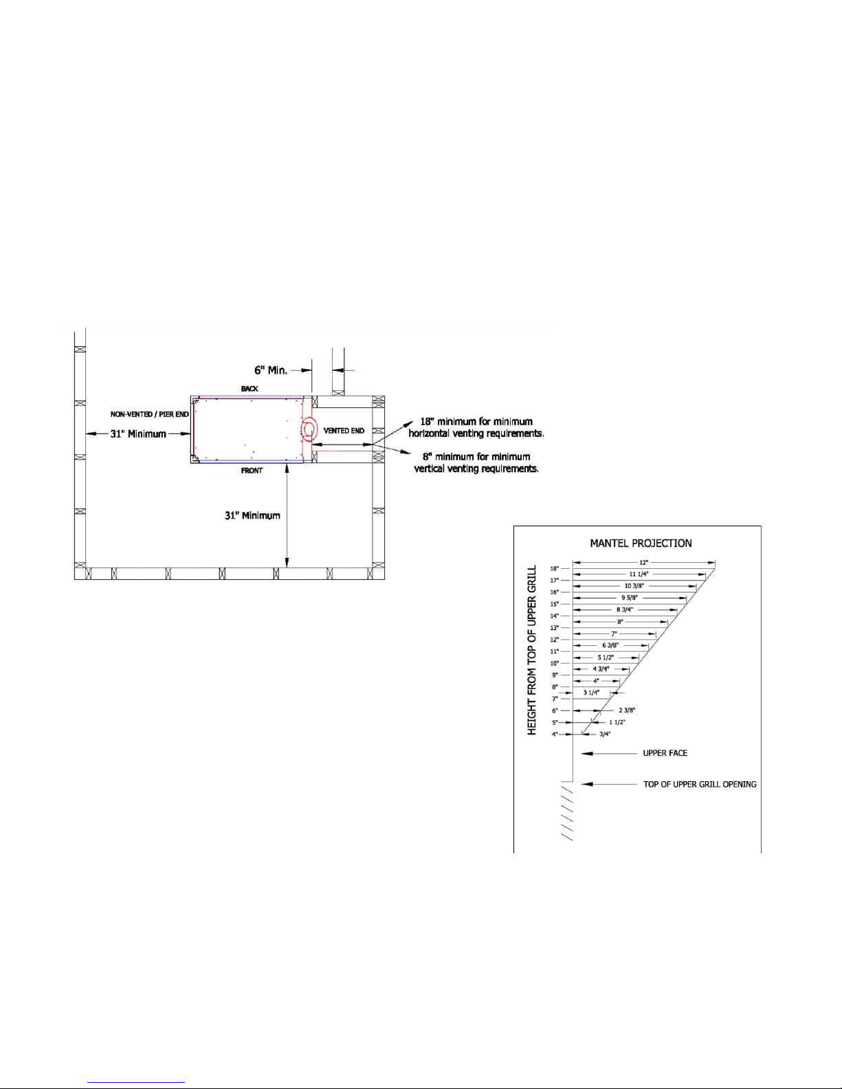
Minimum Clearance to combustibles:
- Heat Outlet Grill to Mantel: (See Diagram A)
- Unit Top : 0"
- Front / Back: 31" from parallel wall
- Floor: 0"-
- Vented End*:
0" From unit side to framing
6" From unit side to adjacent side wall
- Non-Vented End: See-Thru Installations: 0"
Pier Installations: 31"
HORIZONTAL TERMINATIONS:
- Flue Vent Top / Bottom: 2"
- Flue Vent Sides: 1 ½"
VERTICAL TERMINATIONS (rigid pipe):
- Flue Vent Sides: 1”
GAS CONVERSIONS:
This fireplace is manufactured for use with Natural Gas. An LP Gas conversion kit, part #OCK-S49A, is included with this fireplace.
Follow instructions included with the conversion kit.
Natural Gas Conversion Kit - #OCK-S30A: Used to convert an LP millivolt board to Natural gas.
LP Gas Conversion Kit - #OCK-S49A: Used to convert a Natural Gas millivolt board to LP gas.
The conversion shall be carried out in accordance with the requirements of the provincial authorities have jurisdiction and in accordance with the requirements
of the ANSI Z223.1 installation code.
Diagram A
PAGE 6
PREPARE THE FIREPLACE
Note: This fireplace is shipped as a standard see-thru model. When a pier model is desired, a pier conversion kit is used and
installed later in this manual.
Follow the instructions below for glass assemblies, regardless of which model you are installing:
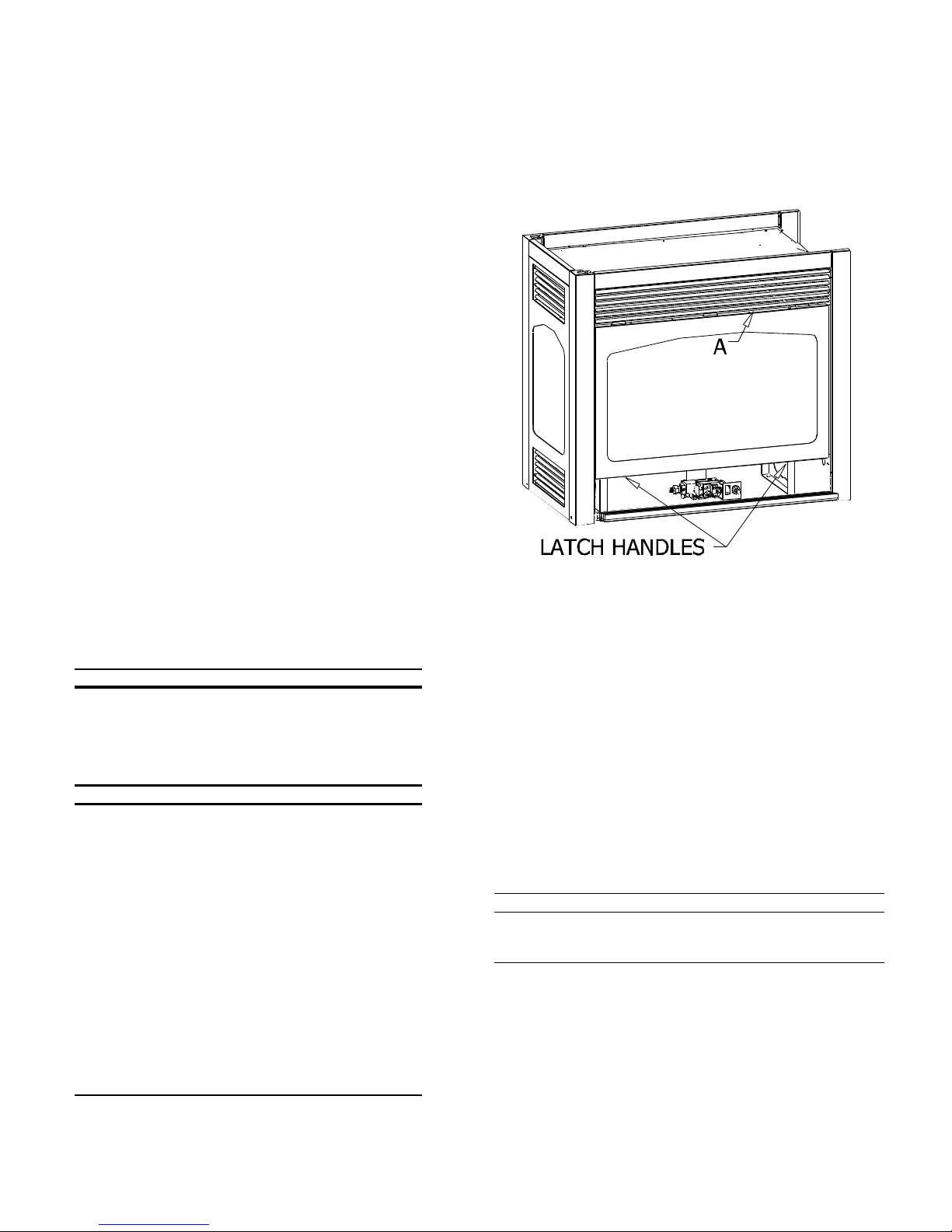
REMOVE THE GLASS ASSEMBLY: Figure 2.
Figure 2
FIREPLACE ‘FRONT’ SIDE:
A. Locate the spring-loaded handles securing the glass assembly (under the
firebox).
B. Pull the handles out, then down to release the glass assembly.
C. Pull the bottom of the glass assembly out and lift up off the tabs at the top
(A).
D. Set aside where it will not be broken.
FIREPLACE ‘BACK’ SIDE:
A. Locate the latches securing the glass assembly (under the firebox).
B. Flip the back of the latch down to release the glass assembly.
C. Pull the bottom the glass assembly out and lift up off the tabs at the top (A).
D. Set aside where it will not be broken.
C) POSITION THE FIREPLACE. See Figures 3, 4A, 4B, & 4C.
1. Determine the exact position of your fireplace, vent run and vent
termination cap location.
HORIZONTAL TERMINATIONS
IMPORTANT: The vent termination cap location must comply with
the clearances as shown on page #9. A firestop adaptor is included
with this fireplace and must be used in conjunction with the chimney
system firestop / wall thimble to ensure proper clearances are maintained when the chimney passes thru the wall.
VERTICAL TERMINATIONS
Refer to instructions included with the chimney system for positioning the chimney .
NOTE: Even though the minimum clearance from the top and sides
is 0 ", we recommend that you allow an expansion space of 1/4"
from the top & sides to prevent cracking of face materials due to
expansion of the unit during heating. If expansion room is not left,
the unit will make a loud „banging‟ noise when it heats up or cools
down.
NOTE: When the unit is installed directly on carpeting, tile, or other
combustible materials other than wood flooring, it must be installed
on a metal or wood panel extending the full width and depth of the
unit. The minimum for the support platform under the unit is 20"
deep by 36" wide. If masonry is to be used (optional), prepare the
necessary foundation for the masonry load. When masonry construction is being used, a lintel must be used over the top of the unit
to support the added weight.
NOTE: A hearth is not required. If a hearth is desired, combustible materials
may be used.
CAUTION: COLD AIR TRANSFER AREA. The surrounding outside wall
must be insulated to prevent cold air from entering the room.
Provide for a minimum of 6" of clearance in front of the lower grill. This will
provide adequate space to open and operate the controls behind the lower
grill.
Do not obstruct the upper and lower grill areas to allow proper ventilation air
around the fireplace. Room air enters the convection passageway at the
lower grill, and exits out the upper grill. DO NOT BLOCK THIS PASSAGE.
NOTE: Due to high temperatures, this unit should be located out of
traffic areas and away from furniture and draperies.
SEE-THRU INSTALLATIONS:
Rough opening dimensions differ on the „front and back sides‟. The
opening on one side must be a minimum of 38" wide to allow adequate room to slide the unit into position. See page #8.
NOTE: The control valve assembly may be rotated so that it is accessible from the opposite side from which it was manufactured. Refer to
page #15.
PAGE 7
HORIZONTAL TERMINATIONS:
1. Determine width & depth of the hearth (optional).
2. Determine the vent run and termination cap location. If possible, place the fireplace in such a manner that the piping will be placed between two studs
so additional framing is not necessary.
NOTE: Allow a minimum of 18" between the unit and inside wall to comply with minimum termination requirements. See pages #8-#11 for
horizontal termination guidelines.
3. Cut a hole for the wall thimble, 11 ½" high x 10 ½" wide. The top of this hole must be a minimum:
#700 Series Flexible Vent System: 46" * above the height of the optional hearth.
Rigid Pipe: 47 1/4" * above the height of the optional hearth.
* IMPORTANT: This measurement is determined by the vertical and horizontal length of the venting application desired. The measurement
is to the TOP of the pipe. Please refer to information below through page #14 of this installation manual for requirements and restrictions.
4. Rough in the wall enclosure.
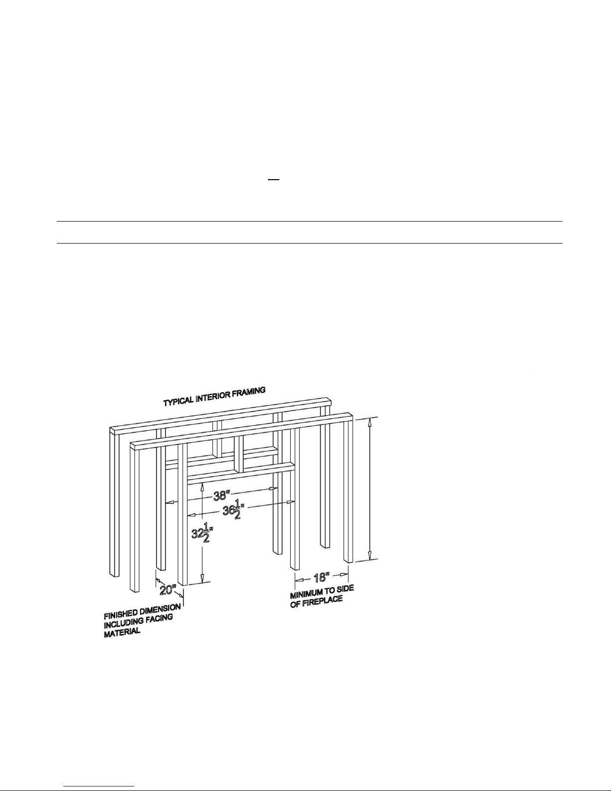
SEE-THRU INSTALLATIONS:
Rough opening dimensions are: Front face - 36 ½" wide x 32 ½" high Back face - 38" wide x 32 ½" high (above the height of the optional hearth). Depth
is determined by the thickness of face materials being used. IMPORTANT! The fireplace depth is 20". See Figure 3 below.
Figure 3
46” for 700 series flexible vent system
47-1/4” for rigid pipe applications
See-thru model shown above.
PAGE 8
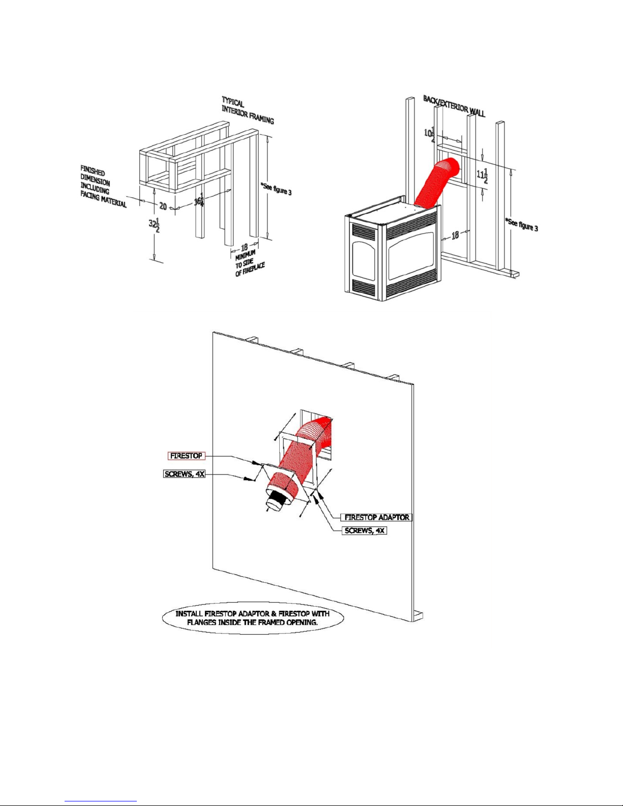
PIER INSTALLATIONS: Refer to Figures 4A & 4B. Rough opening dimensions are 36 1/4" wide x 32 1/2" high (above the height of the optional hearth).
Depth is determined by the thickness of facing materials being used. IMPORTANT! The fireplace depth is 20".
Figure 4A
Figure 4B
Pier model shown in above figures
Figure 4C
Example of Typical Firestop Adaptor, (included with the fireplace), and Firestop
(included with the #700 Series flexible chimney system) installation on a finished wall.
PAGE 9
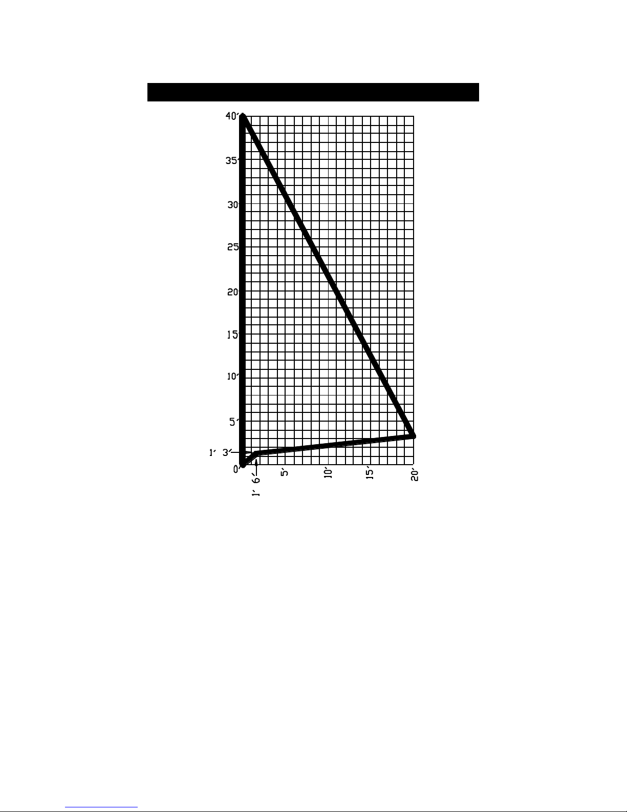
VENTING REQUIREMENTS
HORIZONTAL & VERTICAL VENTING CHART
HORIZONTAL TERMINATIONS: Minimum horizontal run: 15" (18" length of pipe)
(This is directly off the collars on the fireplace running at a 45-degree angle.)
Maximum horizontal run: 20 Ft.
Total run cannot exceed 20 Ft.
The first 15" of horizontal run must maintain a 45-degree angle. For each additional foot of horizontal run, a 1/4" rise per foot must be maintained.
VERTICAL TERMINATIONS: Maximum vertical run: 40 Ft.
Vertically position the chimney by connecting (1) 45-degree elbow onto the #923-C Dura-vent adaptor.
Connect the adaptor to the stacks on the fireplace and seal with the sealant provided.
IMPORTANT: Each installation is different and some may require a restrictor plate. Contact the dealer for more information.
Total horizontal and vertical run cannot exceed 40 Ft.
ELBOWS: 2 (90
decreased by 5-ft.
o
) Included within maximum vent runs - For each additional 90o elbow, the maximum horizontal run allowed must be
NOTE: (2) 45
.
FOLLOW THE CHART ABOVE FOR COMBINATION VENT RUNS.
o
= (1) 90
o
PAGE 10
 Loading...