

kozy heat 942 Installation & Operating Manual
U.S. PATENTS:
#5.931.154,
#5,967,139
#6,004,493
INSTALLATION & OPERATING MANUAL
#942 DIRECT VENT
DESIGN-CERTIFIED TO:
DECORATIVE & WALL FURNACE ANSI PERFORMANCE & SAFETY STANDARDS
READ INSTRUCTIONS CAREFULLY BEFORE
IMPORTANT:
INSTALLATION. FAILURE TO INSTALL THIS
FIREPLACE CORRECTLY CAN CAUSE SERIOUS
STRUCTURAL AND FIRE HAZARDS AND
MAY VOID YOUR WARRANTY.
www.kozyheat.com
June 2007

INDEX
DESCRIPTION PAGE
Safety Requirements / Specifications..................................................1-2
Venting Guidelines / Clearances....................................................... 3
Determine Location ................................................................4-5
Rough-In Vent Termination Dimensions ................................................ 5
Rough-In Dimensions................................................................ 6
Remove the Glass Assembly.......................................................... 7
Direct Vent System Installation......................................................8-13
Guidelines & Requirements for Dura-Vent GS & #800 Series Vent Systems . .. 8-10
Horizontal Termination with #800 Series D.V. Kit . . .. . . .. . . .. . . .. . . .. . . .. 11-12
Vertical Termination with #800 Series D.V. Kit . .. . . . . . . . . . . . . . . . . . . . . . . . 12-13
Fan Installation (Optional) ......................................................... 14-15
Gas Line Installation Requirements - Minimum/Maximum Pressures . . . . . . . . . . . . . . . . . . . . . . 16-17
Millivolt Board Removal / Installation................................................18-19
Log Installation.................................................................... 20
Thermostat - Remote Control - Wall Switch Installation . . . . . . . . . . . . . . . . . . . . . . . . . . . . . . . . . . . 21
Completing the Installation (Re-install the Glass Assembly, Upper & Lower Grills) . . . . . . . . . . . . . . . . . . 22
Damper Control Operation........................................................... 23
Lighting & Shutdown Procedures...................................................24-25
Manifold (outgoing) & Inlet (incoming) Pressure Check Procedures .. . . . . . . . . . . . . . . . . . . . . . . 26
Maintenance Requirements.......................................................... 27
T r o u b le s h o o t in g.................................................................28-29
Replacement Parts ................................................................. 30
Warranty Policy ................................................................. 31-32

MODEL #942 DIRECT VENT
DECORATIVE / ROOM HEATER GAS BURNING FIREPLACE
INSTALLATION & OPERATING INSTRUCTIONS
IMP O R T A N T :
READ THIS MANUAL BEFORE INSTALLING AND USING THIS FIREPLACE
INSTALLATION AND SERVICE MUST BE PERFORMED BY A QUALIFIED INSTALLER,
SERVICE AGENCY OR THE GAS SUPPLIER.
WARNING: If the information in this manual is not followed exactly, a fire or explosion may result causing property
damage, personal injury or loss of life.
This fireplace has been tested to and complies with ANSI Z 21.88!2002•CSA 2.33-M02 “VENTED GAS FIREPLACE
HEATERS”. Inst allation must confo rm with local building codes or in the absence of local building codes, with
the National Fuel Gas Code, ANSI Z223.1, NFPA 54 - Current Edition.
This appliance may be installed in a n aftermarket permanently located, manufac tured (mo bile) home, where n ot
prohibited by local codes. This appliance is only for use with the type(s) of gas indicated on the rating plate.
This appliance is not convertible for use with other gases, unless a certified kit is used.
FOR YOUR SAFETY
WHAT TO DO IF YOU SMELL GAS
Open windows.
Extinguish any open flame.
Do not try to light any appliance.
Do not touch any electrical switch; do not use any phone in your building.
Immediately call you gas supplier from a neighbor’s phone. Follow the gas supplier’s
instructions.
If you cannot reach your gas supplier, call the fire department.
Do not store or use gasoline or other flammable vapors and liquids in the vicinity of this or
any other appliance.
COMMONWEALTH OF MASSACHUSETTS INSTALLATIONS:
WARNING: This Product Must Be Installed By A Licensed Plumber Or Gas Fitter When Installed Within the
Commonwealth of Massachusetts.
IMPORTANT: Installation of a CO detector is required in the fireplace room.
Page 1
WARNING: Do not use this fireplace if any part has been under water. Immediately call a qualified service
technician to inspect this appliance and to replace any part of the control system and any gas control which
has been under water.
WARNING: DO NOT REPLACE THE BURNER WITH ANY OTHER SIZED BURNER. REPLACEMENT WITH AN
UNAUTHORIZED BURNER CAN RESULT IN TEMPERATURES EXCEEDING THE LIMITS FOR THIS
FIREPLACE, AND VOID YOUR WARRANTY.
IMPORTANT:
NON-COMBUSTIBLE FACI NG MATERIAL MAY BE APPLIED OVER THE FACE. TO PREVENT THE
FACING MAT ERIAL FROM CRA CKIN G AND FAL LING OF F DUE TO EXPA NSION OF THE FAC E WHE N
HEATED, DO NOT ATTACH FACING MATERIAL DIRECTLY TO THE FACE OF THE FIREPLACE.
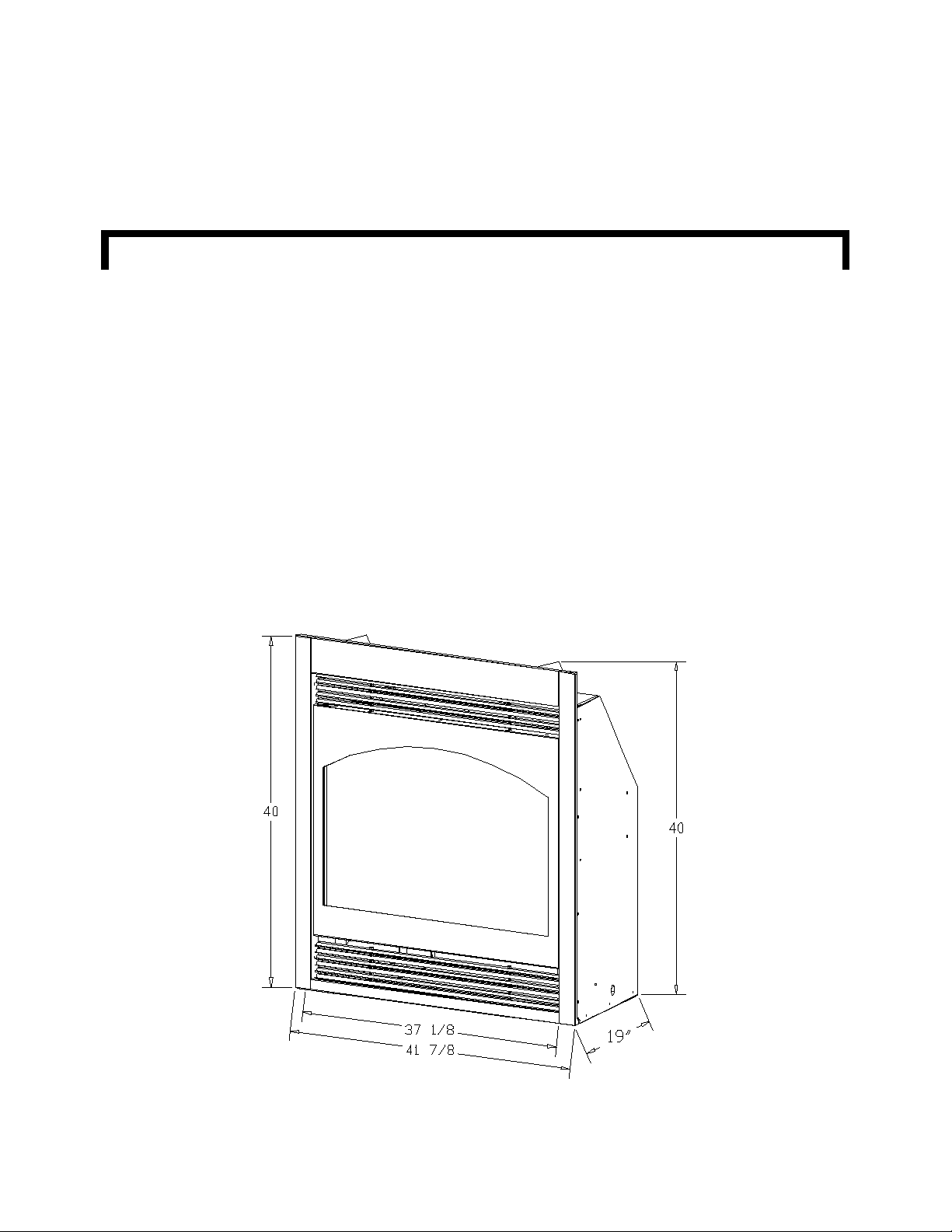
FIREPLACE SPECIFICATIONS -
HEIGHT (TOP OF FACE): 40"
HEIGHT (TOP OF STAND-OFF): 40"
FRONT WIDTH: 41 7/8"
BACK WIDTH: 31"
DEPTH (INCLUDES FACE): 19"
FLUE SIZE: 5" exhaust, 8" intake
Page 2
VENTING GUIDELINES
IMPORTANT: THIS FIREPLACE IS APPROVED FOR USE ONLY WITH ONE OF THE FOLLOWING
DIRECT VENT SYSTEMS. THESE SYSTEMS MAY BE USED FOR HORIZONTAL OR
VERTICALTERMINATIONS.
- #844 DIRE CT V E N T T E RMINAT IO N KIT - fo r te rminatio n s o f 3 ' or le s s.
- #84 5 DIR ECT VEN T TE RM INAT ION K IT - for te r mina tio ns gr e a te r th a n 6' bu t le s s th a n 8 '.
- #846 DIRECT VENT EXTENSION KIT-6'
- SIMPSON DURA-VENT DV-GS DIRECT VENT CHIMNEY SYSTEM - 5" X 8"
- AMERI-VENT DIRECT VENT CHIMNEY SYSTEM - 5" X 8"
Refer to pages #8- #13 for complete venting installation instructions / requirements.
CLEARANCES:
Minimum clearance to combustible material:
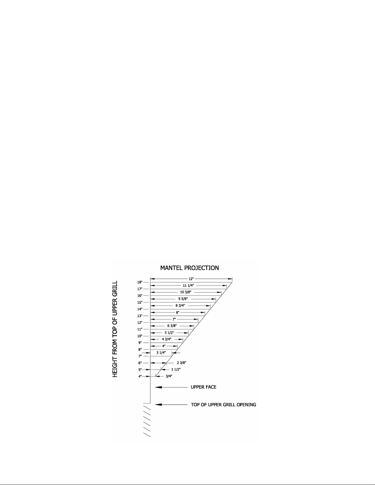
From fireplace sides & back: 0" From heat outlet to 8" mantel (or see Figure 1): 13"
From fireplace top stand-off: 0" From glazing (glass) to adjacent sidewall: 12"
To flooring: 0" From fireplace to enclosure ceiling: 4"
From #800 Series flexible chimney: 2" From Dura-Vent chimney system: 1"
NOTE: Even though the minimum clearance from the si des and back is 0", we recommend that you allow an expansion
space of 1/4" from the sides and back. If this expansion space is not left, the fireplace will make a loud
‘banging’ noise when it heats up or cools down and cracking of any face material used may occur.
Figure 1
Page 3

A) DETERMINE LOCATION - Figure 2A.
1. Determine the exact position of your fireplace. If possible place the fireplace in such a manner
that the piping will be placed between two studs so additional framing is not necessary.
2. This fireplace may be installed on either the outside or inside of an exterior wall . See Figure 2A.
The location of doors, windows, soffits / overhangs, etc. must be considered in relation to where
the vent termination cap is to be located. Refer to Figure 2B, page #5.
3. Ensure the proper clearances are maintained as outlined on page #3.
4. If the optional heat ducts are used, their location must be considered in relation to the location of
the fireplace.
The heat ducts may be vented into the same room as the fireplace or may be vented to other
rooms. A maximum run of 20 ft. for each duct is recommended.
Venting should be completed before framing the fireplace in. Refer to instructions included in the
#970 duct kit for complete installation requirements.
CAUTION: THE SURROUNDING WOOD CHASE OF THE OUTSIDE WALL MUST BE
INSULATED TO PREVENT COLD AIR FROM ENTERING THE ROOM.
NOTE: Due to high temperatures, this fireplace should be located out of
traffic areas and away from furniture and draperies.
Figure 2A
MODEL #942 DIRECT VENT
NOTE: * = 1/4" CLEARANCE
Page 4
TERMINATION VENT CAP LOCATION:
This gas appliance must not be connected to a chimney flue serving another type of appliance.
IMPORTANT!
Horizontal Terminations using either the #800 Se ries Di rect Ve nt Syst em, Simp son Dura-Vent DV-GS Chimney System or Ameri-Vent Direct
Vent System must follow the clearances to doors, windows, and ground level as shown below for proper vent cap location.
GENERAL:
1. Terminations against vinyl siding must use a vinyl siding protector. Follow instructions included.
2. DO NOT RECESS TERMI N A TIO N K IT I N TO O U TSI D E B U ILDING MATER IALS - i.e.: brick, stone, etc.. If necessary, extend framing so
that termination kit will be exposed once building materials are installed.
3. Vent termination must not be located where it will become plugged by snow or other material. The flow of combustion and ventilation air
must be not obstructed.
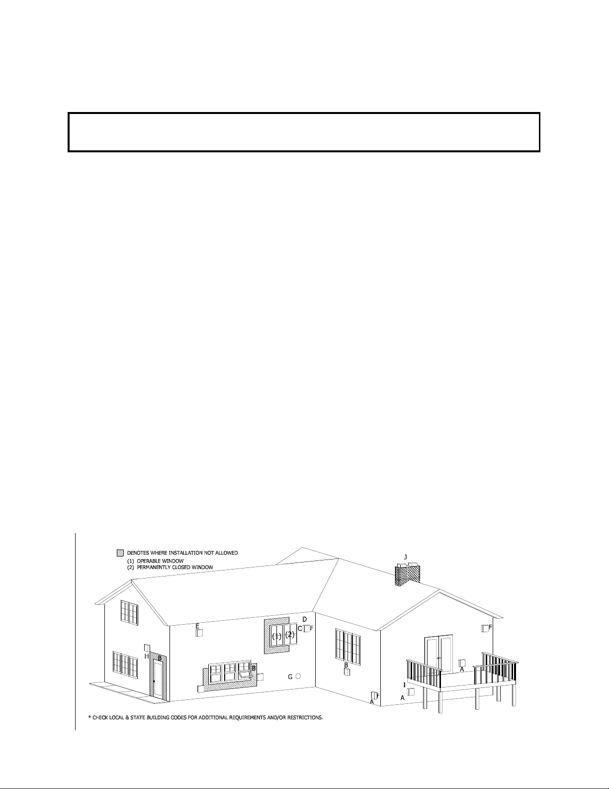
LOCATION CLEARANCES:
S Above grade, veranda, porch, deck, balcony - 12". (A)
S Operable window - 12". (B)
S Permanently closed window - 12" (recommended to prevent condensation on window. (C)
S Ventilated soffit - 24". (D)
S Unventilated soffit - 12". (E)
S Outside / inside corner - 12". (F)
S Meter / Regulator: not to be installed above within 3 ft. horizontally from the center line of the regulator.
S Service regulator vent outlet - 3 ft. radius.
S Non-mechanical air supply inlet to building - 12".
S Combustion air inlet to any other appliance - 12".
S Mechanical air supply inlet (G) - US: 3 ft. above if within 10 ft. horizontally.
NOTE: Massachusetts installations: 10 ft.
S Above furnace exhaust or inlet - 12".
S Above paved side-walk or paved driveway located on public property - 7 ft. * (H)
NOTE: A vent cannot be located directly above a side-walk or paved driveway that is located between two single family dwellings
and serves both dwellings.
S Under veranda, porch, deck, or balcony (must be fully opened on a min. of 2 sides) - 12". (I)
S Between two horizontal terminations - 12".
S Between two vertical terminations - 12" (J) - Note: May be the same height.
*Clearance must be in accordance with local installation codes and the requirements of the gas supplier.
Figure 2B
Page 5
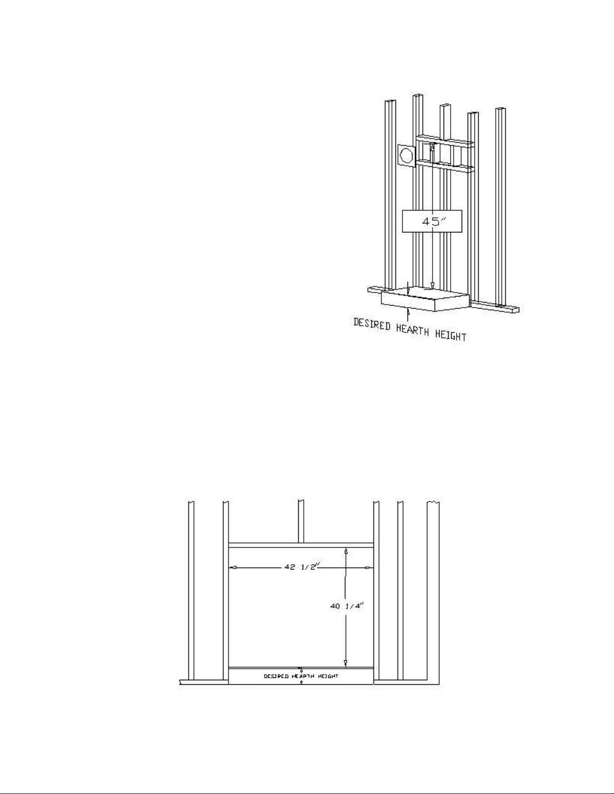
B) FRAME & POSITION THE FIREPLACE
1. Frame an opening for the firestop / wall thimble. The location of this opening is determined by your venting
specifications. Refer to the information below.
Figure 3
TYPICAL HORIZONTAL INSTALLATIONS:
Dimensions are 12 1/2" wide x 12 1/2" high when using the #800
series direct vent kits and 11" X 11" when using the Dura-Vent
chimney system. The top of this opening m ust be a m inim um of
45" * above the height of the hearth (optional). See Fig. 3. Refer to
pages #8-#13 for additional venting specifications.
*IMPORTANT: This measurement is determined by the vertical
heig h t a n d ho riz o n ta l le n g th of the ve n ting a p p lic a tio n de sire d.
The measurement is to the TOP of the pipe. Refer to pages
#8 - #13 of this installation manual for requirements and
restr i ct i ons.
2. Rou g h in the w all enclo su re. The minimum rough
opening dimensions are 42 1/2" wide, 40 1/4" high and 21"
deep. Build the hearth to the desired size and height. See
Figure 4.
NOTE: When the fireplace is installed directly on carpeting, tile, or other combustible materials other than wood flooring, it must be
installed on a metal or wood panel extending the full width and depth of the fireplace. The minimum for the support platform under
the fireplace is 42" wide by 19" deep. If masonry is to be used, (optional), prepare the necessary foundation for the masonry load.
Wh en mas o nry c o n stru c tio n is b e ing u se d , a linte l must b e u se d o v er the top o f th e firep la ce to s u pp o rt th e a d d e d w e igh t.
NOTE: A hearth is not required. If a hearth is desired, combustible materials may be used.
NOTE: P ro v id e for a minim u m of 6 " o f cle a ra n ce in fro n t o f the lo w e r g rill. Th is will provid e a de q u a te sp a c e fo r o p en in g to
ope r a te th e co n trol valv e . Do n o t obs tru c t the u p p e r a n d lo wer g rill a r e a s to a llo w pro p er ve n tila tion a ir a r o u n d the firepla c e . A ir
enters the fireplace at the lower grill and exits at the upper grill. Do not block this passage.
Figure 4
3. Place the fireplace into position.
Page 6
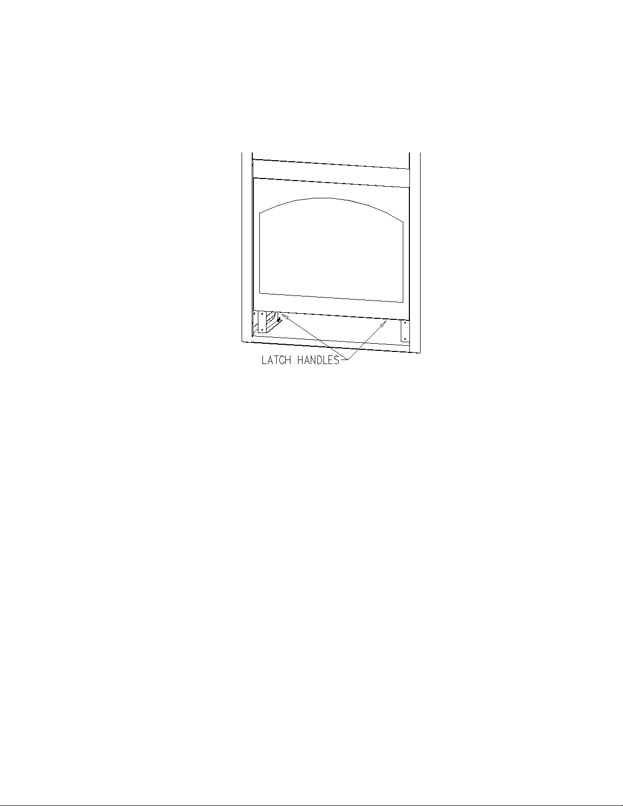
4. REMOVE THE GLASS ASSEMBLY.
A. Locate the spring-loaded h an dles securing the glass ass embly (under the firebox).
B. Pull the latch handles out, then down to release the glass assembly.
C. Pull the bottom of the glass assembly out and lift up off the tabs at the top.
D. Set aside where it will not be broken.
E. Remove the log package and klinkers from inside the firebox & set aside for later installation.
Figure 5
Page 7
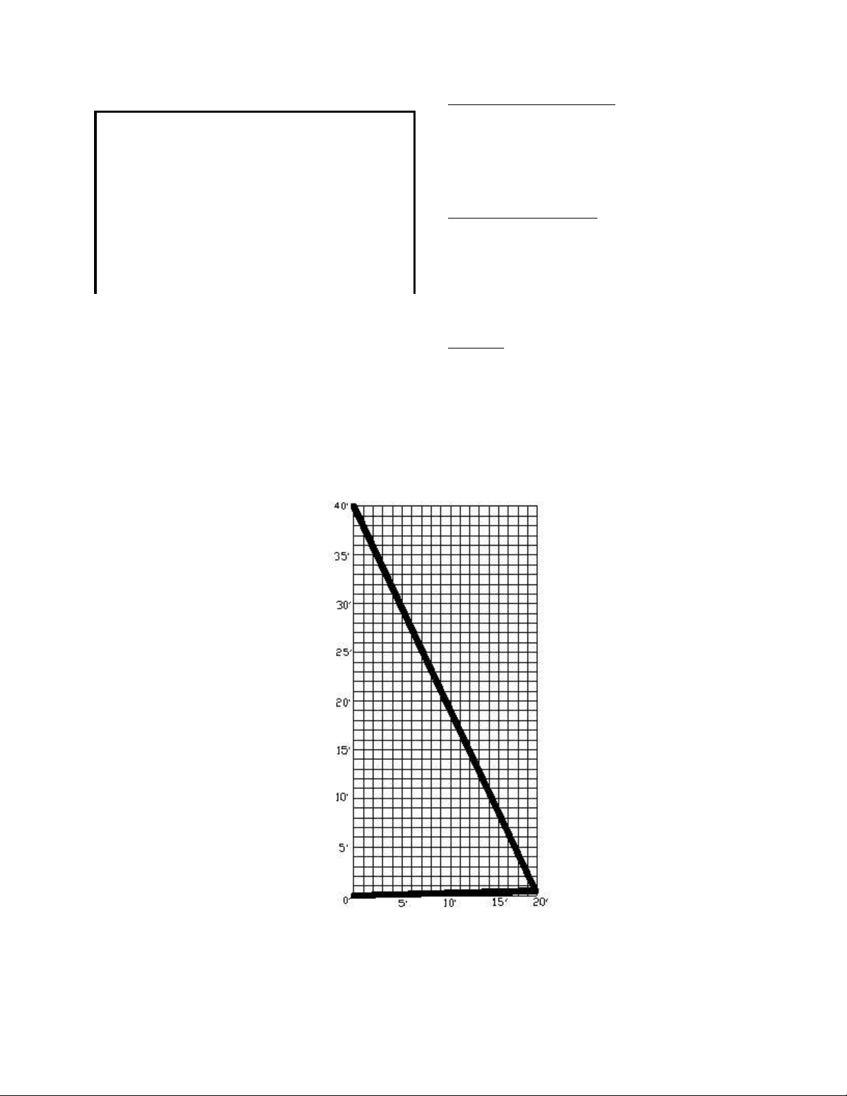
C) VENTING REQUIREMEN TS
HORIZONTAL TERM INATIONS:
IMPORTANT: THIS FIREPLACE IS APPROVED
FOR USE ONLY WITH ONE OF THE FOLLOWING
DIRECT VENT SYSTEMS.
Note: We recommend using the #800 series direct
vent system for horizontal vent runs only. The
Simpson Dura-Vent DV-GS & AMERI-VENT DIRECT
VENT 5" x 8" systems may be used for both horizon tal
and vertical vent runs.
- #844 DIRECT VENT TERMINATION KIT - for vent
runs 3' or less.
- #845 DIRECT VENT TERMINATION KIT - for vent
runs greater than 6' but less than 8'.
- #846 DIRECT VENT EXTENSION KIT - 6'
- SIMPSON DURA-VENT DV-GS DIRECT VENT
CHIMNEY SYSTEM - 5" x 8".
- AMERI-VENT DIRECT VENT SYSTEM - 5" X 8".
Minimum 6" run directly from appliance outlet, followed by a
45-d e gree elb o w .
Minimum horizontal run outlet: 6"
Maximum Horizontal run: 20 ft. (with 1/4" per foot incline)
VERTICAL TERMINATIONS:
Attach a 45 -degre e e lb o w d ire ctly o n to a p p lian c e o u tle t.
Ma ximum v e rtica l rise fro m ap p lian c e ou tle t: 4 0 ft.
IMPORTANT: Straight vertical terminations must use
the in c lu d e d res tr ic to r plate fo r v e n t runs 1 5 ' - 4 0 '.
ELBOWS:
o o
(1) 45 elbow at start & (2) 90 elbows included within the
maximum vent runs. Each additional elbow reduces the
ma ximum h o riz o n tal d ista n c e b y 5 '.
FOR SIMPS ON DU R A-VEN T D V-GS & AMERI-VENT 5” X
8” DIREC T V EN T SY ST EMS - Follow installation
instructions included with the vent system.
Vertical Termination: A 45-degree
elbow may be attached directly to
the fireplace and run a maximum of
40 ft. 2 - 90-degree elbows may be
used within the 40 ft. vertical vent run.
Vent runs of 15' - 40' must install the
restrictor plate included with this
fireplace.
Figure 6 20 FT. MAX. HORIZONTAL RUN
Horizontal terminations: The minimum vent run directly off the fireplace is 6". Connect to a 45degree elbow prior to attaching to the fireplace to ensure the chimney is positioned
horizontally. 2 - 90- degree e lbows may be used wit hin the maxi mum 20 ft. hori zontal ve nt run.
For each additional elbow, the maximum horizontal distance must be reduced by 5'.
IMPORTANT:
1/4" RISE PER HORIZONTAL
FOOT MUST BE MAINTAINED.
Page 8
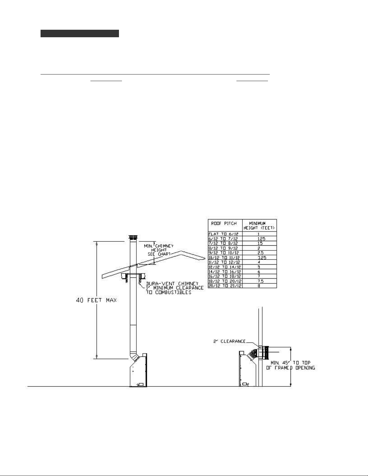
VERTICAL TERMINATIONS:
WHEN VERTICALLY TERMINATING THE MINIMUM CHIMNEY HEIGHT ABOVE THE ROOFLINE IS
DETERMINED BY THE FOLLOWING CHART:
Roof Pitch Minimum Height Roof Pitch Minimum Height
above roof line above roof line
Flat to 6/12 1 ft. 11/12 to 12/12 4 ft.
6/12 to 7/12 1 ft. 3 in. 12/12 to 14/12 5 ft.
7/12 to 8/12 1 ft. 6 in. 14/12 to 16/12 6 ft.
8/12 to 9/12 2 ft. 16/12 to 18/12 7 ft.
9/12 to 10/12 2 ft. 6 in. 18/12 to 20/12 7 ft. 6 in.
10/12 to 11/12 3 ft. 3 in. 20/12 to 21/12 8 ft.
IMPORTANT: VERTICAL TERMINATIONS USING THE #800 SERIES FLEXIBLE CHIMNEY SYSTEMS REQUIRE A SUPPORTING CHASE
TO BE BUILT AROUND THE CHIMNEY ABOVE THE ROOF LINE. A 2" CLEARAN CE TO COMBUSTIBLE MATERIALS M UST
BE MAINTAINED AROUND THE PIPE.
EXAMPLE OF TYPICAL HORIZONTAL & VERTICAL TERMINATIONS
Figure 7A
Note: Simpson Dura-Vent Note: Kozy Heat Direct Vent System
chimney system shown in shown in horizontal termination.
vertical termination.
Page 9
 Loading...