

kozy heat 936 Installation & Operating Manual
PATENT PENDING
INSTALLATION & OPERATING MANUAL
#936 DIRECT VENT
WALL FURNACE
READ INSTRUCTIONS CAREFULLY BEFORE I NSTALLATION.
FAILURE TO INSTALL THIS FIREPLACE CORRECTLY CAN
CAUSE SERIOUS STRUCTUAL AND FIRE HAZARDS AND
MAY VOID YOUR WARRANTY
IMPORTANT:
.
www.kozyheat.com
MAY 1998

INDEX
DESCRIPTION
PAGE
SAFETY REQUIREMENTS / SPECIFICATIONS ............................ 2-3
MINIMUM CLEARANCES ...............................................3
GAS CONVERSIONS ..................................................3
PREPARE THE UNIT ...................................................4
POSITION THE UNIT................................................. 5-6
ROUGH-IN CHIMNEY VENT DIMENSIONS .............5
ROUGH-IN DIMENSIONS ...........................6
VENTING REQUIREMENTS .......................................... 7-10
DIRECT VENT KIT INSTALLATION ......................................10
FAN INSTALLATION ............................................... 11-12
GAS LINE SPECIFICATIONS ........................................ 13-14
MILLIVOLT BOARD REMOVAL / INSTALLATION ........................15-16
LOG INSTALLATION ............................................... 16-17
WALL SWITCH - THERMOSTAT - REMOTE CONTROL INSTALLATION.........18
COMPLETE THE INSTALLATION........................................19
LIGHTING & SHUTDOWN........................................... 20-21
MANIFOLD & INCOMING PRESSURE CHECK PROCEDURES ................22
CLEANING & MAINTENANCE REQUIREMENTS............................23
TROUBLE SHOOTING ............................................. 24-25
REPLACEMENT PARTS LISTS
..................................... 26
IMPORTANT:
Page 1
READ THIS MANUAL BEFORE INSTALLING AND USING THIS FIREPLACE
MODEL #936 DV WALL FURNACE
INSTALLATION INSTRUCTIONS
This appliance has been tested to and complies
with ANSI Z21.44-1993, “GAS-FIRED DIRECT VENT
WALL FURNACES”, and applicable sections of
ANSI Z21.50-1996 “VENTED DECORATIVE
APPLIANCE”. Installation must conform with local
building codes, or, in the absence of local building
codes, with the national fuel gas code, ANSI
Z223.1-1992 NFPA 54, or the Manufactured Home
Construction and Safety Standard, Title 24 CFR,
Part 3280.
INSTALLATION AND/OR REPAIR OF THIS UNIT SHOULD ONLY BE
DONE BY A QUALIFIED INSTALLER
.
WARNING: Do not use this heater if any part
has been under water. Immediately call a
qualified service technician to inspect the
appliance and to replace any part of the control
system and any gas control which has been
under water.
WARNING: DO NOT REPLACE THIS BURNER
UNIT WITH ANY OTHER SIZED BURNER.
REPLACEMENT WITH AN UNAUTHORIZED
BURNER CAN RESULT IN TEMPERATURES
EXCEEDING THE LIMITS FOR THIS UNIT, AND
VOID YOUR WARRANTY.
WARNING: If the information in this manual is not
followed exactly, a fire or explosion may result causing
property damage, personal injury or loss of life.
FOR YOUR SAFETY: WHAT TO DO IF
YOU SMELL GAS:
! Do not touch any electrical switches.
! Do not try to light any appliance.
! Do not use the phone in your building.
! Immediately call you gas supplier from a
neighbor’s phone.
! Follow the gas suppliers instructions.
! If you cannot reach your gas supplier, call
the fire department.
! Do not store or use gasoline or other
flammable vapors and liquids in the
vicinity of this or any other appliance.
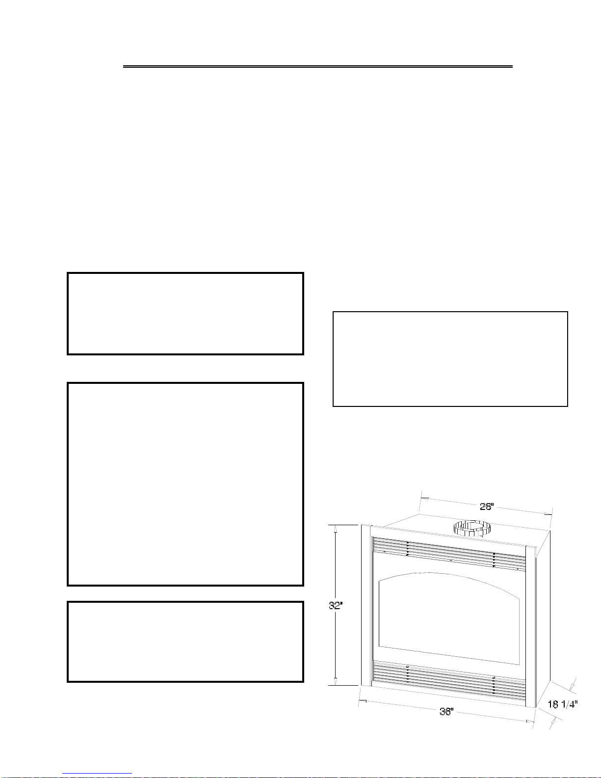
UNIT SPECIFICATIONS Height: 32"
Front width (w/o face): 36"
Back width: 26"
Depth(incl. face): 18 1/4"
Face to front of 7” intake 11 1/4”
Flue size: 4" exhaust, 7" intake
WARNING: Improper installation, adjustment,
alteration, service or maintenance can cause
injury or property damage. Refer to this
manual. For assistance or additional
information consult a qualified installer,
service agency, or the gas supplier.
Page 2

IMPORTANT: THIS UNIT IS APPROVED FOR USE ONLY WITH ONE OF THE FOLLOWING DIRECT VENT
SYSTEMS :
- #745 DIRECT VENT TERMINATION KIT - for
terminations 4' for less.
- SIMPSON DURA-VENT DV-GS DIRECT VENT
CHIMNEY SYSTEM: 4” x 6 5/8”. For vertical
terminations.
- #718 DIRECT VENT TERMINATION KIT - for
terminations greater than 4' but less than 8'.
*Adaptor #923-C is required to adapt the flue
collars to the chimney.
- #746 DIRECT VENT EXTENSION KIT - used in
conjunction with #745 or #718. The extension kit is
expandable to 6'.
Refer to pages #7 - # 11 for complete venting installation
instructions / requirements
.
For visual inspection of proper vent connection; upon completion of installing the direct vent kit, remove the nuts and
the baffle inside the unit to expose the lower end of the flue gas exit.
IMPORTANT: NON-COMBUSTIBLE FACING MATERIAL MAY BE APPLIED OVER THE FACE. TO PREVENT THE FACING
MATERIAL FROM CRACKING AND FALLING OFF DUE TO EXPANSION OF THE FACE WHEN HEATED, DO NOT ATTACH
FACING MATERIAL DIRECTLY TO THE FACE OF THE UNIT.
CLEARANCES Mantel Projection
Minimum clearance to combustibles, see Figure 1:
From unit sides & back: 0"
From unit top stand-off: 0"
To flooring: 0"
From flue vent: 1"
From unit glazing to adjacent sidewall: 8"
From heat outlet to mantle: 12"
GAS CONVERSIONS
If a gas conversion is necessary, one of the following conversions kits must be used:
OCK-331- Natural Gas Converisons Kit - used to convert an LP Millivolt
board to natural gas.
OCK-349 - LP Gas Conversion Kit - used to convert a Natural Gas
Millivolt board to LP Gas.
The conversion shall be carried out in accordance with the requ irements of the provincial authorities having
jurisdiction and in accordance with the requirements of the ANSI Z223.1 installation code.
A) PREPARE THE UNIT
Page 3
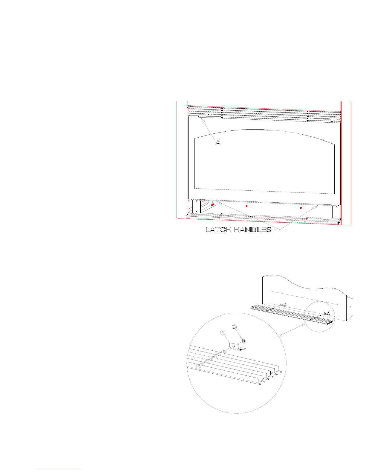
1. REMOVE THE UPPER GRILL
A. Remove the upper grill (A) by lifting it up far
enough to clear the bottom holes and pull the
bottom of the grill out.
2. REMOVE THE GLASS ASSEMBLY.
See Figure 3.
A. Open the lower grill and locate the spring-
loaded handles securing the glass
assembly (under the firebox).
B. Pull the handles out, then down to release the
glass assembly.
C. Pull the bottom of the glass assembly out and
lift up off the tabs.
D. Set aside where it will not be broken.
E. Remove the box of logs from the firebox and
set aside.
Figure 1
3. REMOVE THE LOWER GRILL.
(FOR OPTIONAL FAN INSTALLATION).
A. Grasp the center of the lower grill and pull
down to open.
B. Remove the 1/4” nuts (B) from the grill
assembly.
C. Pull the entire assembly out of the hinges(A).
D. Re-attach the 1/4” nuts (B) to the grill
assembly and set aside for reinstallation later
in this manual.
Figure 2
Page 4
B) POSITION THE UNIT. See Figure 3.
1. Determine the exact position of your fireplace.
If possible, place the fireplace in such a manner
that the piping will be placed between two studs so
additional framing is not necessary. Determine the
width and depth of the (optional) hearth.
2. The unit may be installed on either the outside
or inside of an exterior wall. See Figure 1 for
various installation options. Follow clearance
requirements listed above.
CAUTION: COLD AIR TRANSFER AREA. THE
SURROUNDING WOOD CHASE OF THE
OUTSIDE WALL MUST BE INSULATED TO
PREVENT COLD AIR FROM ENTERING THE
ROOM.
NOTE: Due to high temperatures, this
unit should be located out of traffic areas
and away from furniture and draperies.
Figure 3
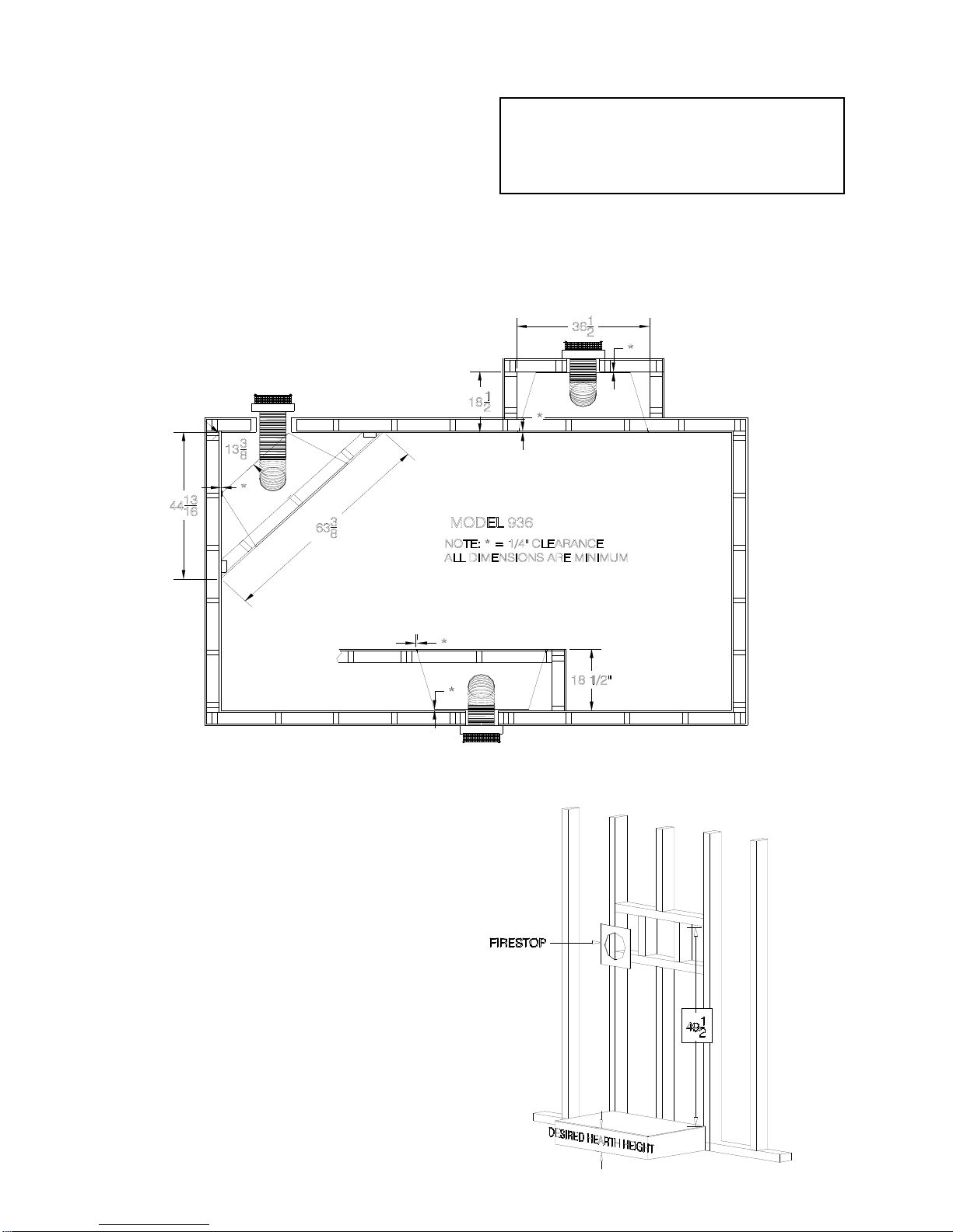
3. Cut a hole for the firestop, 9 1/2" x 9 1/2". The top
of this hole must be a minimum of 49 1/2" * above
the height of the hearth (optional). See Figure 4A.
*Important: This measurement is
determined by the vertical height and
horizontal length of the venting
application desired. The measurement
is to the top of the pipe. Please refer to
page #7 of this installation manual for
requirements and restrictions.
Fig. 4A
Page 5
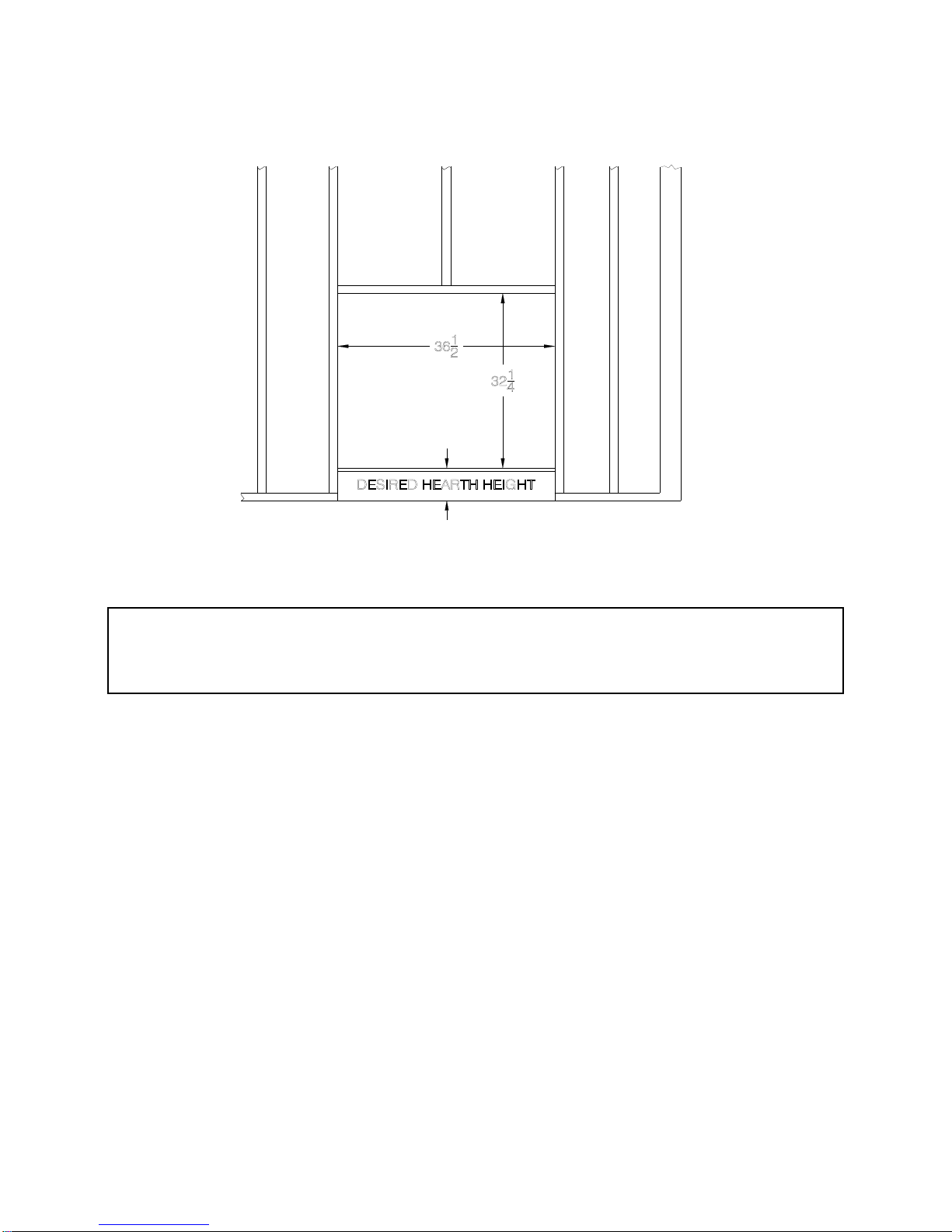
4. Rough in the wall enclosure. The minimum rough opening dimensions are 32 1/4" high,
36 1/2" wide and 18 1/2" deep. Build the hearth to the desired size, and height. See Fig. 4B.
Figure 4B
NOTE: When the unit is installed directly on carpeting, tile, or other combustible materials other than wood flooring, it
must be installed on a metal or wood panel extending the full width and depth of the unit. The minimum for the support
platform under the unit is 18 1/4" deep by 36" wide. If masonry is to be used (optional), prepare the necessary
foundation for the masonry load. When masonry construction is being used, a lintel must be used over the top of the unit
to support the added weight.
NOTE: A non-combustible hearth extension is not required. If a hearth extension is desired,
combustible materials may be used.
NOTE: Provide for a minimum of 6" of clearance in front of the lower grill. This will provide
adequate space for opening to open the lower grill and operate the controls.
Do not obstruct the upper and lower grill areas to allow proper ventilation air around the unit. Air
enters the unit at the lower grill, and exits at the upper grill. Do not block this passage.
5. Place the unit into position.
Page 6
C) VENTING REQUIREMENTS
IMPORTANT: THIS UNIT IS APPROVED FOR USE ONLY WITH THE FOLLOWING DIRECT
VENT SYSTEMS:
HORIZONTAL TERMINATIONS
#700 SERIES DIRECT VENT TERMINATION KITS:
- #745 KOZY HEAT DIRECT VENT KIT - For terminations of 4' or less.
- #718 KOZY HEAT DIRECT VENT KIT - For terminations greater than 4' but less than 8'.
- #746 KOZY HEAT DIRECT VENT EXTENSION KIT #746 - Used to extend the
#745 or #718 kit an additional 6'. Used for horizontal terminations.
VERTICAL TERMINATIONS
-SIMPSON DURA-VENT DV-GS DIRECT VENT CHIMNEY SYSTEM* ( 4” x 6 5/8”).
- Used for vertical terminations only.
- Adaptor #923-C is required to adapt the flue collars on the unit to the chimney system
- Vent runs must be in compliance as outlined below.
o
- 45
elbows only - Follow installation instructions included with the #923-C adaptor & chimney
system.
.
Vertical Rise
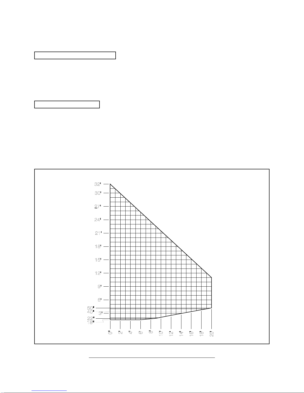
HORIZONTAL & VERTICAL VENTING CHART
HORIZONTAL VENTING REQUIREMENTS
Horizontal Run
Page 7
MINIMUM VERTICAL RISE* FROM TOP OF UNIT: 18 IN. (to top of 7” pipe)
MINIMUM HORIZONTAL RUN: 6 IN.
MAXIMUM HORIZONTAL RUN: 20 FT. (Horizontal runs must maintain 1/4” rise per ft.)
TOTAL HORIZONTAL & VERTICAL RUN MUST NOT EXCEED 32 FT.
*Miniminum vertical rise directly off the top of the unit is determined by the length of the horizontal run. Refer
to the venting diagram on page 7.
1. #700 Series vent kits must be supported every
3 ft. to maintain proper rise.
2. NOTE: IF TERMINATING AGAINST VINYL
SIDING, A VINYL SIDING PROTECTOR , INCLUDED
WITH THE #745 AND #718 DIRECT VENT KIT, MUST
BE USED. FOLLOW INSTALLATION
INSTRUCTIONS INCLUDED.
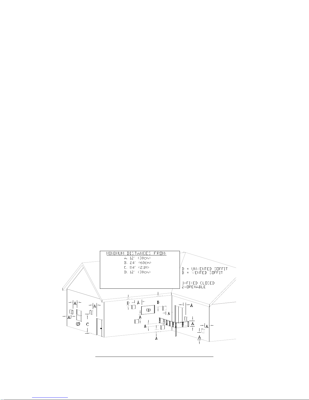
3. IMPORTANT: DO NOT RECESS
TERMINATION KIT INTO OUTSIDE BUILDING
MATERIALS - brick, stone, etc. If necessary,
extend framing so that termination kit will be
exposed once building materials are installed.
Follow Figure 5 for clearances to doors, window s
and ground level.
4. IMPORTANT: VENT TERMINATION MUST
NOT BE LOCATED WHERE IT WILL BE
BECOME PLUGGED BY SNOW OR OTHER
MATERIAL.
5. Fo r each additional elbow used after the first
elbow, you must subtract 5 ft. from the maximum
horizontal run allowed.
For example: A vertical rise of 18” directly off the top of
the unit with a 90
1/4” rise per ft.. If an additional elbow is used within this
vent run, the maximum horizontal run allowed would be
3’ ’ with 1/4” rise per ft.. (8 ft - 5 ft. (for additional elbow)
= 3 ft.
)
o
elbow would be allowed to run 8’ with
Fig. 5
VERTICAL VENTING REQUIREMENTS
Page 8
 Loading...