

kozy heat 911-XXL Operating Manual
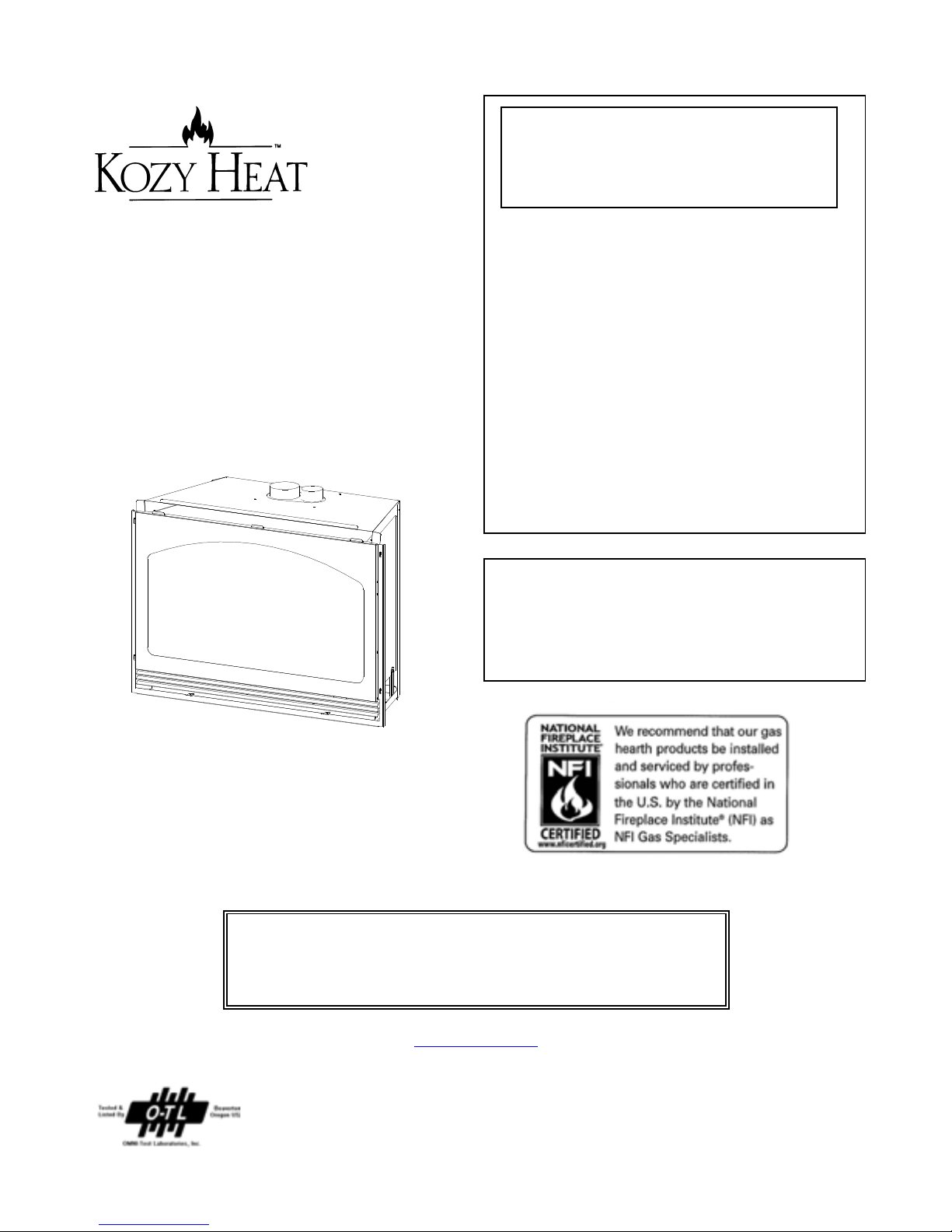
Model #911-XXL
WARNING: If the information in these
instructions are not followed exactly, a fire or
explosion may result causing property damage,
personal injury or loss of life.
Do not store or use gasoline or other flammable vapors
in the vicinity of this or any other appliance.
Direct Vent Gas Fireplace Insert
INSTALLATION & OPERATING
MANUAL
U.S. PATENT #5,931,154
U.S. PATENT #6,004,493
U.S. PATENT #6,029,655
WHAT TO DO IF YOU SMELL GAS:
‚ Do not try to light any appliance.
‚ Do not touch electrical switches; do not use the
phone in your building.
‚ Immediately call your gas supplier from a neighbor’s
phone. Follow the gas supplier’s instructions.
‚ If you cannot reach your gas supplier, call the fire
department.
- Installation and service must be performed by a qualified
installer, service agency or the gas supplier.
This appliance may be installed in an aftermarket
permanently located, manufactured (mobile) home, wher e
not prohibited by local codes.This appliance is only for
use with the type(s) of gas indicated on the rating place.
This appliance is not convertible for use with other
gases, unless a certified kit is used.
READ ALL INSTRUCTIONS CAREFULLY BEFORE INSTALLATION.
FAILURE TO INSTALL THIS FIREPLACE INSERT CORRECTLY CAN
CAUSE SERIOUS STRUCTURAL AND FIRE HAZARDS AND MAY VOID
IMPORTANT:
YOUR WARRANTY.
www.kozyheat.com
October 2006

INDEX
Fireplace Insert Specifications ...................................................... 1
Safety Requirements.............................................................. 1
Requirements of Existing Fireplace .................................................. 2
Fireplace Insert Components ....................................................... 3
Preparing The Existing Fireplace .................................................... 4
Gas Line Installation Requirements - Minimum/Maximum Pressures ..................... 4-5
Insert Preparation.............................................................. 6-7
Remove the Glass Assembly ............................................ 6
Remove the Millivolt Board ............................................. 6
Remove the Air Duct .................................................. 7
Installing the Insert ........................................................... 7-13
Restrictor Installation ................................................. 7
Co-Linear Vent System ................................................ 8
Install the Vent System................................................ 9
Position the Insert & Secure the Air Duct ................................ 10
Replace the Millivolt Board ............................................ 11
Log Installation ................................................................. 12
Assemble & Attach the Shroud .................................................. 13-15
Complete the Fan Installation ..................................................... 16
Complete the Installation -
Initial Lighting / Seasonal Heat Dump Adjustment /
Replace the Glass Assembly / Replace the Lower Grill ............................... 17
Thermostat - Remote Control - Wall Switch Installation ................................ 18
Lighting & Shutdown Procedures ................................................ 19-20
Manifold (outgoing) & Inlet (incoming) Pressure Check Procedures ....................... 21
Maintenance Requirements ....................................................... 22
Troubleshooting.............................................................. 23-24
Gas Conversion Kit ........................................................... 25-26
Replacement Parts .............................................................. 27
Warranty Policy .............................................................. 28-29
MODEL JACKSON XXL
DIRECT VENT GAS BURNING FIREPLACE INSERT
INSTALLATION & OPERATING INSTRUCTIONS
IMPORTANT:
READ THIS MANUAL BEFORE INSTALLING AND USING THIS FIREPLACE
This fireplace has been tested to and complies with ANSI Z21.88-2002CSA 2.33-2002 “VENTED GAS FIREPLACE HEATERS” by
OMNI-Test Laboratories, Beaverton, Oregon for U.S. Installations only. Installation must conform with local building codes or in
the absence of local building codes, with the National Fuel Gas code, ANSI Z223.1 NFPA 54 - Current Edition.
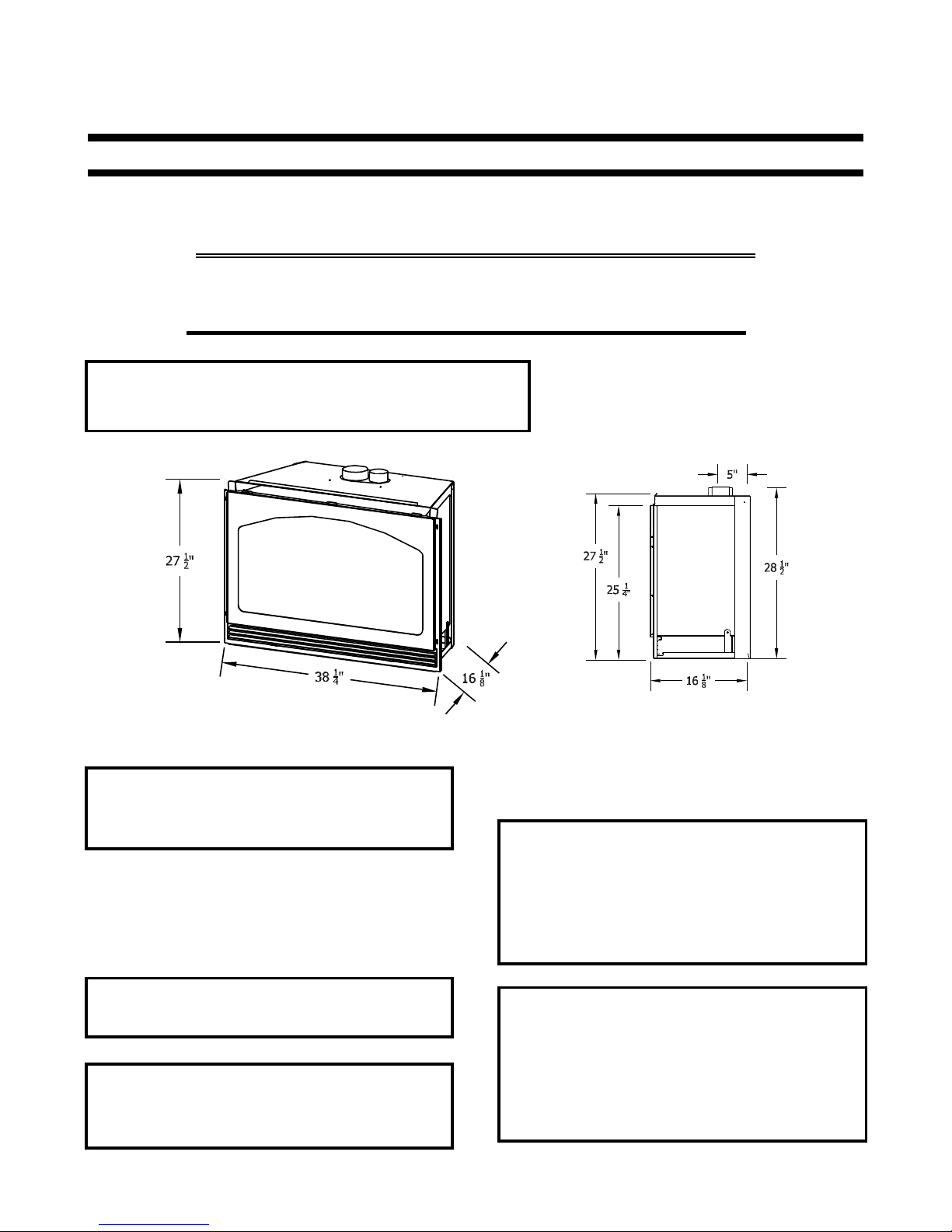
SPECIFICATIONS:
Height (top of firebox): 25 1/4" Height (top of air duct): 27 1/2"
Width: 38 1/4" Back Width: 26 1/4" Depth: 16 1/8”
NOTE: Minimum existing opening width required: 38 1/2"
Do not use this fireplace if any part has been under water.
Immediately call a qualified service technician to inspect
this appliance and to replace any part of the control
system and any gas control which has been under water.
WARNING: DO NOT REPLACE THIS BURNER WITH ANY
OTHER SIZED BURNER. REPLACEMENT WITH AN
UNAUTHORIZED BURNER CAN RESULT IN TEMPERATURES
EXCEEDING THE LIMITS FOR THIS FIREPLACE AND VOID
YOUR WARRANTY.
DUE TO HIGH TEMPERATURES, THIS FIREPLACE SHOULD
BE LOCATED OUT OF TRAFFIC AND AWAY FROM
FURNITURE AND DRAPERIES
The efficiency rating of this appliance is a product
thermal efficiency rating determined under continuous
operating conditions and was determined independently
of any installed system.
YOUNG CHILDREN SHOULD BE CAREFULLY SUPERVISED
WHEN THEY ARE IN THE SAME ROOM AS THIS FIREPLACE.
CHILDREN AND ADULTS SHOULD BE ALERTED TO THE
HAZARDS OF HIGH SURFACE TEMPERATURE AND
SHOULD STAY AWAY TO AVOID BURNS OR CLOTHING
IGNITION.
CLOTHING OR OTHER FLAMMABLE MATERIAL SHOULD
NOT BE PLACED ON OR NEAR THE APPLIANCE.
COMMONWEALTH OF MASSACHUSETTS INSTALLATIONS
WARNING: This Product Must Be Installed By A Licensed Plumber Or
Gas Fitter When Installed Within The Commonwealth of Massachusetts.
IMPORTANT: Installation of a CO detector is required in the fireplace
room.
Page 1
CAUTION: THIS FIREPLACE INSERT IS APPROVED FOR INSTALLATION IN MASONRY AND FACTORY-BUILT SOLID FUEL
BURNING FIREPLACES.
CAUTION: THIS APPLIANCE MUST NOT BE CONNECTED TO A CHIMNEY FLUE SERVING A SEPARATE SOLID-FUEL
BURNING APPLIANCE.
THE EXISTING FIREPLACE MUST MEET THE FOLLOWING REQUIREMENTS:
1. The existing fireplace & chimney must be clean and in good working order and constructed of non-combustible materials.
2. A gas line must be able to be installed to the insert.
3. Any chimney cleanouts must fit properly.
4. Existing Chimney: - Class ‘A’ metal chimney: Co-linear 3” x 4” venting - 8” minimum inside diameter.
- Masonry Chimney: Co-linear 3" x 4" venting - 6" x 8" minimum inside diameter.
Chimney height: Height of existing chimney must be at least: 11 ft.
Maximum height of existing chimney: 40 ft.
To Determine the length of your existing chimney:
A) Remove the chimney cap.
NOTE: It is helpful to have two people complete the next step in determining chimney height.
B) With one person at the fireplace and the other person at the top of the chimney, measure from the base of the fireplace to the top of
the chimney. Subtract 24” for the height of the insert. This is the total length of co-linear flexible aluminum you will require.
MEASUREMENT FROM BASE OF FIREPLACE TO TOP OF CHIMNEY: ____
TOTAL CHIMNEY LENGTH REQ.: ____
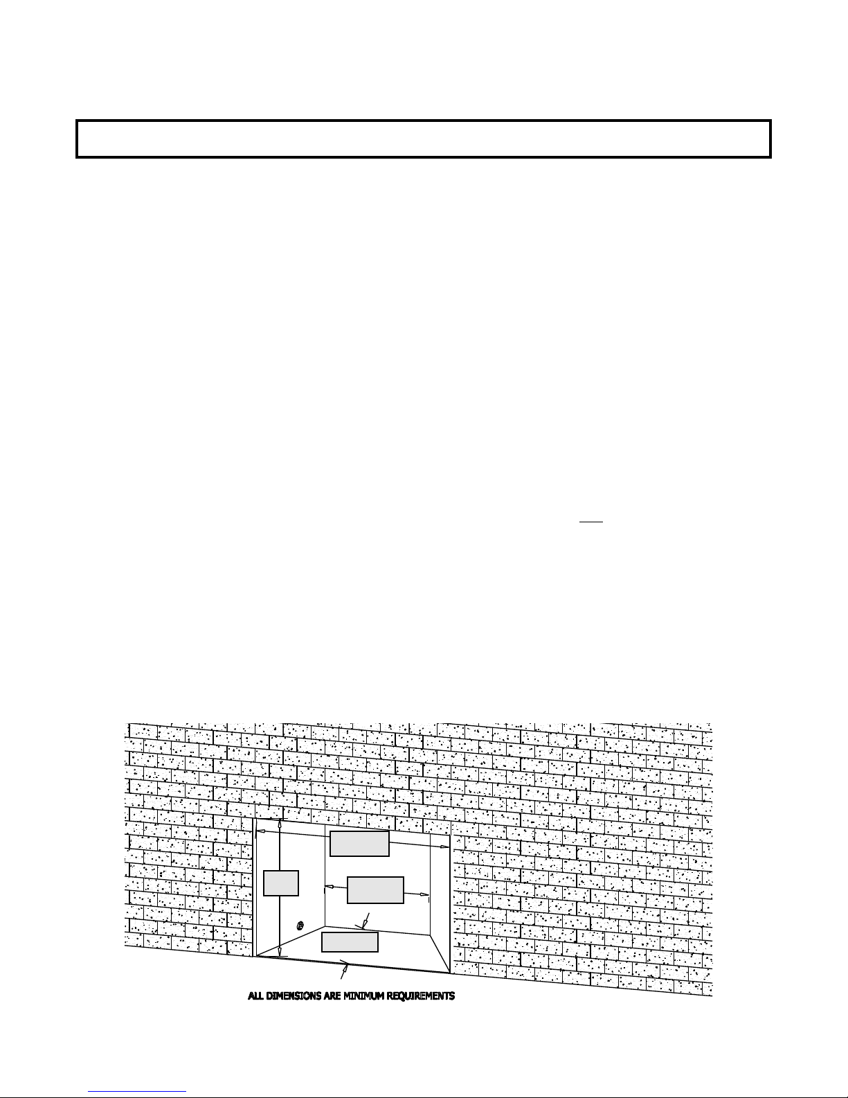
5. The minimum inside dimensions of the existing fireplace must be:
Height: 28” Front Width: 38 1/2”
Depth: 16 1/2” Width at minimum depth location: 26 3/4"
NOTE: The refractory / firebrick may be removed to achieve minimum opening size requirements.
6. Minimum clearance from door frame to side wall: 4 1/2"
Minimum clearance from door frame to a combustible mantel: 16” Mantel depth: 10"
MINIMUM OPENING DIMENSIONS
38 1/2"
28"
26 3/4"
LESS: -24”
16 1/2"
Page 2
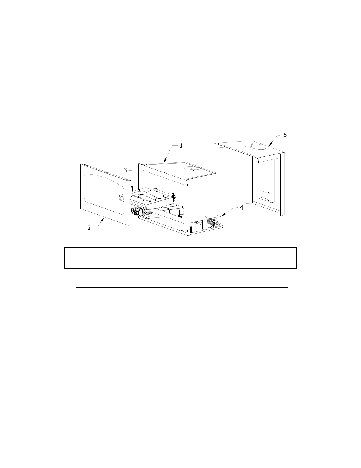
FIREPLACE COMPONENTS:
Check the assembly diagram below to ensure you have all the necessary components to properly install
this fireplace insert.
This insert includes the following:
1. Fireplace Insert.
2. Spring-loaded latch glass assembly.
3. Millivolt board with burner cover.
4. 150 CFM fan with limit switch and speed control.
5. Co-linear air duct.
6. Log set (See page #14).
Figure A
WARNING: Failure to position the parts in accordance with these diagrams or failure to
use only parts specifically approved for this appliance may result in
property damage or personal injury.
Additional components which are necessary for proper installation are:
1. Vent System:
Part #815-CL: For use with minimum 6” x 8” I.D. masonry or 8” I.D. Class ‘A’ metal chimneys - Includes 12 ft.
compressed, expandable to 25 ft. co-linear 3” x 4” flexible chimney, and termination cap. If your existing chimney is higher
than 25 ft. above the fireplace, an extension kit (Part #510) must be used to properly extend the 3” intake and 4” exhaust
up to a maximum of 40 ft.
2. Shroud - 3 pc & 4 pc.: A standard shroud, 48" wide x 32" high is available for this insert and will fit most applications.
Custom shrouds may be ordered on a non-returnable basis. When ordering a custom shroud, please specify the existing
fireplace front opening height and width.
3. Blank Shrouds - 3 & 4 pc. blank shrouds are available for on-site custom fit applications and are sized to the opening
after the insert has been installed. The interior perimeter is properly sized to fit onto the insert. The outer perimeter must
be cut, formed and finished (painted).
4. Upper & Lower Grill set - Several grill set options are available. Contact your dealer for more information.
Page 3

A) PREPARE THE EXISTING FIREPLACE
WARNING: CUTTING ANY SHEET-METAL PARTS OF THE FIREPLACE, IN WHICH THIS GAS
FIREPLACE INSERT IS TO BE INSTALLED, IS PROHIBITED.
1) The refractory, glass doors, screen rails, screen mesh and log grates may be removed from the
fireplace before installing this gas fireplace insert.
2) Any smoke shelves, shields and baffles may be removed if attached by mechanical fasteners.
3) If necessary, remove the firebrick on the sides and back of the existing fireplace to obtain at least the
minimum opening requirements listed on page #2.
4) The fireplace flue damper can be fully blocked open or removed for installation of this gas fireplace
insert.
5) Trim panels or surrounds shall not seal ventilation openings in the fireplace.
6) Remove the existing chimney cap from the chimney.
7) Clean the chimney and inside of the fireplace to prevent creosote smell from entering the home.
8) Place ‘THIS UNIT HAS BEEN MODIFIED’ label in the bottom of the firebox so it will be visible if this
gas fireplace insert is removed.
B. RUN THE GAS LINE
CAUTION: Installation of the gas line must only be done by a qualified person in
accordance with local building codes.
This fireplace insert is equipped with a 3/8" flexible gas line connection 18" long.
CAUTION: The manual shut off valve and millivolt board flexible gas line must not extend outside the insert
cavity. See the WARNING label affixed to the flexible gas line for additional installation instructions
and warnings.
1. Run the gas line into the fireplace, preferably through the side or back, 2” from the bottom of the fireplace.
See Figure B-1 on page #5.
If installing this gas fireplace insert into a factory-built fireplace and the factory-built fireplace has no access
holes(s) provided, an access hole of 1 ½" or less may be drilled through the lower sides or bottom of the
firebox in a proper workmanship like manner. This access hole must be plugged with non-combustible
insulation after the gas supply line has been installed.
A flexible connector should then be attached to the previously run gas line to the point where the manual
shut off valve and millivolt board flexible gas line will connect.
IMPORTANT: An accessible shut off valve (included with this fireplace insert) must be installed up stream from
the regulator.
IMPORTANT: DO NOT RUN THE GAS LINE IN A MANNER THAT WOULD OBSTRUCT THE OPERATION
OF THE FAN OR POSITION OF THE SPEED CONTROL.
Page 4
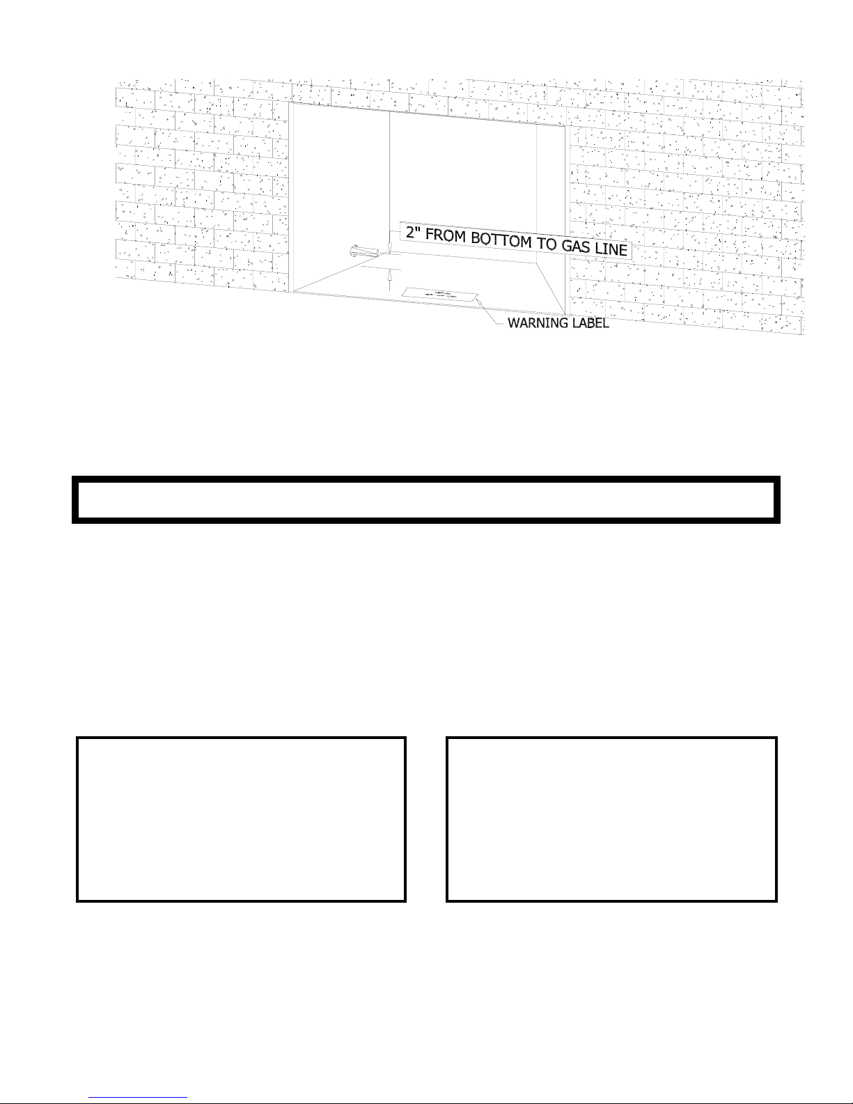
Figure B-1
2. This fireplace insert is designed to accept either a 3/8" or 1/2" gas line approved for gas appliances. Consult
local building codes to properly size the gas supply line leading to a 3/8" reduction.
3. Connect the manual shut off valve to the previous run gas line.
4. The gas line will be connected to the millivolt board later in this manual.
IMPORTANT:
ALL CONNECTIONS WHETHER FIELD OR FACTORY MADE MUST BE CHECKED FOR LEAKS.
NOTE: This appliance and its individual shut off valve must be disconnected from the gas supply piping system
during any pressure testing of that system at test pressures in excess of 1/2 psi.
NOTE: This appliance must be isolated from the gas supply piping system by closing its individual manual shut off
valve during any pressure testing of the gas supply piping sy stems at test pressures equal to or less than1/2
psi.
Pressure check taps for both the manifold (outgoing) and inlet (incoming ) pressures are located in front of the gas
valve. The right pressure tap is the manifold pressure and the left pressure tap is the incoming pressure. Follow
instructions on page #21 for checking these pressures.
NATURAL GAS:
The minimum inlet gas supply pressure: 5.0 in. W.C.
Recommended inlet gas supply pressure: 7.0 in. W.C.
The maximum inlet gas supply pressure: 10.5 in. W.C.
Manifold Pressure: 3.5 in. W.C.
Manifold Pressure (lo setting): 1.7 in. W.C.
Orifice size (0-2000 ft): 30 Input rating: 42,000 BTU/Hr.
Minimum Input rating:
29,500 BTU/Hr.
For high altitude installations, consult the local gas distributor or the authority having jurisdiction for proper rating methods.
Page 5
LP GAS:
The minimum inlet gas supply pressure: 11.0 in. W.C.
Recommended inlet gas supply pressure: 11.0 in. W.C.
The maximum inlet gas supply pressure: 13.0 in. W.C.
Manifold Pressure: 10.0 in. W.C.
Manifold Pressure (lo setting): 6.5 in. W.C.
Orifice size (0-2000 ft): 47 Input rating: 42,000 BTU/Hr.
Minimum Input rating: 30,000 BTU/Hr.

C. REMOVE THE FOLLOWING ITEMS FROM THE FIREPLACE INSERT:
1. GLASS ASSEMBLY: Figure C-1
A) Locate the spring-loaded latches securing the
glass assembly (under the firebox).
B) While holding onto the glass frame, pull the latch
handles out to release from the clips on the glass
assembly.
C) Pull the bottom of the glass assembly out
releasing the tabs at the back of the glass
assembly from the slots in the firebox face, then
lift up off the tabs at the top of the firebox.
D) Set aside where it will not be broken.
E) Remove the log package and bottom refractory
from inside the firebox and set aside for
installation later in this manual.
2. MILLIVOLT BOARD.
A) Loosen and remove the (2) nuts securing the
burner cover. Remove the burner cover by lifting
the front of the cover up, then carefully slide the
burner tube off the orifice. Remove entire assembly
from the firebox. Figure C-2.
1/4" NUTS SECURING BURNER COVER
B) Remove the pilot shield. Figure C-3.
Figure C-2
C) Loosen and remove the (2) 1/4" nuts securing the millivolt board to the firebox bottom. Lift the board
off the studs and remove from the firebox. Figure C-3.
IMPORTANT: BE CAREFUL NOT TO DAMAGE THE GASKET UNDER THE BOARD
Pilot Shield
1/4" NUTS SECURING BURNER
Figure C-3
.
NOTE: The millivolt board is secured with (2) nuts at the factory. After the millivolt board is properly installed it
must be secured with 8 nuts as shown above (6 additional nuts are included in the components packet).
The burner / cover assembly is then placed over the millivolt board and secured with 2 nuts.
Page 6
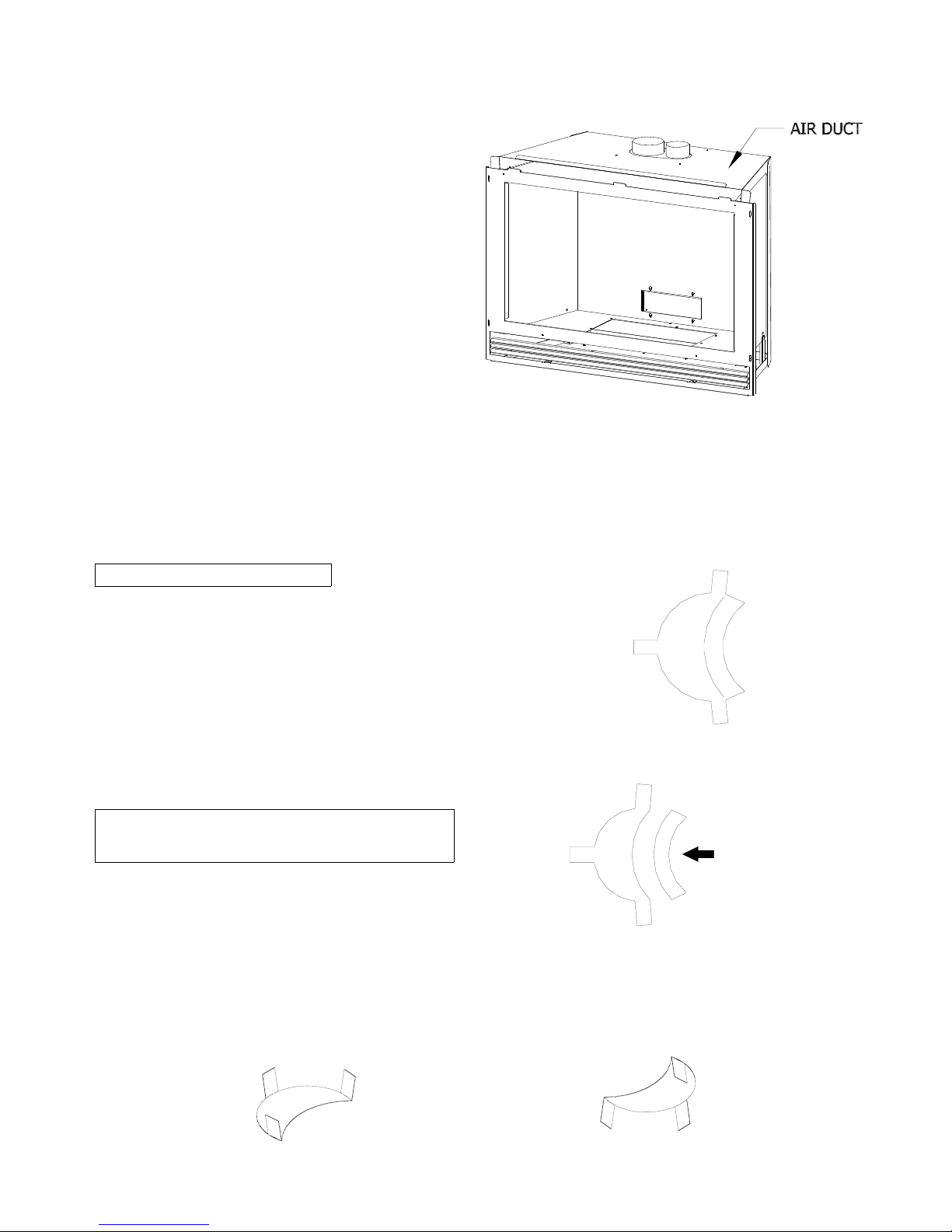
3. REMOVE THE AIR DUCT. Figure C-4.
A. Pull the lower end of the air duct out of the (4)
mounting holes at the back and lift the air duct
(manifold) up from the top of the firebox and
set aside.
Figure C-4
D. INSTALLING THE INSERT
IMPORTANT: ALL STEPS IN SECTION ‘A) PREPARE THE EXISTING FIREPLACE’ MUST BE
COMPLETED BEFORE CONTINUING WITH THIS INSTALLATION.
1. Restrictor Installation
The restrictor plate included in this fireplace
components packet can be installed as either a larg e
or small restrictor, depending on your specific venting
configuration.
There are several factors which can affect proper draft
of the vent system and the burner operation of a
fireplace. Installing a restrictor may be necessary to
resolve the problem, even though it may not be
required under ‘normal conditions’.
IMPORTANT: DO NOT INSTALL IF THE VENTING
CONFIGURATION IS AT THE MINIMUM
REQUIREMENTS!
The restrictor included is sized as the ‘large’ restrictor,
Figure D-1. To reduce the size to the ‘small’ restrictor,
simply bend the section without the tabs off at the
perforation and discard. Figure D-2.
To install the restrictor, refer to Figure D-3 and bend the tabs ‘up’ far enough (approximately 180-degrees) so that
when positioned into the exhaust pipe, will create tension to hold itself in place. Do not over bend the tabs! Slide
the restrictor into the exhaust pipe with the tabs pointing toward you. Access to the exhaust pipe can be gained
by removing the nuts securing the exhaust baffle at the back of the firebox.
Figure D-1
Large Restrictor
Figure D-2
Small Restrictor
Remove this
section.
Figure D-3 Install with the
tabs pointing
TOWARD you.
Page 7
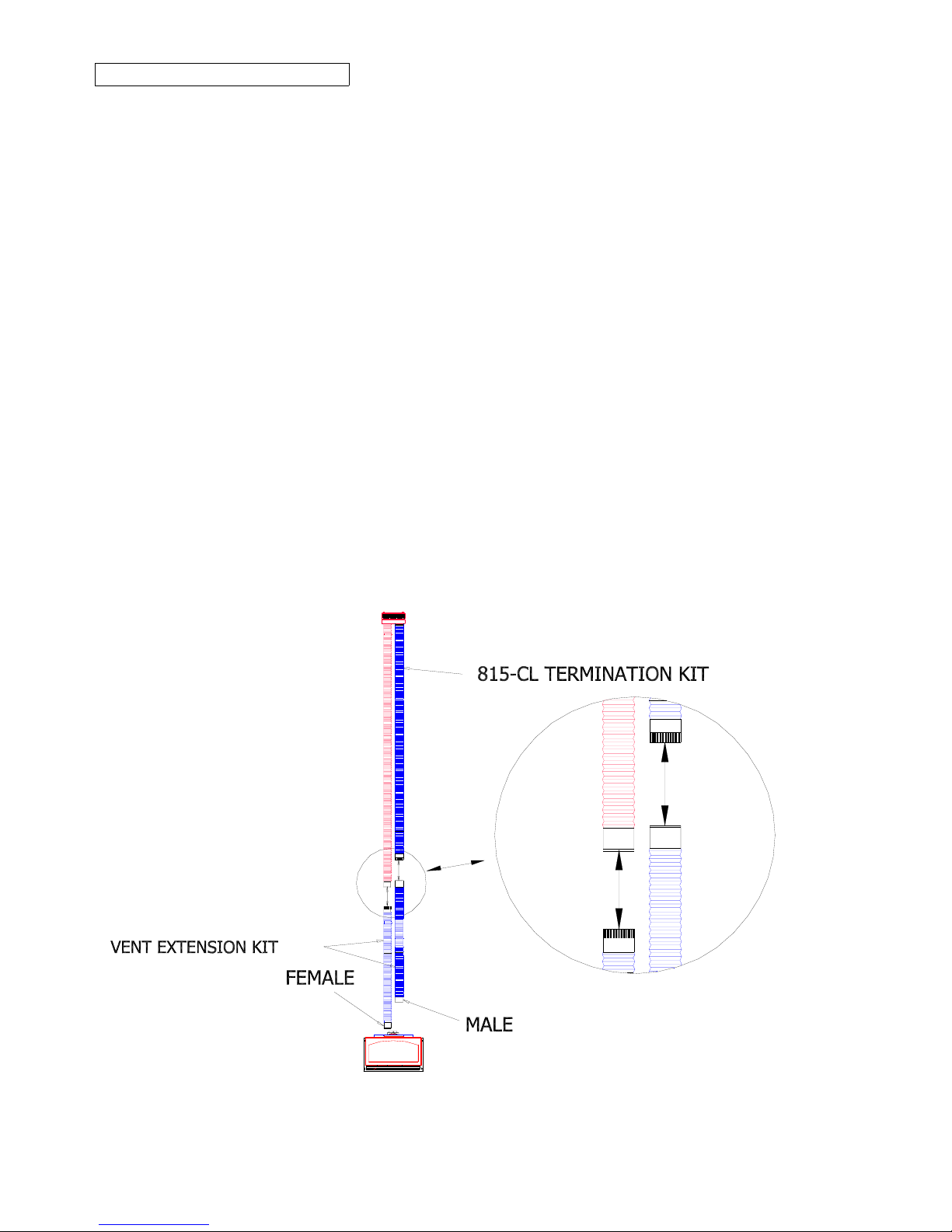
2. INSTALL THE VENT SYSTEM
NOTE: The 4” exhaust pipe and 3” combustion air intake pipe will extend 25 ft. An optional extension kit (Part #510)
is available to extend the #815-CL kit up to a maximum of 40 ft.
A. Carefully extend the 3” combustio n i n t ake an d 4” exh aust p ipes an d exten sion kit (if used )
to equal the total chimney length required.
B. 1. Slide the 3" intake pipe (end without the collar) onto the collar on the termination cap and
secure with 3 self-tapping screws (provided).
2. Place a bead of sealant around th e inner ed ge of the 4" exhaust pipe (end w ithout the
collar) and slide onto the corresponding collar on the termination c ap. Secure with 3 selftapping screws (provided). Apply additional sealant around the joint to ensure a seal.
C. If an extension kit is being used, it must be connected as follows:
Exhaust extension: Apply a liberal bead of sealant (provided) around the exhaust adaptor (male)
extension pipe and slide into the female connector on the end of the 4” exhaust pipe already attached
to the chimney termination plates. Secure with 3 self-tapping screws, (provided). To ensure an airtight seal, additional sealant should be applied at the point of connection.
Combustion intake extension: Apply a liberal bead of sealant (provided) around the male end of
the extension kit and slide into female end of the 3” combustion intake pipe attached to the chimney
termination plates. Secure with 3 self-tapping screws (provided). To ensure an air-tight seal,
additional sealant should be applied at the point of connection.
FIGURE D-4
Page 8
 Loading...