

kozy heat 911, 911-IPI, 911-RAD, 911-MV Installation Manual
I N S T A L L A T I O N M A N U A L
DIRECT VENT FIREPLACE INSERT
IMPORTANT: This installation manual is to be used in conjunction with SUPPLEMENTAL
INSTALLATION AND HOMEOWNER INFORMATION MANUAL. Read both manuals before installing
and operating appliance.
INSTALLER: Leave this manual with the appliance.
CONSUMER: Retain this manual for future reference.
This applianc e may be inst alled in an af ter mar ket pe rma nently locat ed,
manufactured home (USA only) or mobile home, where not prohibited by local codes.
This appliance is only for use with the type of gas indicated on the rating plate. This
appliance is not convertible for use with other gases, unless a certified kit is used.
WARNING: If the information in these instructions is not followed exactly, a fire
or explosion may result causing property damage, personal injury or loss of life.
—Do not store or use gasoline or other flammable vapors and liquids in the vicinity
of this or any other appliance.
WHAT TO DO IF YOU SMELL GAS:
◙ Do not try to light any appliance.
◙ Do not touch any electrical switch: do not use any phone in your building.
◙ Immediately call gas supplier from a neighbors phone. Follow the gas supplier
instructions.
◙ If you cannot reach your gas supplier, call the fire department.
— Installation and service must be performed by a qualified installer, service
agency or the gas supplier.
English and French Installation Manuals
Available Through Your Local Dealer or
Visit Our Website at www.kozyheat.com
WARNING
HOT GLASS WILL CAUSE BURNS.
DO NOT TOUCH GLASS UNTIL COOLED.
NEVER ALLOW CHILDREN TO TOUCH GLASS.
Report Number: 216-F-22b-6.5
JUNE 2012
911-R19
www.kozyheat.com
INTRODUCTION
Read this manual before installing or operating this appliance.
Please retain this owner’s manual for future reference.
CONGRATULATIONS!
We welcome you as a new owner of a Kozy Heat gas fireplace. Kozy Heat products are
designed with superior components and materials and assembled by trained craftsmen who
take pride in their work. The burner and valve assembly are 100% test-fired and the complete
fireplace is thoroughly inspected before packaging to ensure that you receive a quality product.
Our commitment to quality and customer satisfaction have remained the same for over 30
years. We offer a complete line of gas and wood fireplaces, unique cabinets and stylish
accessories to compliment any décor. Adding a fireplace is one of the best ways to increase the
value of your home and we are proud to offer a network of dealers throughout the country to
help make your experience everything you imagine. We pride ourselves in being dedicated to
not only function and reliability, but customer safety as well. We offer our continual support
and guidance to help you achieve the maximum benefit and enjoyment from your Kozy Heat
gas fireplace.
Jim Hussong Dudley Hussong
President Board Chairman
Homeowner Reference Information
We recommend that you record the following information about your fireplace.
Model Name:_________________________________ Date purchased/installed:__________________________________
Serial Number:________________________________ Location on fireplace:____________________________________
Dealership purchased from:______________________ Dealer Phone:___________________________________________
Notes:_______________________________________________________________________________________________
____________________________________________________________________________________________________
____________________________________________________________________________________________________
1

TABLE OF CONTENTS
INTRODUCTION
Introduction and Homeowner Reference Information 1
TABLE OF CONTENTS
Table of Contents 2
SAFETY INFORMATION
Safety Information 3
COMMONWEALTH OF MASSACHUSETTS INFORMATION
Commonwealth of Massachusetts Information 4
SPECIFICATIONS
Fireplace Insert Dimensions 5
Clearances 5
Additional Components Required 6
Placement Clearance Requirements 6
EXISTING FIREPLACE SPECIFICATIONS
Existing Fireplace Requirements 7
Existing Fireplace Minimum Opening Requirements 7
PREPARE EXISTING FIREPLACE
Prepare Existing Fireplace 7
GLASS FRAME ASSEMBLY
Remove Glass Frame Assembly 7
Install Glass Frame Assembly 7
ELECTRICAL WIRING
Electrical Wiring 7
GAS LINE CONNECTION
Gas Line Connection 8
INSTALLATION
Approved Venting 9
Air Duct Removal 9
911-MSP Masonry Side Panel Installation (Optional) 9
Restrictor 9
VENTING INSTALLATION
Kozy Heat #815-CL Co-Linear Vent System 10-11
Kozy Heat #815-CA Co-Axial Vent System 12-13
CONTROL BOARD
Control Board Installation 14
Control Board Removal 14
ZC SHROUD ASSEMBLY AND INSTALLATION
ZC Shroud Assembly and Installation 15
MASONRY SHROUD ASSEMBLY AND INSTALLATION
Masonry Shroud Assembly and Installation 16-17
LOG SET INSTALLATION
Log Set Installation 18
FINALIZING THE INSTALLATION
Flame Appearance 19
Venturi Adjustment 19
Restrictor Usage / Troubleshooting / Installation / Modification 20
Seasonal Heat Dump 21
MAINTENANCE
Maintenance 22
WARRANTY
Warranty 23-24
2

SAFETY INFORMATION
This fireplace has been tested by OMNI-Test Laboratories, Portland, Oregon and complies with:
ANSI Z21.88-2009 “Standard for Vented Gas Fireplace Heaters.”
This installation must conform with local codes, or in the absence of local codes, with the National Fuel Gas Code, ANSI Z223.1/NFPA 54.
Installation and repair should be done only by a qualified service person. The appliance should be inspected by a
qualified service person before use. Annual inspection by a qualified service person is required to maintain warranty.
More frequent cleaning may be required due to excessive lint from carpeting, bedding materials, etc. It is imperative
th a t con trol co mpa r t m e n t s, burners a n d c i rc ulation air p a s sag eways of the a p p l ia nce be kept c l ea n.
This fireplace insert is to be installed into a solid fuel masonry or factory built non-combustible fireplace that has been
i n s t a ll ed i n a c c o r d a nc e w i t h t he N at i o n a l , P ro vi nc ia l, S ta te a n d l o c al b ui ld in g c o d es .
Children and adults should be alerted to the hazards of high surface temperatures and should stay away to avoid burns
or clothing ignition.
Young children should be carefully supervised when they are in the same room as the appliance. Toddlers, young
children and others may be susceptible to accidental contact burns. A physical barrier is recommended if there are at
risk individuals in the house. To restrict access to a fireplace or stove, install an adjustable safety gate to keep toddlers ,
young children and other at risk individuals out of the room and away from hot surfaces.
Clothing or other flammable material should not be placed on or near the appliance.
Adequate accessibility clearances for servicing and proper operation must be maintained.
This appliance must not share or be connected to a chimney flue serving any other appliance.
Keep area around the appliance clear of combustible materials, gasoline and other flammable vapor and liquids.
The flow of combustion and ventilation air must not be obstructed.
Due to high temperatures the appliance should be located out of traffic and away from furniture and draperies.
The glass front or any part removed for servicing the appliance must be replaced prior to operating the appliance.
Work should be done by a qualified service technician.
Clean glass only when cool and only with non-abrasive cleansers.
WARNING: DO NOT OPERATE APPLIANCE WITH THE GLASS/FRAME ASSEMBLY REMOVED, CRACKED
OR BROKEN. REPLACEMENT OF THE GLASS SHOULD ONLY BE PERFORMED BY A LICENSED OR
QUALIFIED SERVICE PERSON.
The glass assembly, Part #700-08T, shall only be replaced as a complete unit, as supplied by Hussong Mfg. Co., Inc.
DO NOT SUBSTITUTE MATERIALS.
Do not strike or slam glass assembly.
Any safety screen or guard removed for servicing the appliance must be replaced prior to operating the appliance.
Under no circumstances should any solid fuel (wood, coal, paper or cardboard etc.) be used in this appliance.
Keep burner and control compartment clean.
Do not use this fireplace if any part has been under water. Immediately call a qualified service technician to inspect this
appliance and to replace any part of the control system and any gas control which has been under water.
3

COMMONWEALTH OF MASSACHUSETTS REQUIREMENTS
NOTE The following requirements reference various Massachusetts and national codes not contained in this manual.
For all sidewall horizontally vented gas fueled equipment installed in every dwelling, building or structure used in whole or in part for residential purposes,
including those owned or operated by the Commonwealth and where the side wall exhaust vent termination is less than (7) feet above finished grade in the
area of the venting, including but not limited to decks and porches, the following requirements shall be satisfied:
INSTALLATION OF CARBON MONOXIDE DETECTORS
At time of installation of side wall horizontally vented gas fueled equipment, the installing plumber or gas -fitter shall observe that a hard wired carbon
monoxide detector with an alarm and battery back-up is installed on the floor level where the gas equipment is to be installed. In addition, the installing
plumber or gas-fitter shall observe that a battery operated or hard wired carbon monoxide detector is installed on each additional level of the dwelling,
building or structure served by the side wall horizontal vented gas fueled equipment. It shall be the responsibility of the property owner to secure the services
of qualified licensed professionals for the installation of hard wired carbon monoxide detectors .
In the event that the side wall horizontally vented gas fueled equipment is installed in a crawl space or attic, the hard wir ed carbon monoxide detector with
alarm and battery back-up may be installed on the next adjacent floor level.
In the event that the requirements of this subdivision can not be met at the time of completion of installation, the owner shall have a period of thirty (30) days
to comply with the above requirements; provided, however, that during said thirty (30) day period, a battery operated carbon monoxide detector with an
alarm shall be installed.
APPROVED CARBON MONOXIDE DETECTORS
Each carbon monoxide detector as required in accordance with the above provisions shall comply with NFPA 720 and be ANSI/UL 2 034 listed and IAS
certified.
SIGNAGE
A metal or plastic identification plate shall be permanently mounted to the exterior of the building at a minimum of eight (8 ) feet above grade directly in line
with the exhaust vent terminal for the horizontally vented gas fueled heating appliance or equipment. The sign shall read, in print no less the one-half inch
(1/2) in size, “GAS VENT DIRECTLY BELOW. KEEP CLEAR OF ALL OBSTRUCTIONS”.
INSPECTION
The state or local gas inspector of the side wall horizontally vented gas fueled equipment shall not approve the installation unless, upon inspection, the
inspector observes carbon monoxide detectors and signage installed in accordance with the provisions of 248 CMR 5.08 (2) (a) 1 through 4.
EXEMPTIONS
The following equipment is exempt from 248 CMR 5.08 (2) (a) 1 through 4:The equipment listed in Chapter 10 entitled “Equipment Not Required To Be
Vented” in the most current edition of NFPA 54 as adopted by the Board; and Product Approved side wall horizontally vented gas fueled equipment installed
in a room or structure separate from the dwelling, building or structure used in whole or in part for residential purposes.
MANUFACTURER REQUIREMENTS - GAS EQUIPMENT VENTING SYSTEM PROVIDED
When the manufacturer of Product Approved side wall horizontally vented gas equipment provides a venting system design or venting system components
with the equipment, the instructions provided by the manufacturer for installation of the equipment and the venting system shall include:
Detailed instructions for the installation of the venting system design or the venting system components; and
A complete parts list for the venting system design or venting system.
MANUFACTURER REQUIREMENTS - GAS EQUIPMENT VENTING SYSTEM NOT PROVIDED
When the manufacturer of Product Approved side wall horizontally vented gas equipment does not provide the parts for venting the flue gases, but identifies
“special venting systems”, the following requirements shall be satisfied by the manufacturer:
The referenced “special venting systems” instructions shall be included with the appliance or equipment installation instructions and;
The “special venting systems” shall be Product Approved by the Board, and the instructions for that system shall include a parts list and detailed
installation instructions.
A copy of all installation instructions for all Product Approved side wall horizontally vented gas fueled equipment, all vent ing instructions, all parts lists for
venting instructions, and/or all venting design instructions shall remain with the appliance or equipment at the completi on o f the installation.
4
SPECIFICATIONS
31
1
4
"
794mm
18"
457mm
19
1
2
"
495mm
2
1
4
"
57mm
14
1
2
"
368mm
29
1
2
"
749mm
4
3
4
"
121mm
16
1
8
"
410mm
20
7
8
"
530mm
TOP
FRONT
RIGHT
LEFT
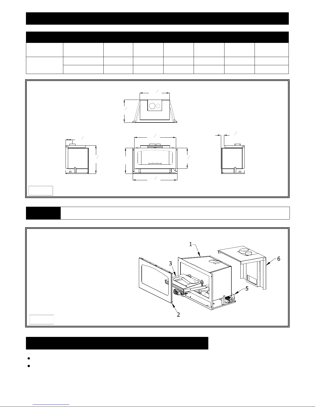
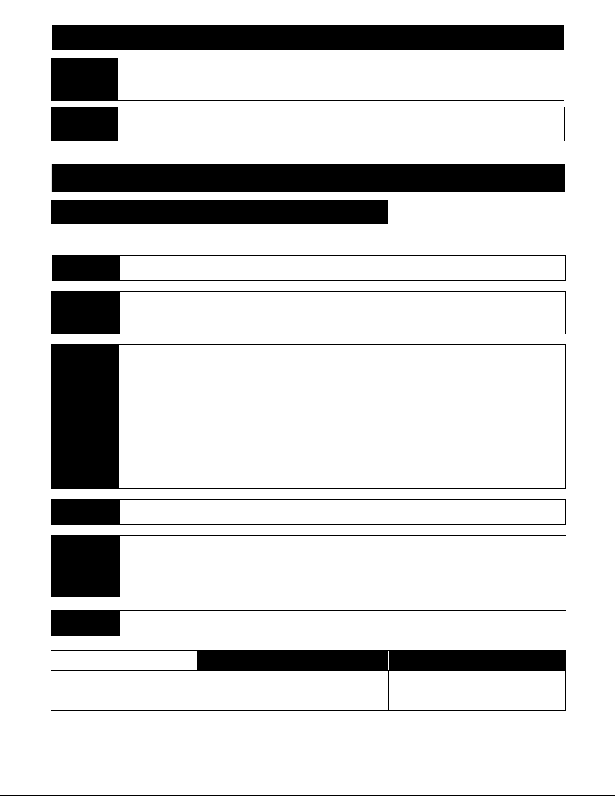
FIREPLACE DIMENSIONS
DESCRIPTION Height Width Back Width Depth Back Height Back to Vent Center
FIREPLACE
DIMENSIONS
Figure 5a
INCHES 18 31-1/4 20-7/8 16- 1/8 19-1/2 4-3/4
MILLIMETERS 457 794 530 410 495 121
WARNING
Failure to position components in accordance with these diagrams or failure to use only parts specifically approved for use with
911 may result in property damage or personal injury.
1. Fireplace insert
2. Spring-loaded latch glass frame assembly
3. Control board with burner cover
4. Log set (see page 18)
5. *150 CFM fan kit
6. Co-linear air duct
*Optional accessory for 911-RAD models.
Figure 5b
MINIMUM CLEARANCES TO COMBUSTIBLES
Insert glass to sidewall: 10” (254 mm)
Insert top to combustible 10” (254mm) mantel: 12” (305 mm)
5

SPECIFICATIONS
ADDITIONAL COMPONENTS REQUIRED
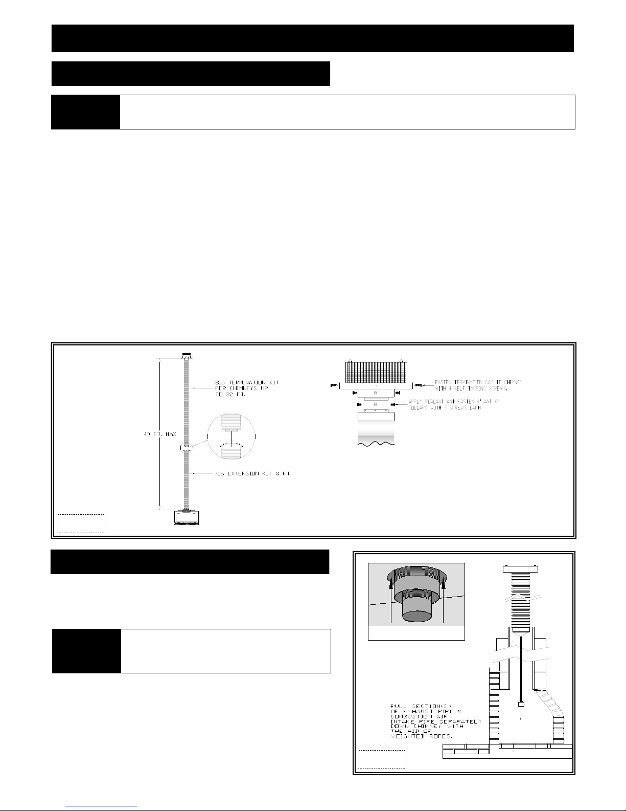
Vent System; Part #815-CL: For use with minimum 6” x 8” I.D. masonry or 8” I.D. Class A metal chimneys - Includes 12 ft. (3.66 m)
Part #510 : Used in conjunction with #815-CL to extend termination up to a maximum of 30 ft. (9.14 m).
Part #815-CA: For use with minimum 7” I.D. Class ‘A’ metal chimneys - Includes 12 ft. (3.66 m) compressed expandable
Part #716A: Used in conjunction with #815-CA to ext end termination up to a maximum of 40ft. (12.19 m).
Other approved venting: Selkirk, ICC, American Metals, Security
Shrouds - 3 pc & 4 pc.: Standard shrouds are available for this insert and will fit most applications. Custom shrouds may be ordered on a
Blank Shrouds - 3 & 4 pc.: Blank shrouds are available for on-site custom fit applications and are sized to the opening after the insert has
been installed. The interior perimeter is properly sized to fit onto the insert. The outer perimeter must be cut,
formed and finished (painted). Grill set or clean face frame (required) in various finishes purchased separately.
Full Door Shrouds: Full door decorative shrouds are available for this insert and are used in place of a standard or blank shroud.
PLACEMENT CLEARANCE REQUIREMENTS
This fireplace must be installed on a level surface capable of supporting the fireplace and venting.
This fireplace insert is to be installed into a solid fuel masonry or factory built non-combustible fireplace that has been installed in
accordance with the National, Provincial, State and local building codes.
Due to high surface temperatures, fireplace should be located out of traffic and away from furniture and draperies.
This fireplace may be installed in a bedroom.
Please be aware of the large amount of heat this fireplace will produce when determining a location.
compressed, expandable to 25 ft (7.62 m) co-linear 3” x 4” flexible chimney, and termination cap.
to 32 ft. (9.75 m) co-axial 4” x 6” flexible chimney system, co-axial air duct, and termination cap.
non-returnable basis. When ordering a custom shroud, please specify existing fireplace front opening height and
wid t h . G r i ll s et o r cl e a n f a c e f r am e ( re q u ir e d ) i n va r i ou s fin i sh e s pu r ch a s ed s e pa r at e l y.
Or
Or
EXISTING FIREPLACE SPECIFICATIONS
EXISTING FIREPLACE REQUIREMENTS
THIS INSERT IS APPROVED FOR INSTALLATION IN MASONRY AND FACTORY-BUILT SOLID FUEL BURNING FIREPLACES.
The existing fireplace & chimney must be clean and in good working order and constructed of non-combustible materials.
A gas line must be able to be installed to insert.
Provisions made to provide electrical power to operate insert fan and thermostatic control (if used).
Any chimney clean-outs must fit properly.
Existing Chimney must be comprised of one of the following: Factory built chimney: Co-linear - 8” (203 mm) minimum inside diameter.
Co-axial - 7” (178 mm) minimum inside diameter.
Masonry Chimney: 6" x 8" minimum inside diameter.
Existing Chimney Height: Minimum: 12 ft. (3.66 m)
Maximum: Co-axial venting: 40 ft. (12.19 m)
Co-linear venting: 30 ft. (9.14 m)
DETERMINE LENGTH OF EXISTING CHIMNEY
1. Remove and discard existing chimney cap.
NOTE It is helpful to have two people complete next step to determine chimney height.
2. Position one person at fireplace and another person at top of chimney.
Measure from fireplace base to top of chimney.
Subtract 24” (610mm) (height of insert).
This is the total length of co-linear flexible aluminum you will require.
MEASUREMENT FROM FIREPLACE BASE TO TOP OF CHIMNEY:_________________
LESS 24" (610mm) (HEIGHT OF INSERT): -24" (610mm)____
TOTAL CHIMNEY LENGTH REQUIRED: _________________
CAUTION
This appliance must not be connected to or joined with any other chimney flue
serving another appliance.
6
EXISTING FIREPLACE SPECIFICATIONS
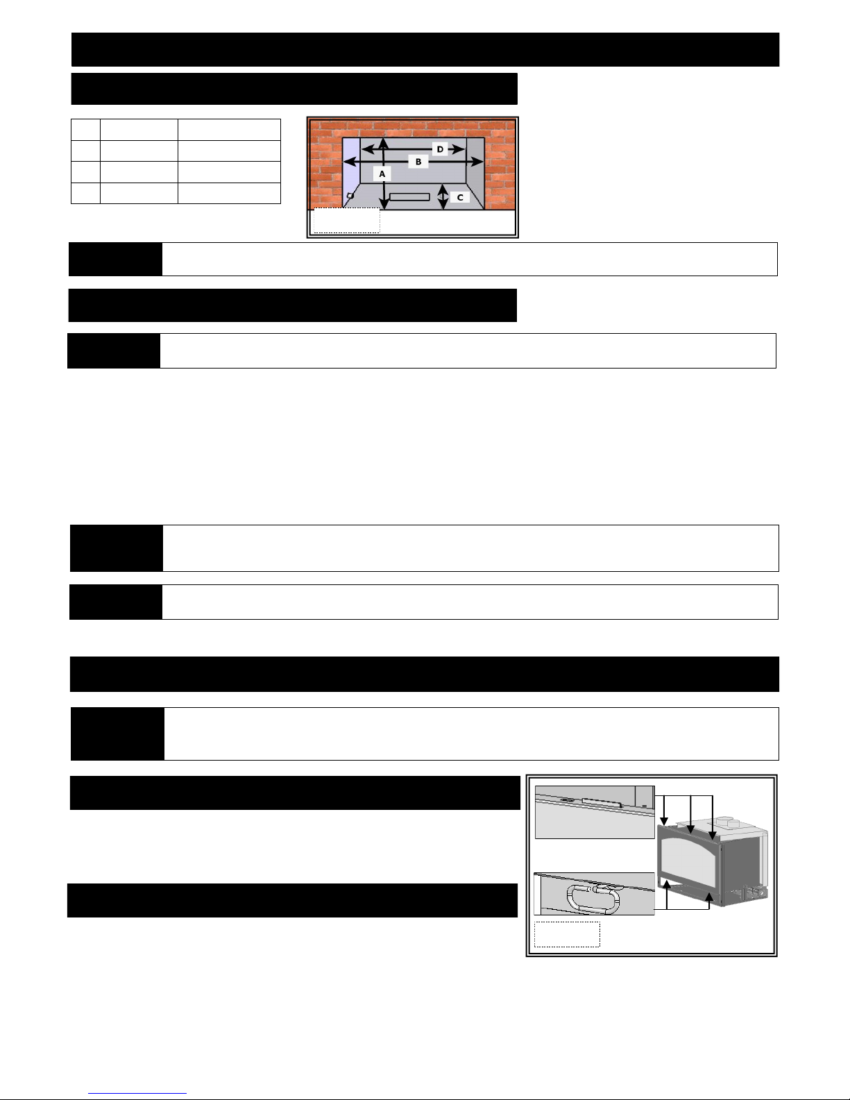
EXISTING FIREPLACE MINIMUM OPENING REQUIREMENTS
A Height 19” (483mm)
B Front Width 31-1/2” (770mm)
C Depth 16-1/4” (413mm)
D Back Width 21” (533mm)
All dimensions are minimum requirements
OPTIONAL
Masonry panel kit #911-MSP is available and can be installed on this insert when installed in an existing masonry opening
that is larger than the insert. Its purpose is to concentrate flow of heated room air between the firebox and panel walls.
Figure 7a
PREPARE EXISTING FIREPLACE
ATTENTION Any removed parts must be capable of reinstallation if this insert is ever removed (removal of rivets or screws is acceptable).
Any removed parts must be capable of reinstallation if this insert is ever removed (removal of rivets or screws is acceptable ).
The refractory, glass doors, screen rails, screen mesh and log grates may be removed from existing fireplace before installing this gas
fireplace insert. Any smoke shelves, shields and baffles may be removed if attached by mechanical fasteners. If necessary, remove firebrick
to obtain at least minimum opening requirements.
The fireplace flue damper can be fully blocked open or removed for installation of this gas fireplace insert. Remove existing chimney cap.
Clean chimney and inside of fireplace to prevent creosote smell from entering the home.
Cutting of any sheet metal parts is prohibited, except the metal floor. If metal floor is removed, the insert must be placed directly on metal
base of metal fireplace.
Mechanically attach ‘THIS UNIT HAS BEEN MODIFIED’ label at bottom of existing firebox so it will be visible if this gas fireplace
insert is removed.
IMPORTANT
CAUTION Tri m panel s or surrounds must not seal ventilation openings in existing fireplace that this appliance is installed in.
If the factory-built fireplace has no gas access hole(s) provided, an access hole of 1 -1/2” (37.5 mm) or less may be drilled
through the lower sides or bottom of the firebox in a proper workmanship like manner. The access hole must be plugged with
non-combustible insulation after the gas supply line has been installed.
GLASS FRAME ASSEMBLY
DO NOT OPERATE THIS FIREPLACE WITH GLASS REMOVED, CRACKED OR BROKEN. REPLACEMENT OF GLASS ASSEMBLY,
WARNING
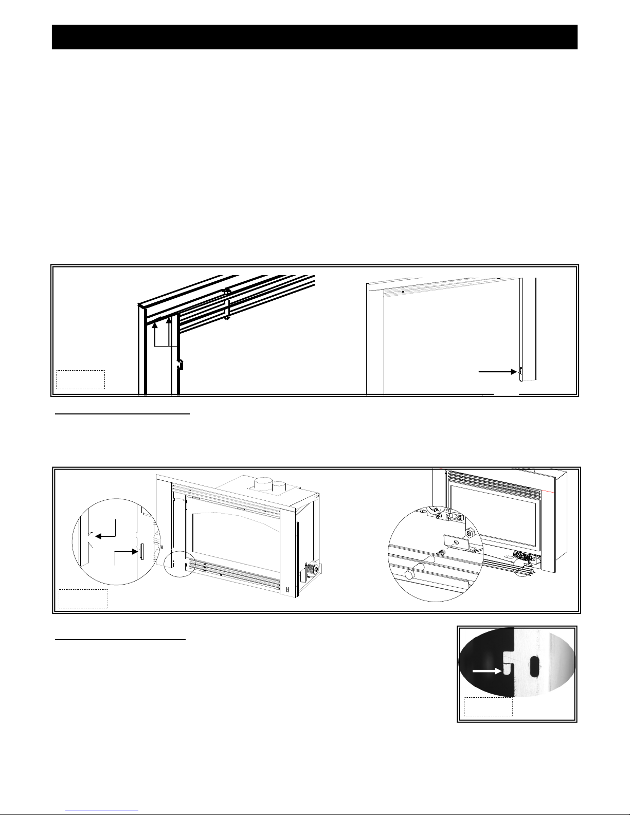
REMOVE GLASS FRAME ASSEMBLY
1. Locate spring-loaded handles securing glass frame assembly at bottom of firebox.
2. Pull bottom handles out and down to release glass frame assembly bottom.
3. Pull bottom of glass frame assembly out and lift up off tabs at top of firebox.
INSTALL GLASS FRAME ASSEMBLY
A. Pl ac e g la ss f ra me a s s em bl y t o p o v er t a bs a t t o p o f f ir eb ox .
B. Pull botto m handles out and up to secure glass frame assembly bottom.
#700-08T SHOULD BE DONE BY A LICENSED OR QUALIFIED SERVICE PERSON.
DO NOT REMOVE GLASS ASSEMBLY WHEN HOT!
7
Figure 7b
ATTENTION
ELECTRICAL WIRING
Electrical wiring must be installed by a licensed electrician.
This appliance must be electrically wired and grounded in accordance with local codes or, in the absence of local codes, with
Nation Electric Code, ANSI/NFPA 70-latest edition, or the Canadian Electric Code, CSA C22.1
WARNING
This appliance is equipped with a three-prong (grounding) plug for protection against shock hazard and should be plugged
directly into a proper ly grou nded three-prong receptacle. Do not cut or remove gro unding prong from thi s plug.
Do not allow excess cord to touch fireplace.
GAS LINE CONNECTION
GAS CONVERSION
This fireplace is manufactured for use with Natural Gas. Follow instructions included with conversion kit if converting to LP gas.
ATTENTION
CAUTION
NOTE
The conversion shall be carried out in accordance with the requirements of the provincial authorities having jurisdiction and in
accordance with the requirements of the ANSI Z223.1 installation code.
Installation of the gas line must only be done by a qualified person in accordance with local building codes, if any.
If not, follow ANSI 223.1.
Commonwealth of Massachusetts: Installation must be done by a licensed plumber of gas fitter.
A listed (and Commonwealth of Massachusetts approved) 1/2” (13mm) T-handle manual shut-off valve and flexible gas
connector (included) are connected to the 1/2” (13mm) control valve inlet. If substituting for these components, please consult
local codes for compliance.
This fireplace is equipped with a 3/8”(10mm) x 18” (457mm) long flexible gas connector and manual shut-off valve. The gas
line should be run to the point of connection where the shut-off valve and flexible gas line will connect.
The appliance and its individual shutoff valve must be disconnected from the gas supply piping system during any pressure
testing of that system at pressures in excess of ½ psi (3.5 kPa).
The appliance must be isolated from the gas supply piping system by closing its individual manual shut-off valve during any
pressure testing of the gas line at test pressures equal to or less than ½ psi (3.5 kPa).
For high altitude installations, consult the local gas distributor or the authority having jurisdiction for proper rating methods.
IMPORTANT
NOTE
IMPORTANT Do not run gas line in a manner that would obstruct fan operation.
NATURAL GAS LP GAS
MINIMUM INLET GAS PRESSURE 5” WC (1.25 kPa) (7” WC (1.74 kPa) (recommended) 11” WC (2.74 kPa) (recommended)
MAXIMUM INLET GAS PRESSURE 10.5” WC (2.62 kPa) 13” WC (3.24 kPa)
The efficiency rating of this appliance is a product of thermal efficiency rating determined under continuous operating
conditions and was determined independently of any installed system.
If installing this insert into minimum opening dimensions, the gas line may need to be run after placement due to space
limitations.
If installing this gas fireplace insert into a factory-built fireplace and the factory-built fireplace has no access hole provided, an
access hole of 1 ½"(38 mm) or less may be drilled through the lower sides or bottom of the firebox in a proper workmanship like
manner. This access hole must be plugged with non-combustible insulation after the gas supply line has been installed.
8
INSTALLATION
ATTENTION All steps as outlined in ‘PREPARE EXISTING FIREPLACE’ must be completed before continuing with this installation.
APPROVED VENTING
Kozy Heat #815-CL Co-Linear Vent System. Follow instructions on pages 10-11.
Kozy Heat #815-CA Co-Axial Vent System. Follow instructions on pages 12-13.
Selkirk, ICC, American Metals, Security. Follow instructions included from vent pipe manufacturer as well as venting requirements as
outlined in this installation manual.
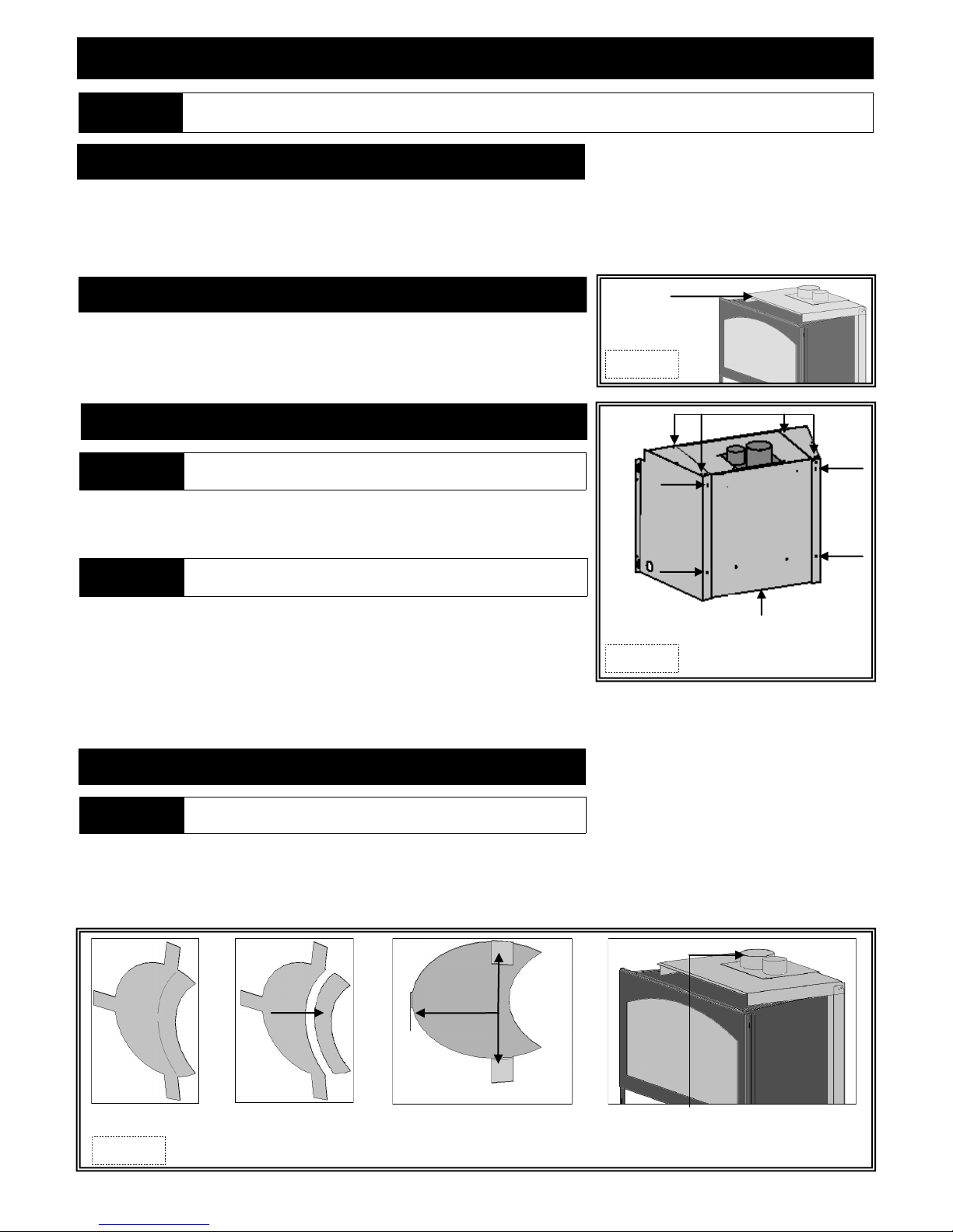
AIR DUCT REMOVAL
Remove air duct by lifting up and off top of insert. Follow instructions below and on
following pages for vent system attachment to air duct.
#911-MSP MASONRY SIDE PANEL INSTALLATION (OPTIONAL)
IMPORTANT
This kit includes: (1) Right side panel
(1) Left side panel
(12) Sheet metal screws
NOTE
1. If air duct on insert is not positioned outside flange at bottom, remove and
reposition.
2. Position each side panel outside the flanges on insert bottom, aligning (2) holes in
top and (2) holes in back of masonry side panels with corresponding holes in air
duct. Secure with screws included.
This installation will be continued at a later point.
For use when insert is installed in an existing masonry opening. This kit
must be attached to air duct (manifold) prior to vent system connection.
If air duct and masonry side panels are not placed outside flanges at
insert bottom, a rattling noise may occur when fan is in operation.
Air Duct
Figure 9a
Figure 9b
Maso nry side pane ls and air du ct po sit ioned
outside flange at bottom of insert.
RESTRICTOR INSTALLATION
IMPORTANT Do not install if venting configuration is at minimum requirements.
Each installation is unique and affected by various factors including venting configuration, altitude and climate. Therefore, after fireplace
insert installation is complete, a restrictor may be required or may need to be removed or modified.
Page 20 has information on restrictor recommendations depending on burner flame appearance and instructions on installation after ven ting
is completed.
Large Restrictor Re mo v e t a b ( s ) t o
create small restrictor
Figure 9c
Be nd tabs t o a ppr ox. 80 d egr e e
an gl e s to cr eate t ens ion to h ol d
itse l f i n p l a c e wh e n i nsta ll e d.
9
Slide restrictor into exhaust pipe on top of fireplace
with tabs pointing towards you prior to attaching
venting.
VENTING INSTALLATION
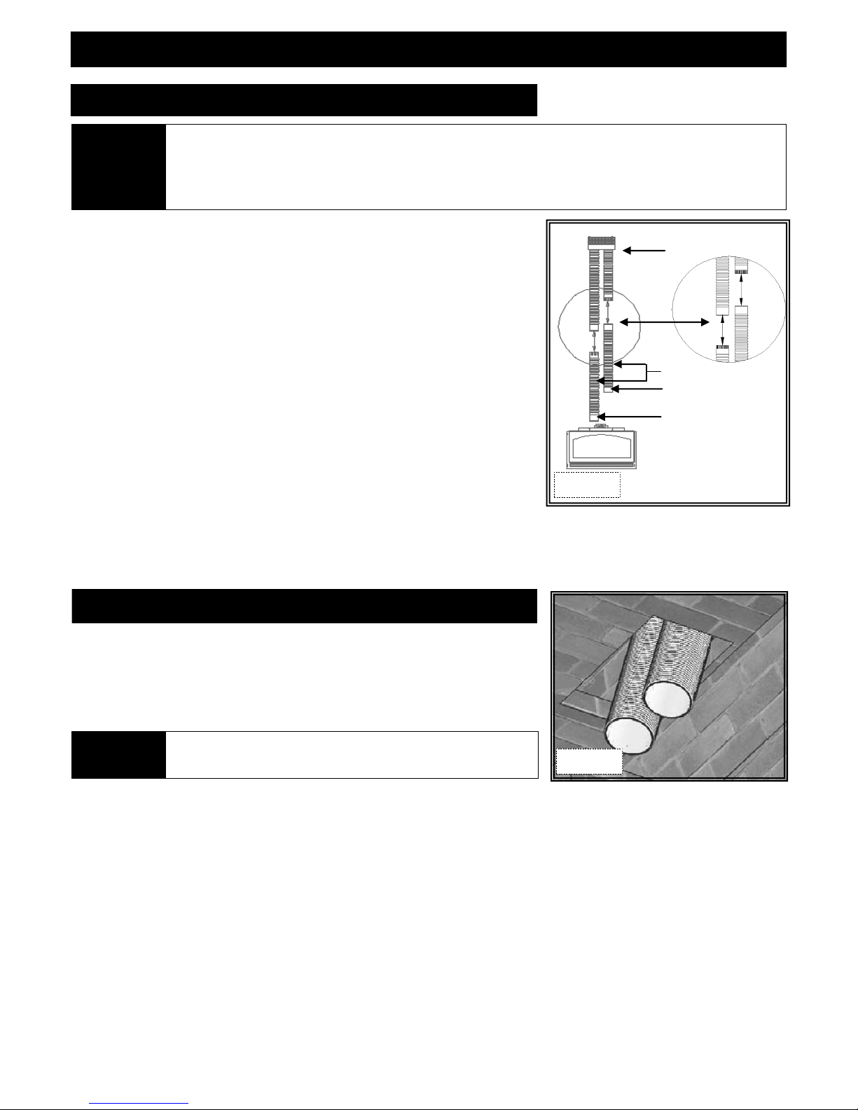
KOZY HEAT #815-CL CO-LINEAR VENT SYSTEM
The co-linear pipe included with this vent system is designed to extend up to 25 ft. (7.62 m). If additional length is required, Part
#510 is available to extend venting to a maximum of 30 ft . (9.14 m).
NOTE
A. Carefully extend 3” combustion intake and 4” exhaust pipes (and extension kit if
used) to equal total chimney length required.
Full Connection method:
Slide 3" intake pipe (end without collar) over collar on termination cap. Secure
with 3 self-tapping screws (provided).
B. Place bead of sealant around inner edge of exhaust pipe (end without collar) and slide
onto corresponding collar on termination cap. Secure with 3 self-tapping screws
(provided). Apply additional sealant around joint to ensure a seal.
C. If an extension kit is being used, it must be connected as follows:
Exhaust extension:
Apply a liberal bead of sealant around exhaust adaptor (male) extension pipe and
slide into female connector on end of 4” exhaust pipe already attached to the chimney
termination plates. Secure with 3 self-tapping screws, (provided). To ensure an
air-tight seal, additional sealant should be applied at the point of connection.
Combustion intake extension:
Apply a liberal bead of sealant (provided) around male end of extension kit and slide
in t o f em a le e nd of 3 ” c o mb u st i on in ta k e p ip e a t ta c he d t o c h im n ey
termination plates. Secure with 3 self-tapping screws (provided). To ensure an
air-t ight seal, ad dit ion al sealant should be applied at point of co nnection.
If using ‘stub’ method for combustion air pipe, extending it is not necessary. Determine length needed from insert air duct
(4 ft. (1.22 m) minimum) to above damper opening in existing chimney. Remove excess combustion air pipe from end without
collar. Continue with Step B. #2 below.
#815-CL Termination Kit
Vent Extension Kit
Male
Female
Figure 10a
RUN VENTING THROUGH EXISTING CHIMNEY
We strongly suggest wrapping first 3ft. (914mm) of vent system below termination cap
with non-faced fiberglass insulation (secure with wire) before running it through existing
chimney. This will prevent cold air from coming down existing chimney.
DO NOT USE THIS METHOD IF YOU ARE STUBBING COMBUSTION AIR
PIPE FROM BOTTOM OF EXISTING CHIMNEY.
NOTE
If offsets are present in existing chimney, place a weighted rope around
pipe ends to guide them through chimney.
DO NOT ATTEMPT TO TIE ONE ROPE AROUND BOTH PIPES.
Figure 10b
1. Guide rope, if used, and flexible pipe(s) down existing chimney. See illustration at lower left.
2. To secure chimney termination cap to existing chimney, apply a liberal bead of sealant (provided) around top of existing chimney. Set
termination cap into position as instructed in installation manual included with chosen vent system .
OPTIONAL: #816-CL kits - Secure termination cap to existing chimney with 2" self-tapping screws and anchor straps (provided)
through pilot holes located at sides of termination cap.
3. From inside existing fireplace, CAREFULLY pull ropes down until exhaust pipe and combustion air intake (if using full connec tion
method), are into existing fireplace.
STUB VENTING: From inside existing fireplace, insert a minimum of 4 ft. (1.22m) of combustion air pipe (end without collar) past the
damper opening and into existing fireplace. See illustration on following page.
4. We strongly suggested placing non-faced fiberglass insulation between vent pipes and existing chimney to prevent heat loss up
chimney, being careful not to block pipe end if using stub method.
ILLUSTRATION ON FOLLOWING PAGE.
10
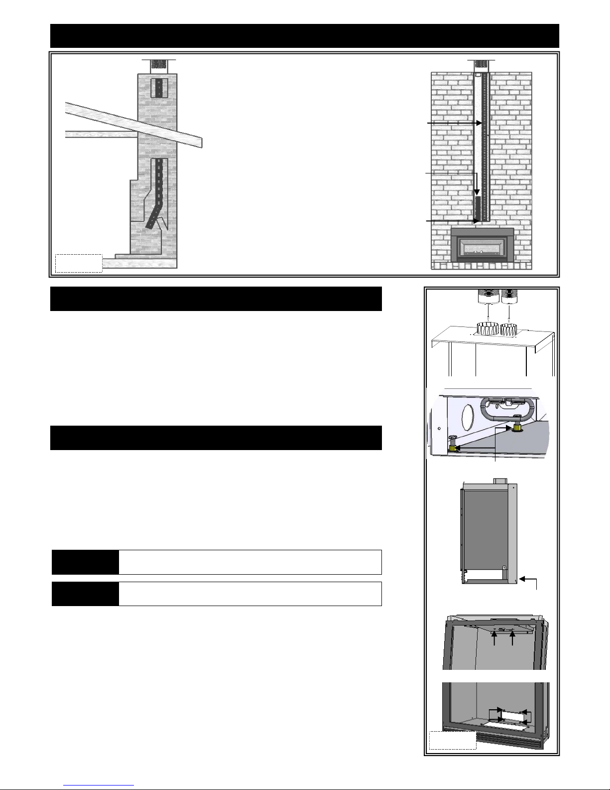
VENTING INSTALLATION KOZY HEAT #815-CL CO-LINEAR VENT SYSTEM (cont.)
3" ex haust fl ex pi pe mus t be conne ct ed to
collar on fireplace insert and termination cap
Minimum 4ft. (1.22m) section of 3" combustion
air flex pipe DO NOT block pipe end with
ins ulat ion or a ny other se al in g m ateri al s
Seal area around ve nt pipes with non-faced
fiberglass insulation
Figure 11a
CONNECT #815-CL VENT SYSTEM TO AIR DUCT
1. Place air duct (previously removed from insert top, page 9) into existing fireplace
opening.
2. Place a bead of sealant (provided) around 4” exhaust pipe. Slide exhaust pipe inside
4" collar air duct. Secure with (3) ½" self-tapping screws, provided. Apply additional
sealant around joint to ensure an air-tight seal.
3. Apply a liberal bead of sealant (provided) around 3” collar on the air duct. Slide 3”
combustion intake pipe over the collar. Secure with (3) ½" self-tapping screws,
provided. To ensure an air-tight seal, apply additional sealant aroun d joint.
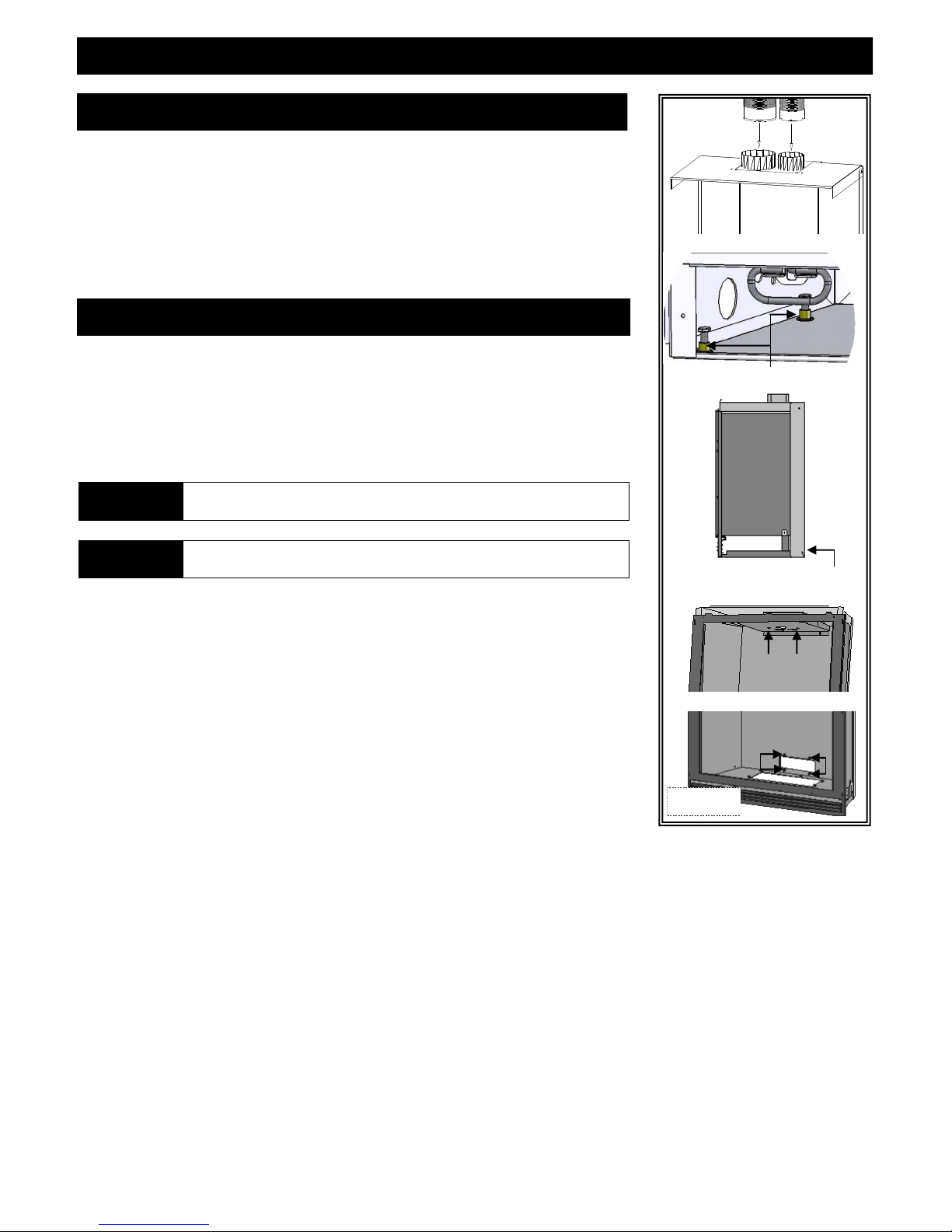
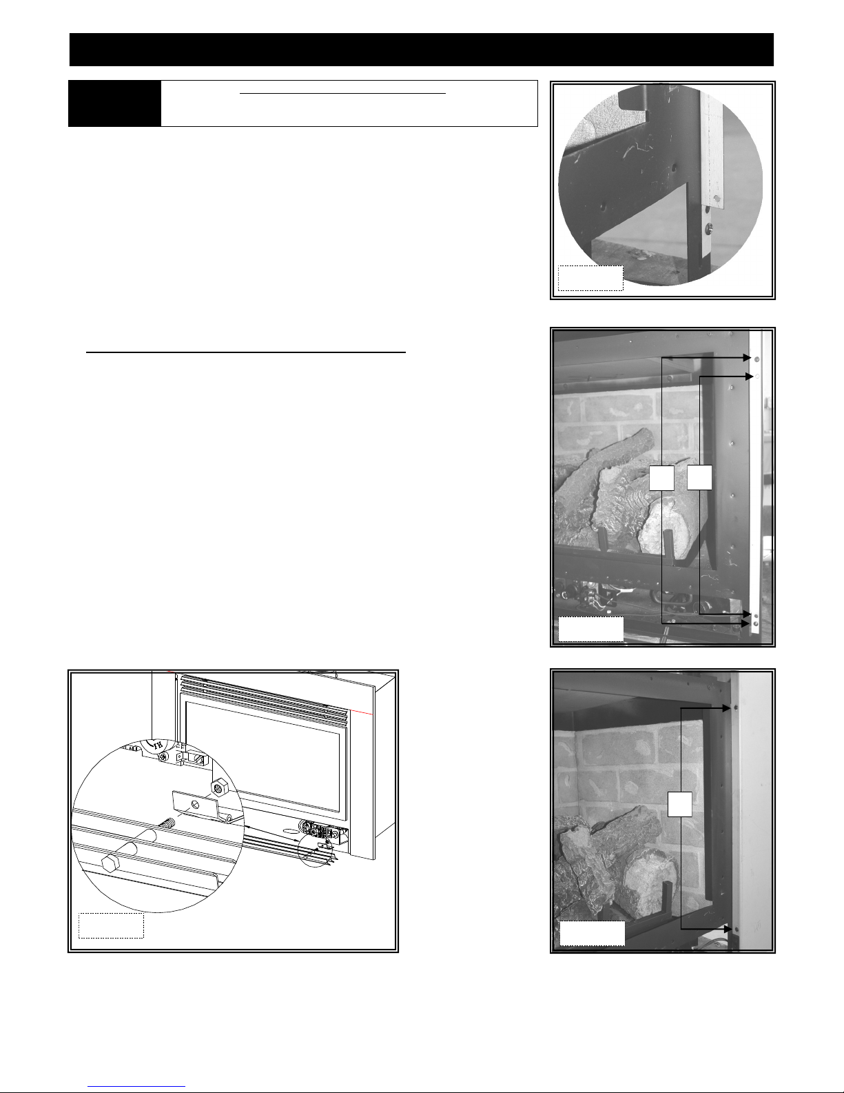
ATTACH AIR DUCT TO INSERT
1. Slide insert into fireplace opening.
2. If necessary, level insert by threading leveling bolts (included in components packet)
into nuts mounted inside lower air passage.
3. Attach air duct to insert by aligning two holes in insert top to studs on each side of 4"
exhaust duct, and four holes at back of insert to mounting studs at lower end of air
duct.
NOTE
IMPORTANT Before completing steps 4 & 5, ensure air duct gasket is properly seated.
4. Locate baffle with seasonal heat dump inside firebox, noting (2)access holes on each
side of heat dump. Secure air duct to insert through access holes with (2) 1/4" nuts.
5. Using a 7/16” wrench, secure lower end of air duct to insert firebox with (4) 1/4"
nuts.
If installing optional #911-MSP:
Align (4) holes in insert face to corresponding holes in masonry side panels. Secure with
remaining screws included with kit.
To prevent rattling noises that may occur during fan operation, position air
duct back and sides on the OUTSIDE of insert bottom flanges.
Leveling legs (2 per side)
Position air duct back and sides outside
insert bottom flanges
Figure 11b
11
VENTING INSTALLATION
KOZY HEAT #815-CA CO-AXIAL VENT SYSTEM
NOTE
Carefully extend 4” and 6” flex pipes and extension kit (if used) to equal total chimney length required.
If an extension kit is used, it must be connected to 4" exhaust and 6" combustion air intake pipe included with #815-CA Vent Kit.
EXHAUST CONNECTION:
Apply liberal bead of sealant (provided) around 4” exhaust adaptor (with external notches) on extension kit and slide into female connector
on end of 4” exhaust pipe. Secure with 3 self-tapping screws, (provided). To ensure an air-tight seal, apply additional sealant at point of
connection.
COMBUSTION INTAKE CONNECTION:
Slide extended 6" combustion intake pipe included with 815-CA kit over extended 4" exhaust pipe included with 815-CA kit. Apply liberal
bead of sealant (provided) around 6” combustion intake adaptor (with external notches) on extension kit and slide it over extended 4"
exhaust pipe extension and into female end of 6” combustion intake pipe. Secure with 3 self-tapping screws (provided). To ensure an
air-tight seal, apply additional sealant at point of connection. The 4" exhaust pipe is now inside 6" intake pipe.
A. Apply liberal bead of sealant (provided) around inside edge of 4” exhaust pipe, (end without collar) and slide it onto 4" collar on
vent cap. Secure with 3 equally spaced self-tapping screws through both sections. Apply additional sealant around joint to ensure
an air-tight seal.
B. Apply liberal bead of sealant (provided) around inside edge of 6” combustion intake pipe, (end without collar) and slide it onto 6”
collar on vent cap. Secure with 3 equally spaced self-tapping screws through both sections. Apply additional sealant around joint
to ensure an air-tight seal. The 4" exhaust pipe will be inside the 6" combustion intake pipe.
The co-axial pipe included with this vent system is designed for chimneys up to 32 ft. ( 9.75 m). If additional length is required,
Part #716-A is available to extend the venting to a maximum of 40 ft. (12.19 m).
The 4" exhaust flex pipe and 6" combustion air flex pipe are coiled and packaged separately.
Figure 12a
RUN VENTING THROUGH EXISTING CHIMNEY
We strongly suggest wrapping first 3 ft.(914 mm) of vent system below
termination cap with non-faced fiberglass insulation (secure with wire)
before running it through existing chimney. This will prevent cold air
from coming down existing chimney.
If offsets are present in existing chimney, it may be easier
NOTE
A. Guide ropes, if used, and flexible pipes down existing chimney.
B. To secure chimney termination cap to existing chimney, apply
liber al bead of se ala nt aro und to p of exi sti ng chi mne y, set
termination cap into position. Secure with (4) 1-1/2” self-drilling
screws (provided).
to place a weighted rope around end of each pipe to guide
them through it. DO NOT ATTEMPT TO TIE ONE
ROPE AROUND BOTH PIPES.
Figure 12b
12
VENTING INSTALLATION
CONNECT #815-CA CO-AXIAL VENT SYSTEM TO AIR DUCT
A. Place air duct into existing fireplace opening.
B. Place bead of sealant (provided) around 4” flex pipe and slide into 4” collar on air duct.
Secure with (2) self-tapping screws (provided).
Apply additional sealant around joint to ensure an air-tight seal.
C. Apply bead of sealant around 6” collar on flex pipe and slide into 6” collar on air duct.
Secure with (1) self-tapping screw (provided) through center front of this connection. Apply
additional sealant around joint to ensure an air-tight seal.
ATTACH AIR DUCT TO INSERT
1. Slide insert into fireplace opening.
2. If necessary, level insert by threading leveling bolts (included in components packet) into
nuts mounted inside lower air passage.
3. Attach air duct to insert by aligning two holes in insert top to studs on each side of 4"
exhaust duct, and four holes at back of insert to mounting studs at lower end of air duct.
Leveling legs (2 per side)
NOTE
IMPORTANT Before completing steps 4 & 5, ensure air duct gasket is pro perly seated.
4. Locate baffle with seasonal heat dump inside firebox, noting (2) access holes (A) on each
side of heat dump. Secure air duct to insert through access holes with (2) 1/4" nuts.
5. Using a 7/16” wrench, secure lower end of air duct to insert firebox with (4) 1/4" nuts.
To p re v e nt r a tt l i ng n o is e s t h a t ma y oc c ur d ur i n g fa n o p e ra t i o n,
position air duct back and side flanges on OUTSIDE of insert bottom flanges.
If installing optional #911-MSP:
Align (4) holes in insert face to corresponding holes in masonry side panels.
Secure with remaining screws included with kit.
Position air duct back and sides outside
insert bottom flanges
Figure 13a
13
CONTROL BOARD REMOVAL / INSTALLATION
CAUTION
NOTE Your components may look slightly different than ones shown.
If burner and/or pilot have been burning, use appropriate protection to avoid burns or damage to personal property before
removing any components.
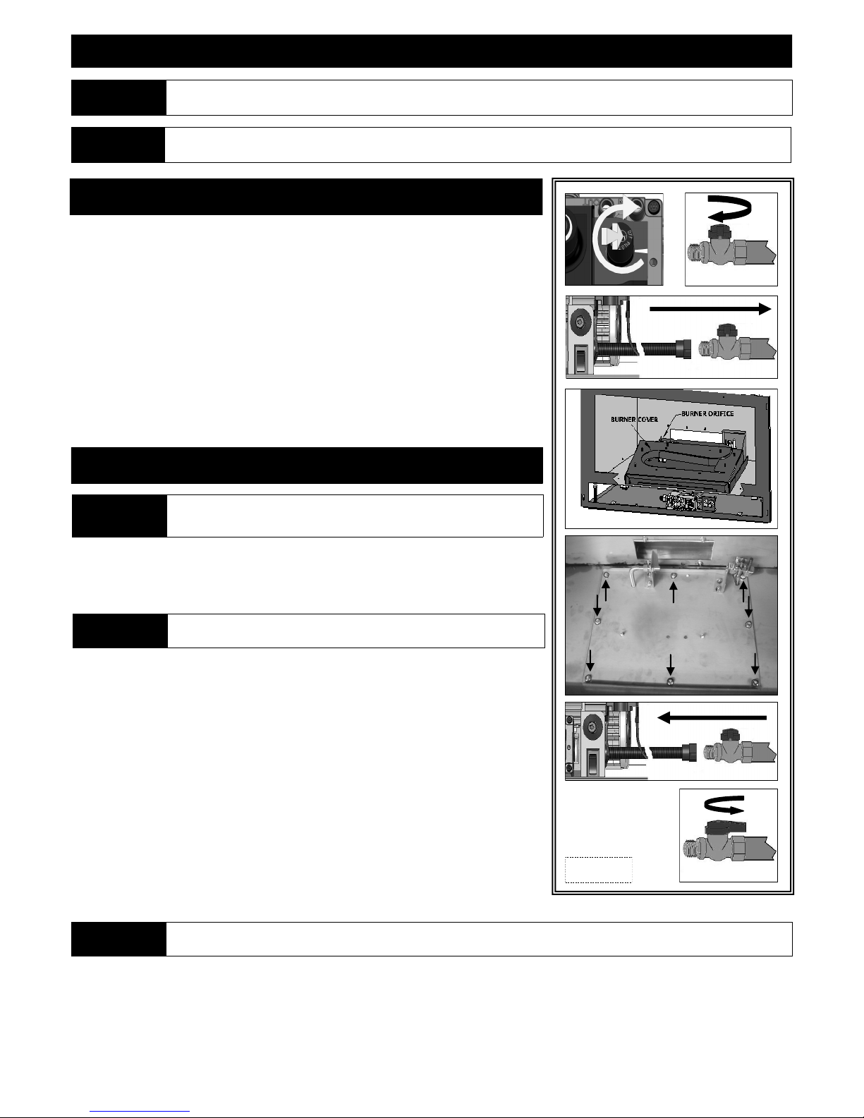
CONTROL BOARD REMOVAL
1. Turn fireplace off.
2. Shut off gas supply at manual shut-off valve.
3. Disconnect gas line flex tube from manual shut-off valve.
4. Disconnect any wall switch, remote control, or thermostat wires fr o m TH / TH TP
terminals on gas valve, or unplug all components from electrical outlet, disconnect
all wiring harnesses attached to gas valve.
5. Remove glass assembly and logs.
6. Remove burner assembly and burner heat shield.
7. Remove (8) nuts securing control board. Lift board up and out of firebox.
CONTROL BOARD INSTALLATION
DO NOT OPERATE THIS FIREPLACE WITHOUT SEALING GASKET IN PLACE
WARNING
(LOCATED UNDER CONTROL BOARD).
IF GASKETING IS DAMAGED, IT MUST BE REPLACED.
1. Place control board in firebox, aligning holes in control board with mounting studs in
firebox bottom. Ensure sealing gasket in in place on firebox bottom!
Secure control board to firebox bottom with (8) 1/4” nuts. Place burner heat shield
over control board (flanges facing down).
CAUTION
Before securing, check that all wires are clear and unobstructed. Do not
allow any wires or gas flex line to come in contact with fan terminals.
2. Install burner assembly; burner tube is positioned over burner orifice and sides are
inside control board flanges.
3. Install pilot shield around pilot assembly.
4. Connect gas line to manual shut-off valve.
5. Re-onnect any wall switch, remote control or thermostat wires to terminals on valve
marked TH / THTP, or reconnect all wiring harnesses to gas valve. Plug components
into electrical outlet.
6. Install log set.
7.
8. Install glass frame assembly.
9. Verify proper log placement, operation of insert and any electrical components.
Figure 14a
CAUTION CHECK ALL CONNECTIONS FOR LEAKS WITH SOAPY WATER, WHETHER FIELD OR FACTORY MADE.
14
ZC SHROUD ASSEMBLY AND INSTALLATION
Shroud assembly includes: (1) Shroud top (8) Phillips head screws
(1) Shroud left side (2) Shroud extensions
(1) Shroud right side with on/off rocker switch mounting hole
You will also require a grill set or a clean face frame (sold separately).
911 / 911-RAD : You will need the following items from insert components packet: Rocker Switch Wires and On/Off Rocker Switch.
Grill option: Remove nuts from upper grill. Place grill rods through holes in shroud top section. Secure with nuts. If necessary, recess
upper grill by re-positioning in one of three mounting holes.
Clean Face frame option: Follow instructions included with clean face frame.
1. Secure right and left shroud sections to top section by aligning (2) holes in side sections to holes in top section. Secure with phillips
head screws (2 ea. side).
OPTIONAL Attach shroud extensions by aligning slots in shroud with desired hole in shroud extension. Secure with phillips head screws.
Grill attachment holes
Phillips head screws
Attach shroud extensions by aligning slot in
shroud with desired hole in shroud extension.
Secure with phillips head screws.
Figure 15a
911 / 911-RAD: Snap rocker switch into place on shroud. Slide one connector on each rocker switch wire to the rocker switch.
2. Attach shroud to insert by placing tabs on left and right shroud pieces into slots in insert. The shroud will set into place.
911 / 911-RAD: Slide remaining connectors on rocker switch wires to terminals on gas valve marked TH / THTP.
Grill option: Remove nuts from lower grill, insert grill bolts through lower hinges on insert. Attach and tighten nuts.
Tabs
Holes
Figure 15b
15
MASONRY SHROUD ASSEMBLY & INSTALLATION
Shroud assembly includes: (1) Shroud top (8) Phillips head screws
(1) Shroud left side (1) Set ‘inside fit’ brackets
(1) Shroud right side with on/off rocker switch mounting hole
You will also need upper grill from grill set or a clean face frame (sold separately).
911 / 911-RAD: You will need the following items from insert components packet: Rocker switch wires and On/Off Rocker Switch
Grill option: Remove nuts from upper grill. Place grill rods through holes in shroud top section. Secure with nuts.
Clean Face frame option: Follow instructions included with clean face frame.
1. Secure right and left shroud sections to top section by aligning (2) holes in side sections to holes in top section. Secure with phillips
head screws (2 ea. side).
911 / 911-RAD: Snap rocker switch into place on shroud. Slide one connector on each rocker switch wire to the rocker switch.
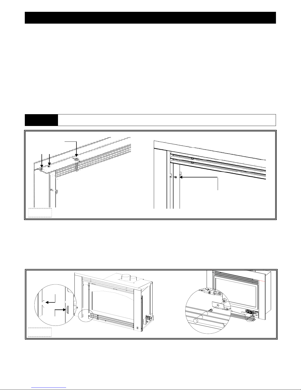
2. Attach shroud to insert by inserting tabs (A) on left and right shroud sections to holes (B) in insert face. The shroud will set down into
place.
Screws secured from bottom.
Figure 16a
OUTSIDE FIT APPLICATIONS:
911 / 911-RAD: Slide remaining connectors on rocker switch wires to terminals on gas valve marked TH / THTP.
Grill option: Remove nuts from lower grill, insert grill bolts through lower hinges on insert. Attach and tighten nuts.
Tabs
Holes
Figure 16b
Snap On/Off rocker switch into
mounting hole as shown.
INSIDE FIT APPLICATIONS: (You will require ‘inside fit’ brackets included with shroud assembly).
1. Remove glass frame assembly.
2. Referring to illustration at right, use tin snips to remove lower end of (4) mounting tabs on shroud
side sections.
Figure 16c
16
MASONRY SHROUD ASSEMBLY & INSTALLATION cont.
IMPORTANT- MOUNTING BRACKET ORIENTATION. Figure 17a.
IMPORTANT
1. Align holes in mounting brackets to corresponding holes in insert face, making sure
brackets are positioned as shown in Figure 17a.
Secure with screws provided (Figure 17b).
2. Position tabs (lower end previously removed) on shroud into slots in insert face,
aligning oblong holes on inside flange of shroud side sections to holes in mounting
brackets. Secure with (4) screws (C), 2 each side. Figure 17c.
911 / 911-RAD: Slide remaining connectors on rocker switch wires to terminals on gas
valve marked TH / THTP.
Grill option: Remove nuts from lower grill, insert grill bolts through lower hinges on
insert.
OPTIONAL MASONRY PANEL INSTALLATIONS:
1. Remove screw s (A) (2 ea. side) securin g mason r y pan e l s . Figur e 17 b .
2. Align holes in mounting brackets to corresponding holes in insert face & masonry
panels, making sure brackets are positioned as shown in Figure 17b. Secure with
screws removed in step1and included in shroud components packet.
3. Position tabs (lower end previously removed) on shroud into slots in insert face,
aligning oblong holes on inside flange of shroud side sections to holes in mounting
brackets. Secure with (4) screws (C), 2 each side. Figure 17c.
911 / 911-RAD: Slide remaining connectors on rocker switch wires to terminals on gas
valve marked TH / THTP.
Grill option: Remove nuts from lower grill, insert grill bolts through lower hinges on
insert. Attach and tighten nuts. Figure 17d.
Right mounting bracket is notched out at the bottom.
Flanges on both mounting brackets face the inside of insert.
Figure 17a
A
B
Figure 17d
Figure 17b
C
Figure 17c
17
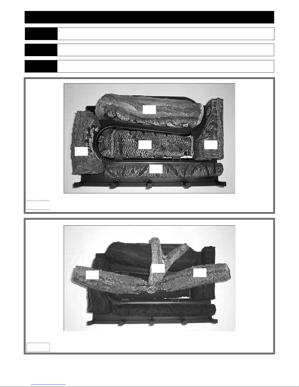
#932-500A LOG SET INSTALLATION
ATTENTION If converting to LP (propane) gas, do so now before installing log set. Follow instructions included with conversion kit.
NOTE Log numbers are located on bottom of each log. Refer to following instructions and illustrations for proper placement.
CAUTION
Figure 18a
Do not place logs directly over burner port holes. Improper log placement may affect flame appearance and cause excessive
soot to build up on logs and glass.
AD
BI
HB
AG
AJ
Align notches on bottom of BI log with brackets in burner cover. Set down into position.
Position AD, AG, HB & AJ logs onto burner cover, pressing down onto pins.
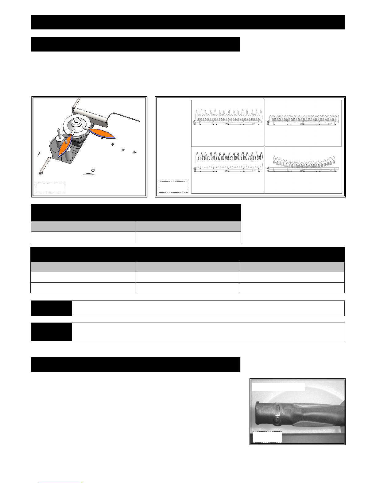
M
Figure 18b
Use a steel or stiff bristle nylon brush to distribute Rock Wool Embers onto logs and burner.
C
M
Align hole in bottom of right M log to knob on HB log.
Position remaining M log and C log as shown above.
18
FINALIZING THE INSTALLATION
FLAME APPEARANCE:
Flame appearance is affected by several factors including altitude, venting configuration and fuel quality. Although the vent uri setting has
been factory set, adjustments may be necessary for optimal performance and visual aesthetics.
When fireplace is first lit, the flames will be blue. Flames will gradually turn yellowish-orange during first 15 minutes of operation. If
flames remain blue, or become dark orange with evidence of sooting (black tips), the burner tube venturi may need adjustment.
Short blue flames
venturi open too far
Lifting (ghosting) flames
Improper Venting
Gas pressure too high
Figure 19a
Correct pilot flame
Figure 19b
Lazy yellow flames - ideal
Dark orange flames / black tips
Venturi closed too far
Excessive burner media
FACTORY SET BURNER TUBE VENTURI SETTINGS
(ADJUST AS NECESSARY FOR YOUR INSTALLATION)
NATURAL GAS LP (PROPANE) GAS
3/16” (5mm) open 5/8” (16mm)
BURNER TUBE VENTURI ADJUSTMENT GUIDELINES
VENTURI POSITION FLAME COLOR VENTURI ADJUSTMENT
Closed too far Dark orange flame with black tips Open venturi setting slightly
Open too far Blue flames Close venturi setting slightly
NOTE If soot is present, check log positioning before adjusting burner venturi. Logs must not block burner ports.
SLI G HT A D J U STM EN T S T O B U R NER V E N T U R I O PE N I N G C RE A T E D RAMA TI C R E SUL TS . A DJ U S T A T S LI G H T
IMPORTANT
IN CREMENT S U N T I L D E S I R E D L O O K I S A C HI E VED. AL WAY S B U R N F I R E P LAC E F OR A T L E AST 1 5 M I N U T ES
AND ALLOW TIME TO COOL BEFORE MAKING ANY FURTHER ADJUSTMENTS.
TO ADJUST VENTURI:
1. Remove glass frame assembly.
2. Remove log set.
3. Remove burner assembly.
4. Loo sen s c rew on burner ve n t uri an d adjust a s neces sar y . Tighten s cr e w.
5. Reinstall all components previously removed.
6. Light fireplace and wait 15 minutes before determining if any further adjustments
are needed.
BURNER VENTURI
Figure 19c
19

FINALIZING THE INSTALLATION
RESTRICTOR USAGE:
Turn fireplace on and allow to burn for 15 minutes.
If flames indicate there is excessive draft (flickering, short flames), a restrictor may be necessary.
If flames indicate insufficient draft (lifting or ghosting flames), a previously installed restrictor may need to be modified or removed.
WARNING
TO AVOID PROPERTY DAMAGE OR PERSONAL INJURY, ALLOW FIREPLACE AMPLE TIME TO COOL BEFORE MAKING ANY
ADJUSTMENTS AND / OR INSTALLATIONS.
RESTRICTOR TROUBLESHOOTING
FLAME APPEARANCE DRAFT PROBLEM RESTRICTOR SOLUTION
Short, flickering Excessive draft - not enough restriction Add restrictor
Lifting or ghosting* Insufficient draft - too much restriction Remove inner ring (s) on restrictor or
remove restrictor
* Improper venting installation may cause flames to lift or “ghost” - a dangerous situation. Inspect flames after installation to ensure proper
performance. If determined that venting is correct, and the restrictor has been removed, yet flames are still lifting or ghosting, shut off gas
supply to fireplace and call a qualified service technician.
RESTRICTOR INSTALLATION / MODIFICATION (after termination completion):
If it is determined that a restrictor is needed or restrictor modification is required after termination is installed, access can be reached
through insert baffle. Please remove logs and refractory to avoid damaging these components.
1. Remove (2) nuts securing baffle. Remove baffle to expose venting.
2. Depending on your specific needs, determined by the chart above along with other factors, make necessary modifications.
3. If installation of a restrictor (included in components packet) is necessary, bend tabs on restrictor to approx. 80 degree angles to create
tension when inserted into the exhaust pipe on fireplace insert. Insert restrictor into 4” exhaust pipe with tabs pointing to wards you.
4. If modification is necessary, remove restrictor by pulling it down and out of 4” exhaust pipe.
5. Reinstall baffle, secure with (2) nuts previously removed.
6. Reinstall refractory and log set.
7. Attach glass frame assembly and light fireplace. Wait 15 minutes before determining if any further modifications are necessary.
Remove baffle to expose venting.
Figure 20a
Large Restrictor Bend tabs to approx. 80 degree
Remove tab (s) to
create small restrictor
angles to create tension to hold
itself in place when installed.
20
FINALIZING THE INSTALLATION
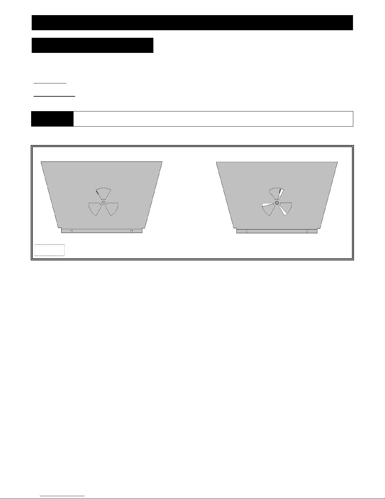
SEASONAL HEAT DUMP
This fireplace insert has been manufactured with a heat dump damper located at the inside top of firebox. This allows infinite
control over the amount of heat emitted into the living area without affecting flame height.
INSTALLER: Please install this fireplace insert with the heat dump in the closed position.
HOMEOWNER: This fireplace insert has been installed with the heat dump in the closed position and will operate at its peak efficiency
at this setting. The heat dump may be opened as much as necessary to maintain desired heat level.
CAUTION
Remove glass frame assembly. Open or close heat dump as desired. Re-install glass frame assembly.
Figure 21a
Do not attempt to adjust heat dump opening if fireplace has been in operation. Allow ample time to cool or use appropriate
protection to avoid serious burns and / or property damage.
Shown in closed position Shown in partial open position
21
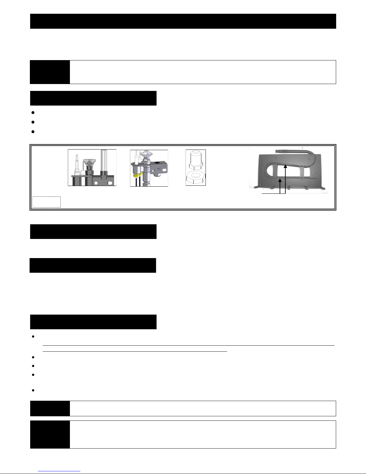
MAINTENANCE
The appliance is required to be inspected at least once a year by a professional service person.
The compartment below firebox must be cleaned at least once a year, more frequent cleaning may be required due to excessive lint from carpeting,
bedding materials, or other fibrous materials. Use a vacuum to clean all components at least once a year.
INSTALLAT ION AND REPAIR SHOULD BE DONE ONLY BY QUALIFIED SERVICE PER SON. THE APPLIANCE SHOULD BE
NOTE
CONTROL BOARD SYSTEM
Annual cleaning of burner system is required. Vacuum all components thoroughly.
Visually check for blocked port holes, especially near the pilot. Blocked port holes may cause delayed ignition.
Visually check pilot light and burner when in operation. Flames should be steady, not lifting or floating.
INSPE CTED BEFORE USE AND ANNUALLY BY A QUALIF IED SERVICE PERSON. MORE FREQUENT CLEANI NG MAY BE
REQUIRED DUE TO EXCESSIVE LINT FROM CARPETING, BEDDING MATERIALS, ETC. IT IS IMPERATIVE THAT CONTROL
COMPARTMENTS, BURNERS AND CIRCULATION AIR PASSAGEWAYS OF THE APPLIANCE BE KEPT CLEAN.
Figure 22a
911 Pilot
911-RAD Pilot
911-MV Pilot
911-IPI Pilot
Burner Orifice
Burner Ports
FAN
The fan should be disconnected from electrical current, and cleaned (vacuumed) every six months. The bearings are sealed and require no oiling.
VENT SYSTEM
Annual examination of venting system by a qualified agency is required.
IF VENT-AIR INTAKE SYSTEM IS DISASSEMBLED FOR ANY REASON, RE-INSTALL PER INSTRUCTIONS PROVIDED WITH INITIAL
INSTALLATION.
The flow of combustion and ventilation air must not be obstructed.
GLASS CLEANING & REPLACEMENT
Clean glass only when cool and only with non-abrasive cleansers.
WARNING: DO NOT OPERATE APPLIANCE WITH GLASS/FRAME ASSEMBLY REMOVED, CRACKED OR BROKEN. REPLACEMENT OF THE
GLASS SHOULD ONLY BE PERFORMED BY A LICENSED OR QUALIFIED SERVICE PERSON.
Use protective gloves to handle any broken or damaged glass assembly components.
The glass assembly, part #700-08T, shall only be replaced as a complete unit, as supplied by Hussong Mfg. Co., Inc.
Replacement of glass assembly, part #700-08T, must only be performed by a licensed or qualified service person.
DO NOT SUBSTITUTE MATERIALS.
Do not strike or slam glass door assembly.
IMPORTANT
CAUTION
ANY SAFETY SCREEN OR GUARD REMOVED FOR SERVICING MUST BE REPLACED PRIOR TO OPERATING THE APPLIANCE.
LABEL ALL WIRES PRIOR TO DISCONNECTION WHEN SERVICING CONTROLS. WIRING ERRORS CAN CAUSE IMPROPER AND
DANGEROUS OPERATION. VERIFY PROPER OPERATION AFTER SERVICING.
KEEP APPLIANCE AREA CLEAR OF COMBUSTIBLE MATERIALS, SUCH AS GASOLINE AND OTHER FLAMMABLE VAPORS AND
LIQUIDS.
22

LIMITED WARRANTY
KOZY HEAT LIMITED 10 YEAR WARRANTY
This limited 10 Year Warranty will not become effective until the Warranty Registration Form has been completed and mailed to
Hussong Manufacturing Co., Inc., P.O. Box 577, Lakefield, MN 56150. This registration form must be received within 30 days of
installation. Failure to do so may result in delayed warranty coverage and submission of proof of purchase will be required.
Hussong Manufacturing Co., Inc. warranties to the original purchaser of this Kozy Heat Fireplace, that it is free of defects in materials
and workmanship at the time of manufacture.
Subject to the following conditions & requirements, Hussong Manufacturing Co., Inc. extends the following limited warranty un der
normal use and service, with respect to the Kozy Heat line of gas burning fireplaces.
YEAR 1: Subject to the conditions & requirements listed below, within the first year from date of purchase, Hussong Manufacturing Co.,
Inc. shall, at its discretion, replace or repair any such defect in material or workmanship, at Hussong Manufacturing Co., Inc.’s expense,
including reasonable labor costs to repair or replace the defective component, if a factory pre-authorization is given for the repair.
YEARS 2-10: Subject to the conditions & requirements listed below, beginning with the first day of the second year and continuing
through the tenth year, Hussong Manufacturing Co., Inc., will at its discretion, provide repair or replacement parts at curre nt list prices
for any defect in material or workmanship of components, including optional components and accessories (if available). Husson g
Manufacturing Co., Inc. shall not be responsible for any installation, labor, transportation of other indirect costs.
LIMITATION OF LIABILITY
To make a claim under this warranty, the purchaser must first contact the dealer/installer from whom the fireplace was purchased.
This limited warranty will be void if the fireplace is not installed by a qualified installer and according to the installation instructions.
Use of unauthorized components will make this warranty null and void.
This limited warranty also is void if the fireplace is not operated, at all times, according to the operating instructions furnished.
This warranty is limited to defects in material and workmanship. It does not apply to any product that has been subject to negligence,
misapplication, improper installation.
No person is authorized to extend the time of this warranty or to accept on Hussong Manufacturing Co., Inc.’s behalf any additional
obligation of liability connected with the unit.
It is expressly agreed and understood that this warranty is Hussong Manufacturing Co., Inc.’s sole obligation and purchaser’s exclusive
remedy for defective fireplace equipment. Hussong Manufacturing Co., Inc. shall not be liable for any consequential, incidental or
contingent damages whatsoever. The foregoing warranty is exclusive and in lieu of all other expressed warranties. Hussong
Manufacturing Co., Inc. shall not be held to implied warranties or merchantability and fitness for a particular purpose. This warranty
replaces all previous warranty policies.
Some states do not allow the exclusion or limitation of incidental or consequential damages or limitations on how long an implied
warranty lasts, so the above limitations or exclusions may not apply to you. This warranty gives you specific legal rights and you may
also have other rights which vary from state to state.
Hussong Manufacturing Co., Inc. reserves the right to make changes at any time, without notice, in design, material, specifications and
prices. Hussong Manufacturing Co., Inc. reserves the right to discontinue models and products.
WARRANTY CONDITIONS & REQUIREMENTS:
1. You are the original purchaser. This warranty is not transferable.
2. Installation of the fireplace is performed by a qualified installer.
3. Installation and operation must comply with installation and operation instructions.
4. Paint and glass gaskets are covered for 30 days from date of purchase.
5. Remote controls and all optional accessories are covered for 1 year from date of purchase.
6. This warranty does not offer coverage for Light Bulbs or Batteries (whether factory, dealer or installer supplied). This includes any
damage stemming from either component’s nonuse.
7. Components broken, (including glass panels), during shipping, careless handling of components, or defects resulting from improper
installation, misuse of the fireplace and components are not covered under this warranty.
8. This warranty does not cover any part of the fireplace or any components which have been exposed to or submerged under water.
9. Hussong Manufacturing Co., Inc. must be notified by the dealer the fireplace was purchased from or a qualified installer/service
technician of the defect.
10. Annual service of the fireplace as required in the installation manual, is performed by a qualified installer/service technician.
(Copies of such service records may be required to claim a warranty).
11. All previous warranty/service has been performed by a qualified installer or service technician.
Effective September 01, 2011
23
LIFETIME WARRANTY
LIFETIME WARRANTY
THIS LIFETIME WARRANTY COVERAGE WILL BE EXTENDED AS DESCRIBED BELOW PROVIDED ALL WARRANTY
CONDITIONS AND REQUIREMENTS ARE MET AS OUTLINED IN THE 10 YEAR LIMITED WARRANTY POLICY.
LIFETIME WARRANTY COVERAGE
LIFETIME WARRANTY IS EXTENDED AS FOLLOWS: Hussong Manufacturing Co., Inc. warranties to the original purchaser that the
firebox, heat exchanger, fiber logs, burner tube and glass panel of this Kozy Heat Fireplace will not be defective in materia l or
workmanship under normal use and service for as long as you own this product. If any of these components fail due to defects in material
and workmanship under normal use and service, Hussong Manufacturing, Co., Inc. will, at its sole discretion, repair or replace the defective
component. This LIFETIME WARRANTY does not cover any installation, labor, transportation or other indirect cost arising from
defective components.
LIMITATION OF LIABILITY
This Lifetime Warranty will be void if the fireplace is not installed by a qualified installer and according to the installation instructions.
Use of unauthorized components will make this warranty null and void. This Lifetime Warranty also is void if the fireplace is not operated,
at all times, according to the operating instructions furnished. This warranty is limited to defects in material and workmans hip of
components specified. It does not apply to any product that has been subject to negligence, misapplication, improper installa tion.
No person is authorized to extend the time of this Lifetime Warranty or to accept on Hussong Manufacturing Co., Inc.’s behalf any
additional obligation of liability connected with the unit.
Hussong Manufacturing Co., Inc. may fully discharge all obligations with respect to this Lifetime Warranty by refunding the w holesale
price of the defective component(s).
It is expressly agreed and understood that this Lifetime Warranty is Hussong Manufacturing Co., Inc.’s sole obligation and or iginal
purchaser’s exclusive remedy for defective fireplace equipment. Hussong Manufacturing Co., Inc. shall not be liable for any
consequential, incidental or contingent damages whatsoever other than those incurred by Hussong Manufacturing Co., Inc. to repair or
replace the defective component. The foregoing warranty is exclusive and in lieu of all other expressed warranties. Hussong M anufacturing
Co., Inc. shall not be held to implied warranties, including but not limited to the implied warranties or merchantability and fitness for a
particular purpose. This lifetime warranty replace all previous lifetime warranty policies.
Hussong Manufacturing Co., Inc. reserves the right to make changes at any time, without notice, in design, material, specific ations and
prices. Hussong Manufacturing Co., Inc. reserves the right to discontinue models and products.
To activate this Lifetime Warranty coverage, this registration card must be completed and mailed with your completed 10 Year
Limited Warranty form within 30 days of installation to the following address:
Hussong Manufacturing Co., Inc.
P.O. Box 577
204 Industrial Park Drive
Lakefield, MN 56150-0577
PURCHASER NAME:
ADDRESS:
TELEPHONE:
INSTALLER NAME:
ADDRESS:
TELEPHONE:
CUT ALONG DOTTED LINE
INSTALLATION DATE:
MODEL #:
SERIAL #:
Sept. 2011
24
Supplemental Installation and Homeowner
I n f o r m a t i o n Ma n u a l f o r 9 1 1 Mo d e l :
DIRECT VENT GAS FIREPLACE
IMPORTANT: This supplemental installation and homeowner manual is to be used in
conjunction with 911 INSTALLATION MANUAL. Read both manuals before installing and
operating appliance.
INSTALLER: Leave this manual with the appliance.
CONSUMER: Retain this manual for future reference.
WARNING: Improper installation, adjustment, alteration, service or maintenance
can cause injury or property damage. Refer to fireplace installation manual and this
manual. For assistance or additional information consult a qualified installer, service
agency or the gas supplier.
WARNING: If the information in these instructions is not followed exactly, a fire
or explosion may result causing property damage, personal injury or loss of life.
—Do not store or use gasoline or other flammable vapors and liquids in the vicinity
of this or any other appliance.
WHAT TO DO IF YOU SMELL GAS:
◙ Do not try to light any appliance.
◙ Do not touch any electrical switch: do not use any phone in your building.
◙ Immediately call gas supplier from a neighbors phone. Follow the gas supplier
instructions.
◙ If you cannot reach your gas supplier, call the fire department.
— Installation and service must be performed by a qualified installer, service
agency or the gas supplier.
English and French Installation Manuals
Available Through Your Local Dealer or
Visit Our Website at www.kozyheat.com
WARNING
HOT GLASS WILL CAUSE BURNS.
DO NOT TOUCH GLASS UNTIL COOLED.
NEVER ALLOW CHILDREN TO TOUCH GLASS.
Report No. 216-F-22b-6.5
JUNE 2012
911-SUP-REV-01
www.kozyheat.com

TABLE OF CONTENTS
SAFETY INFORMATION
Safety Information 2
SPECIFICATIONS
Components List 3
Gas Pressure Requirements / BTU’s 3
THERMOSTAT / WALL SWITCH / REMOTE
Thermostat / Wall Switch / Remote 4
OPERATING INSTRUCTIONS
Valve and Pilot Assembly Components 5
Lighting and Shutdown Instructions 6-8
Pressure Testing 9
TROUBLESHOOTING
Troubleshooting 10-12
CONVERSION KIT INSTRUCTIONS
Conversion Kit Instructions 13-15
MAINTENANCE
Maintenance 16
REPLACEMENT PARTS
Replacement Parts 17
1
SAFETY INFORMATION
This fireplace has been tested by OMNI-Test Laboratories, Portland, Oregon and complies with:
ANSI Z21.88-2009 “Standard for Vented Gas Fireplace Heaters.”
This installation must conform with local codes, or in the absence of local codes, with the National Fuel Gas Code, ANSI Z223.1/NFPA 54.
Installation and repair should be done only by a qualified service person. The appliance should be inspected by a
qualified service person before use. Annual inspection by a qualified service person is required to maintain warranty.
More frequent cleaning may be required due to excessive lint from carpeting, bedding materials, etc. It is imperative
th a t con trol co mpa r t m e n t s, burners a n d c i rc ulation air p a s sag eways of the a p p l ia nce be kept c l ea n.
This fireplace insert is to be installed into a solid fuel masonry or factory built non-combustible fireplace that has been
i n s t a ll ed i n a c c o r d a nc e w i t h t he N at i o n a l , P ro vi nc ia l, S ta te a n d l o c al b ui ld in g c o d es .
Children and adults should be alerted to the hazards of high surface temperatures and should stay away to avoid burns
or clothing ignition.
Young children should be carefully supervised when they are in the same room as the appliance. Toddlers, young
children and others may be susceptible to accidental contact burns. A physical barrier is recommended if there are at
risk individuals in the house. To restrict access to a fireplace or stove, install an adjustable safety gate to keep toddlers ,
young children and other at risk individuals out of the room and away from hot surfaces.
Clothing or other flammable material should not be placed on or near the appliance.
Adequate accessibility clearances for servicing and proper operation must be maintained.
This appliance must not share or be connected to a chimney flue serving any other appliance.
Keep area around the appliance clear of combustible materials, gasoline and other flammable vapor and liquids.
The flow of combustion and ventilation air must not be obstructed.
Due to high temperatures the appliance should be located out of traffic and away from furniture and draperies.
The glass front or any part removed for servicing the appliance must be replaced prior to operating the appliance.
Work should be done by a qualified service technician.
Clean glass only when cool and only with non-abrasive cleansers.
WARNING: DO NOT OPERATE APPLIANCE WITH THE GLASS/FRAME ASSEMBLY REMOVED, CRACKED
OR BROKEN. REPLACEMENT OF THE GLASS SHOULD ONLY BE PERFORMED BY A LICENSED OR
QUALIFIED SERVICE PERSON.
The glass assembly, Part #700-08T, shall only be replaced as a complete unit, as supplied by Hussong Mfg. Co., Inc.
DO NOT SUBSTITUTE MATERIALS.
Do not strike or slam glass assembly.
Any safety screen or guard removed for servicing the appliance must be replaced prior to operating the appliance.
Under no circumstances should any solid fuel (wood, coal, paper or cardboard etc.) be used in this appliance.
Keep burner and control compartment clean.
Do not use this fireplace if any part has been under water. Immediately call a qualified service technician to inspect this
appliance and to replace any part of the control system and any gas control which has been under water.
2
SPECIFICATIONS
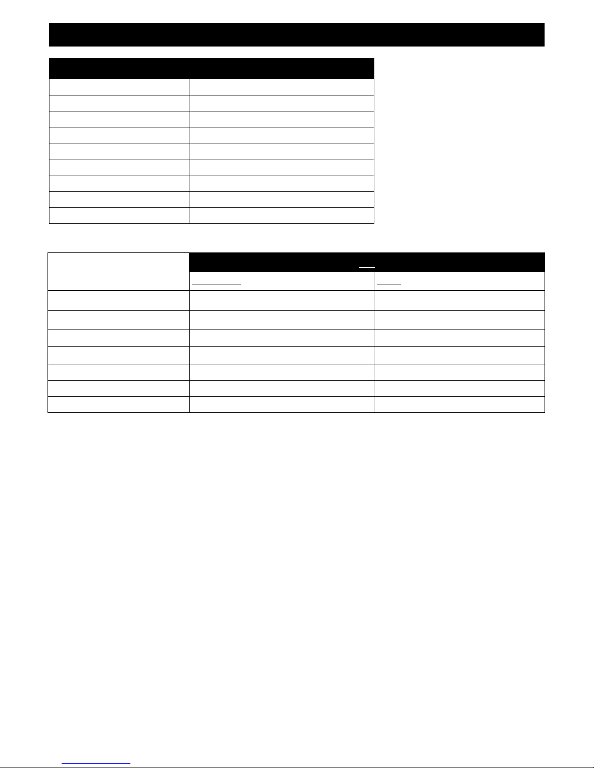
#911 COMPONENTS
911-770 Millivolt Control Board Assembly
700-203 Manual Gas Shut-off Valve
911-135 Burner Assembly
911-G900 Refractory Set
932-500A Log Package
700-08T Glass Assembly
815-CL1 Co-Linear Air Chute
911-028 Fan Kit (2)-75 CFM
900-085 4” Restrictor Plate
MINIMUM INLET GAS PRESSURE 5” WC (1.25 kPa) (7” WC (1.74 kPa) (recommended) 11” WC (2.74 kPa) (recommended)
MAXIMUM INLET GAS PRESSURE 10.5” WC (2.62 kPa) 13” WC (3.24 kPa)
MANIFOLD PRESSURE (HI) 3.5” WC (.87 kPa) 10” WC (2.49 kPa)
MANIFOLD PRESSURE (LO) 1.6” WC (.40 kPa) 6.4” WC (1.59 kPa)
ORIFICE SIZE #32 #50
INPUT BTU/hr. (kW) 36,500 BTU/hr (10.7 kW) 32,000 BTU/hr (9.38 kW)
MINIMUM INPUT BTU/hr. (kW) 27,500 BTU/hr (8.06 kW) 23,500 BTU/hr (6.89kW)
NATURAL GAS LP GAS
911
3
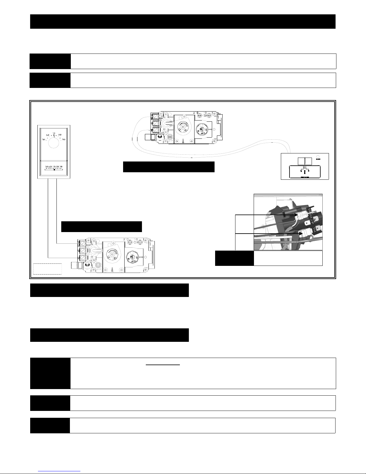
THERMOSTAT / WALL SWITCH / REMOTE
If desired, a thermostat (wireless style also available), wall switch, or remote control assembly may be used to turn fireplace OFF and ON.
Only ONE of these may be installed. Follow instructions included with chosen assembly.
NOTE
CAUTION
INSTALLATION OF THERMOSTAT OR WALL SWITCH SHOULD ONLY BE PERFORMED BY A QUALIFIED INSTALLER .
DO NOT CONNECT HIGH VOLTAGE (115V) WIRE TO THE GAS VALVE!
Remote Control Wiring Diagram
Thermostat Wiring Diagram
OPTIONAL
Figure 4a
Disconnect ON/OFF rocker switch
wires from back of gas valve.
WALL SWITCH / THERMOSTAT:
Run low-voltage (thermostat) wires from terminals on gas valve to desired location of wall switch or thermostat.
Attach appropriate connectors to wall switch / thermostat wires and connect to top and bottom terminals marked TH/TPTH on gas valve.
REMOTE CONTROL:
Follow instructions included with remote control.
If ON/OFF rocker switch wires are not disconnected, the ON/OFF rocker switch on millivolt board must be in OFF position for
IMPORTANT
NOTE
IMPORTANT The insulated cover included with remote control must be placed over remote receiver to prevent overheating.
proper operation of any of these components.
If rocker switch is ON, fireplace burner will operate until it is turned OFF by rocker switch. A wall switch, thermostat, or
remote control will not turn fireplace OFF when it has been turned ON by the rocker switch.
Fireplace must be turned ON and OFF by same method. For example: If fireplace is turned ON by remote control, it must be
turned OFF by remote control.
4
 Loading...