

kozy heat 56150 LAKEFIELD, 56520 BRECKENRIDGE Installation And Operation Manual
Quality Fireplaces for Life
INSTALLATION AND OPERATION MANUAL
INSTALLER: LEAVE THIS MANUAL WITH THE APPLIANCE.
CONSUMER: RETAIN THIS MANUAL FOR FUTURE REFERENCE.
DO NOT
DISCARD
FREE-STANDING
DIRECT VENT FIREPLACES
WARNING: This product must be installed by a licensed plumber or gas fitter when installed in the
commonwealth of Massachusetts.
This appliance may be installed in an aftermarket permanently located, manufactured (mobile) home, where not prohibited by lo cal codes.
A manufactured home (USA only) or mobile home OEM installation must conform with the Manufactured Home Construction and Safety Standard,
Title 24 CFR, Part 3280, or when such a standard is not applicable, the Standard for Manufactured Home Installations, ANSI/NCSBCS A225.1, or
Standard for Gas Equipped Recreational Vehicles and Mobile Housing, CSA Z240.4
WARNING: If the information in these instructions are not followed exactly, a fire or explosion may
result, causing property damage, personal injury or loss of life.
LAKEFIELD
Shown with optional brushed nickel
Prairie doors and stainless drop-in side
inserts.
BRECKENRIDGE
◙ Do not store or use gasoline or other flammable vapors and liquids in the vicinity of this or any other
appliance.
IF YOU SMELL GAS:
◙ Do not light any appliance.
◙ Do not touch any electrical switch: do not use any phone in your building.
◙ Immediately call gas supplier from a neighbors phone. Follow the gas supplier instructions.
◙ If you cannot reach your gas supplier, call the fire department.
◙ Installation and service must be performed by a qualified installer, service agency or the gas supplier.
This appliance is only for use with the type (s) of gas indicated on the rating plate. A conversion kit is supplied
with the appliance.
WARNING
HOT GLASS WILL CAUSE BURNS.
DO NOT TOUCH GLASS UNTIL COOLED.
NEVER ALLOW CHILDREN TO TOUCH GLASS.
www.kozyheat.com
January 2010
LKFBRK-R11
INTRODUCTION
Read this manual before installing or operating this appliance.
Please retain this owner‟s manual for future reference.
CONGRATULATIONS!
We welcome you as a new owner of a Kozy Heat gas fireplace. Kozy Heat
products are designed with superior components and materials and assembled by
trained craftsmen who take pride in their work. The burner and valve assembly are
100% test-fired and the complete fireplace is thoroughly inspected before packaging
to ensure that you receive a quality product. Our commitment to quality and
customer satisfaction have remained the same for over 30 years. We offer a
complete line of gas and wood fireplaces, unique cabinets and stylish accessories to
compliment any décor. Adding a fireplace is one of the best ways to increase the
value of your home and we are proud to offer a network of dealers throughout the
country to help make your experience everything you imagine. We pride ourselves in
being dedicated to not only function and reliability, but customer safety as well.
We offer our continual support and guidance to help you achieve the maximum
benefit and enjoyment from your Kozy Heat gas fireplace.
Jim Hussong Dudley Hussong
President Board Chairman
Homeowner Reference Information
We recommend that you record the following information about your fireplace.
Model Name:______________________________ Date purchased/installed:____________
Serial Number:____________________________ Location on fireplace:_______________
Dealership purchased from:__________________ Dealer Phone:_____________________
Notes:_____________________________________________________________________
__________________________________________________________________________
__________________________________________________________________________
PAGE 1
TABLE OF CONTENTS
INTRODUCTION
Introduction and Homeowner Reference Information 1
CONTENTS
Table of Contents 2
SAFETY INFORMATION
Safety Information 3
FEATURES
Features 4
COMMONWEALTH OF MASSACHUSETTS INFORMATION
Commonwealth of Massachusetts Information 5
SPECIFICATIONS
Fireplace Dimensions 6
Clearances 7
Components List 8
Placement Clearance Requirements 8
FRAMING
Vertical Terminations 9
Horizontal Terminations 9
GLASS FRAME ASSEMBLY
Remove Cast Door / Glass Frame Assembly 9
Install Cast Door / Glass Frame Assembly 9
OPTIONAL FAN INSTALLATION
Lakefield Optional Fan Installation 10
Breckenridge Optional Fan Installation 11
GAS LINE CONNECTION
Gas Line Connection 12
THERMOSTAT / WALL SWITCH / REMOTE
Thermostat / Wall Switch / Remote 13
VENTING
Approved Venting 14
Horizontal Vent System Clearances 14
Horizontal Terminations 14
Vertical Vent System Clearances 14
Vertical Terminations 14
Restrictor Requirements / Installation 15
Elbows 15
Min. / Max. Horizontal Venting Illustration 16
Min. / Max. Vertical Venting Illustration 16
Horizontal / Vertical Combination Chart 16
Termination Cap Location 17
Vent Termination Clearances (Vertical Cap Requirements) 18
LOG SET INSTALLATION
Log Set Installation 19
MILLIVOLT BOARD REMOVAL / INSTALLATION
Millivolt Board Removal 20
OPERATING INSTRUCTIONS
Valve and Pilot Assembly Components 21
Lighting and Shutdown Instructions 22-24
Pressure Testing 25
FINALIZING THE INSTALLATION
Flame Appearance 26
To Adjust Venturi 26
Restrictor Troubleshooting / Installation After Termination Completion 27
Seasonal Heat Dump 28
MAINTENANCE
Maintenance 29
TROUBLESHOOTING
Troubleshooting 30-32
REPLACEMENT PARTS LIST
Replacement Parts List 33
WARRANTY
Warranty 34-35
PAGE 2
SAFETY INFORMATION
This fireplace has been tested to and complies with ANSI Z21.88-2009·CSA 2.33-2009·CSA P.4.1-02 “VENTED GAS FIREPLACE
HEATERS” by PFS Corporation, Madison, Wisconsin. Installation must conform with local building codes or in the absence of local
building codes, with the National Fuel Gas Code, ANSIZ223.1/NFPA 54 - Current Edition, or the Natural or Propane Installation Code,
CSAB149.1
Installation and repair should be done only by a qualified service person. The appliance should be inspected by a
qualified service person before use. Annual inspection by a qualified service person is required to maintain warranty.
More frequent cleaning may be required due to excessive lint from carpeting, bedding materials, etc. It is imperative that
control compartments, burners and circulation air passageways of the appliance be kept clean.
If this appliance is installed directly on carpeting, tile or other combustible material other than wood flooring, the
appliance shall be installed on a metal or wood panel extending the full width and depth of the appliance.
Children and adults should be alerted to the hazards of high surface temperatures and should stay away to avoid burns
or clothing ignition.
Young children should be carefully supervised when they are in the same room as the appliance. Toddlers, young
children and others may be susceptible to accidental contact burns. A physical barrier is recommended if there are at
risk individuals in the house. To restrict access to a fireplace or stove, install an adjustable safety gate to keep toddlers ,
young children and other at risk individuals out of the room and away from hot surfaces.
Clothing or other flammable material should not be place on or near the appliance.
Adequate accessibility clearances for servicing and proper operation must be maintained.
This appliance must not share or be connected to a chimney flue serving any other appliance.
Keep area around the appliance clear of combustible materials, gasoline and other flammable vapor and liquids.
The flow of combustion and ventilation air must not be obstructed.
Due to high temperatures the appliance should be located out of traffic and away from furniture and draperies.
The glass front or any part removed for servicing the appliance must be replaced prior to operating the appliance. Work
should be done by a qualified service technician.
Clean glass only when cool and only with non-abrasive cleansers.
Do not operate this appliance with the glass/frame assembly removed, cracked or broken. The glass assembly,
Part #700-15T, shall only be replaced as a complete unit, as supplied by Hussong Mfg. Co., Inc. Replacement of the glass
assembly must only be performed by a licensed or qualified service person. DO NOT SUBSTITUTE MATERIALS.
Do not strike or slam glass assembly.
Any safety screen or guard removed for servicing the appliance must be replaced prior to operating the appliance.
Under no circumstances should any solid fuel (wood, coal, paper or cardboard etc.) be used in this appliance.
Keep burner and control compartment clean.
Do not use this fireplace if any part has been under water. Immediately call a qualified service technician to inspect this
appliance and to replace any part of the control system and any gas control which has been under water.
PAGE 3
FEATURES
STANDARD FEATURES
High efficiency
High quality lifetime glass
14” x 21” (356 mm x 533 mm)
Quick latch glass frame assembly
Seasonal heat dump baffle
Patented burner design
High - Low regulator
Flip-up control panel cover
Patented log design
Refractory brick lining
Minnesota Energy Code compliant to 50 pascals
OPTIONAL FEATURES
Automatic fan kit (2) - 75 CFM with variable speed control &
dashboard mount
Remote control or thermostat remote control
Remote control mounting bracket
Wall mount thermostat / wireless wall mount thermostat
Prairie design style screen doors in several finishes**
Black, rust or titanium finishes available for stove**
Prairie design frame with stainless steel drop-in side insets*
Prairie design frame for individual customizing**
Black cast, ivory, brown, or blue enamel finishes available*
Hearth pads in several shapes and sizes
Hearth tile kits in several colors
** Lakefield only
* Breckenridge only
SAFETY FEATURES
Each unit factory tested!
Tested by PFS Corporation
Sealed combustion chamber with standing pilot ignition
Removable millivolt board with 30-second delay pilot
Automatic pressure relief glass system
Requires no electricity to operate
(excluding fan)
Bedroom and mobile home approved
Canadian approved
WEIGHT
Lakefield (as packaged for shipment)
152 lbs. (69 kg)
Breckenridge (as packaged for shipment)
280 lbs. (127 kg.)
PAGE 4

COMMONWEALTH OF MASSACHUSETTS REQUIREMENTS
NOTE: The following requirements reference various Massachusetts
and national codes not contained in this manual.
For all sidewall horizontally vented gas fueled equipment installed in every dwelling, building or structure used in whole or in part for residential purposes,
including those owned or operated by the Commonwealth and where the side wall exhaust vent termination is less than (7) feet above finished grade in the
area of the venting, including but not limited to decks and porches, the following requirements shall be satisfied:
INSTALLATION OF CARBON MONOXIDE DETECTORS
At the time of installation of the side wall horizontally vented gas fueled equipment, the installing plumber or gas-fitter shall observe that a hard wired
carbon monoxide detector with an alarm and battery back-up is installed on the floor level where the gas equipment is to be installed. In addition, the
installing plumber or gas-fitter shall observe that a battery operated or hard wired carbon monoxide detector is installed on each additional level of
the dwelling, building or structure served by the side wall horizontal vented gas fueled equipment. It shall be the responsibility of the property owner
to secure the services of qualified licensed professionals for the installation of hard wired carbon monoxide detectors.
In the event that the side wall horizontally vented gas fueled equipment is installed in a crawl space or attic, the hard wired carbon monoxide detector with
alarm and battery back-up may be installed on the next adjacent floor level.
In the event that the requirements of this subdivision can not be met at the time of completion of installation, the owner shall have a period of thirty (30)
days to comply with the above requirements; provided, however, that during said thirty (30) day period, a battery operated carbon monoxide detector with
an alarm shall be installed.
APPROVED CARBON MONOXIDE DETECTORS
Each carbon monoxide detector as required in accordance with the above provisions shall comply with NFPA 720 and be ANSI/UL 2 034 listed and IAS
certified.
SIGNAGE
A metal or plastic identification plate shall be permanently mounted to the exterior of the building at a minimum of eight (8) feet above grade directly in
line with the exhaust vent terminal for the horizontally vented gas fueled heating appliance or equipment. The sign shall rea d, in print no less the one-half
inch (1/2”) in size, “GAS VENT DIRECTLY BELOW. KEEP CLEAR OF ALL OBSTRUCTIONS”.
INSPECTION
The state or local gas inspector of the side wall horizontally vented gas fueled equipment shall not approve the installation unless, upon inspection, the
inspector observes carbon monoxide detectors and signage installed in accordance with the provisions of 248 CMR 5.08 (2) (a) 1 through 4.
EXEMPTIONS
The following equipment is exempt from 248 CMR 5.08 (2) (a) 1 through 4:The equipment listed in Chapter 10 entitled “Equipment Not Required To Be
Vented” in the most current edition of NFPA 54 as adopted by the Board; and Product Approved side wall horizontally vented ga s fueled equipment
installed in a room or structure separate from the dwelling, building or structure used in whole or in part for residential purposes.
MANUFACTURER REQUIREMENTS - GAS EQUIPMENT VENTING SYSTEM PROVIDED
When the manufacturer of Product Approved side wall horizontally vented gas equipment provides a venting system design or venting system
components with the equipment, the instructions provided by the manufacturer for installation of the equipment and the venting system shall include:
Detailed instructions for the installation of the venting system design or the venting system components; and
A complete parts list for the venting system design or venting system.
MANUFACTURER REQUIREMENTS - GAS EQUIPMENT VENTING SYSTEM NOT PROVIDED
When the manufacturer of Product Approved side wall horizontally vented gas equipment does not provide the parts for venting the flue gases, but
identifies “special venting systems”, the following requirements shall be satisfied by the manufacturer:
The referenced “special venting systems” instructions shall be included with the appliance or equipment installation instructions and;
The “special venting systems” shall be Product Approved by the Board, and the instructions for that system shall include a parts list and
detailed installation instructions.
A copy of all installation instructions for all Product Approved side wall horizontally vented gas fueled equipment, all vent ing instructions, all parts lists
for venting instructions, and/or all venting design instructions shall remain with the appliance or equipment at the completion of the installation.
PAGE 5
SPECIFICATIONS
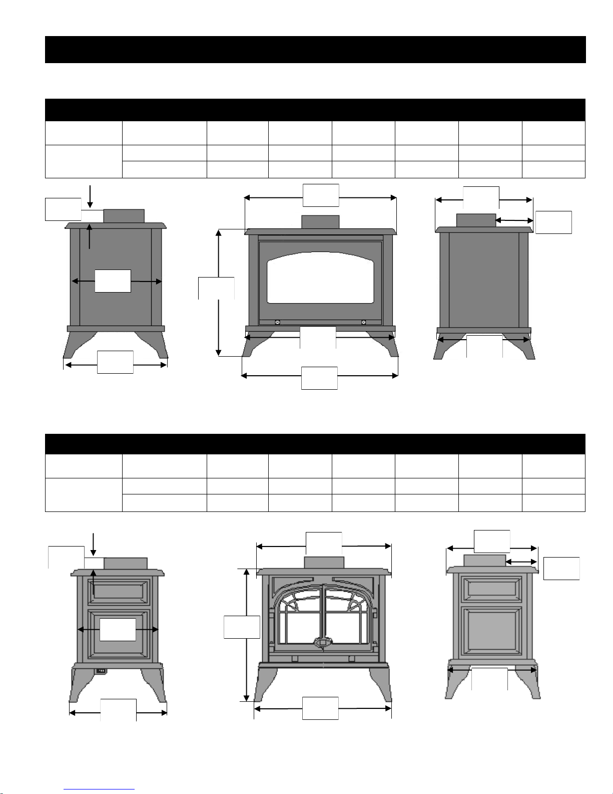
LAKEFIELD DIMENSIONS
DESCRIPTION Height Width Depth
(at leg base)
Depth
(at unit top)
Vent to unit back Unit top to vent top
FIREPLACE
DIMENSIONS
2-1/2”
(64 mm)
15”
(381 mm)
17-1/4”
(438 mm)
INCHES 27-3/4 27-1/2 17-1/4 16-1/2 4 2-1/2
MILLIMETERS 705 699 438 419 102 64
27-1/2”
(699 mm)
27-3/4”
(705 mm)
26-1/4”
(667 mm)
27-1/2”
(699 mm)
16-1/2”
(419 mm)
(102 mm)
15-7/8”
(403 mm)
4”
FIREPLACE
DIMENSIONS
2”
(51 mm)
15-7/8”
(403 mm)
18-1/4”
(464 mm)
BRECKENRIDGE DIMENSIONS
DESCRIPTION Height Width Depth
INCHES 28-1/4 27-5/8 18-1/4 18-7/8 4-1/4 2
MILLIMETERS 718 702 464 479 108 51
27-5/8”
(702 mm)
28-1/4”
(718 mm)
28-1/8”
(460 mm)
(at leg base)
Depth
(at unit top)
Vent to unit back Unit top to vent top
18-7/8”
(479 mm)
(108mm)
18-7/8”
(479 mm)
4-1/4”
PAGE 6
SPECIFICATIONS
NOTE: Other clearances apply. All clearances must be maintained.
WARNING: Fireplace must be placed directly on wood or non-combustible surface (not linoleum or carpet) extending e ntire depth and width of fireplace.
CLEARANCES
Unit* to sidewall: 7" (178 mm)
Unit* to back wall: 5" (127 mm)
Unit top to ceiling: 47" (1194 mm)
From flue vent: 1" (25 mm)
*Measurement is from top corner of fireplace.
47”
(1194 mm)
1”
(25 mm)
1”
(25 mm)
1”
(25 mm)
7”
(178 mm)
1”
(25 mm)
1”
(25 mm)
5”
(127 mm)
1”
(25 mm)
5”
(127 mm)
5”
(127 mm)
24-1/2”
(622 mm)
5”
(127 mm)
PAGE 7

SPECIFICATIONS
COMPONENTS LIST
(#LKF-770) - Millivolt Board Assembly with 18” Flexible Gas Line attached**
(#BRK-770) - Millivolt Board Assembly with 18” Flexible Gas Line attached*
(#700-203) - Manual Gas Shut-off Valve
(#LKF-G900) - Refractory Set
(#BRK-500) - Log Package
(#LKF-005) - Glass Valance
(#700-15T) - Glass with Gasket
(#OCK-S0A) - LP Conversion Kit
(#600-083) - Receptacle / Speed Control Assembly with (3) Wire Nuts
(#900-085) - 4” Restrictor Plate
** Lakefield only
* Breckenridge only
INSTALLATION OVERVIEW
NOTE: The qualified installer should follow the procedure best suited for the installation.
1. Determine stove location, allowing for vent installation.
2. Install hearth (if applicable).
3. Complete gas line installation.
4. Complete electrical hook-up. Install any standard or optional electrical components at this time.
5. Complete venting installation.
6. Secure fireplace to flooring through holes located in unit legs. Verify all clearances at this point.
7. Install logs.
8. Install optional decorative doors or other accessories.
9. Verify proper operation of fireplace and all components.
PLACEMENT CLEARANCE REQUIREMENTS
This fireplace must be installed on a level surface capable of supporting fireplace and venting.
Fireplace must be placed directly on wood or non-combustible surface (not linoleum or carpet) extending entire depth and width of
fireplace.
Due to high surface temperatures, fireplace should be located out of traffic and away from furniture and draperies.
This fireplace may be installed in a bedroom.
Please be aware of the large amount of heat this fireplace will produce when determining a location.
PAGE 8
FRAMING
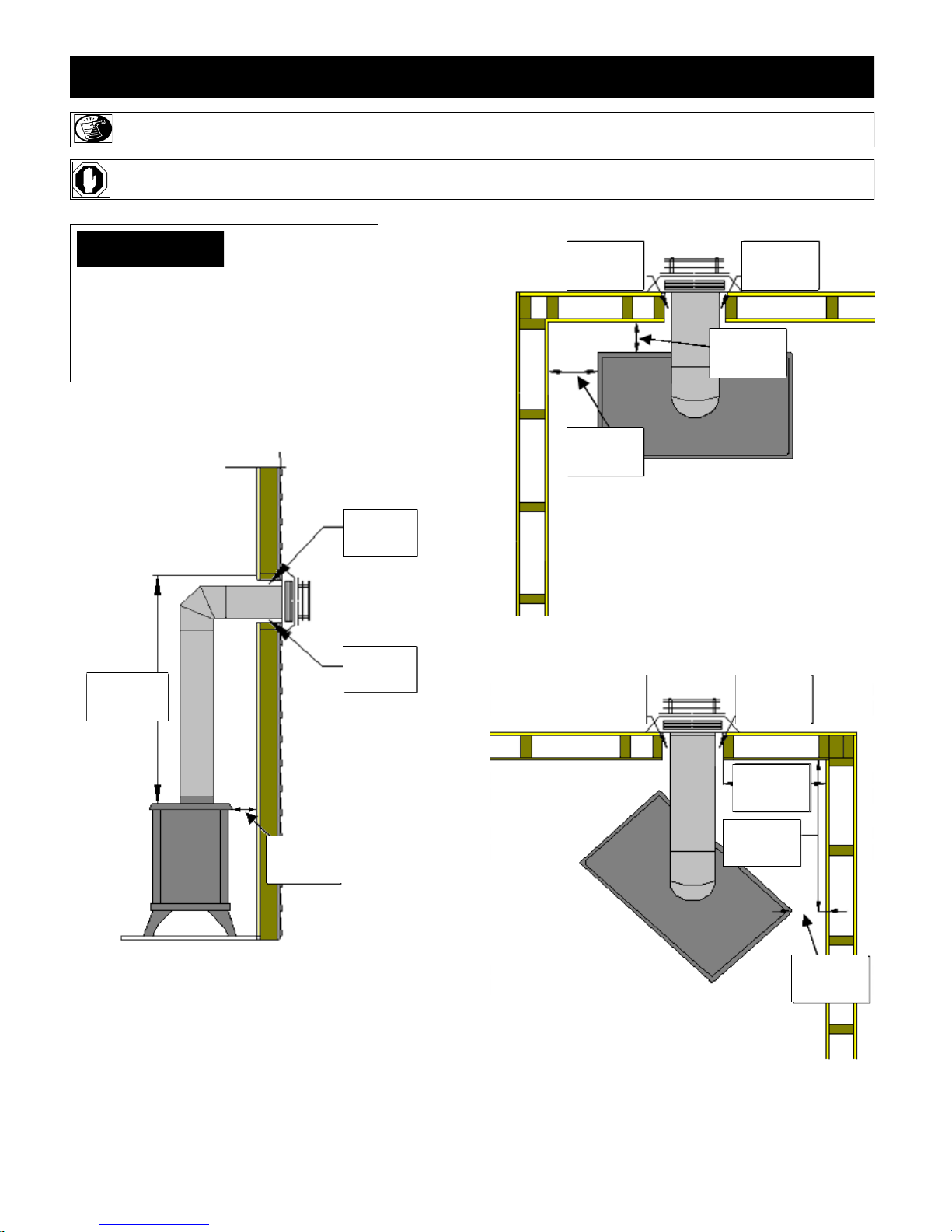
IMPORTANT: Vent cap location must be in compliance with guidelines on page #17
of this manual.
Refer to vent pipe manufacturer‟s
instructions for specific height (H)
and width (W) framing dimensions.
VERTICAL TERMINATIONS
Follow vent pipe manufacturer‟s installation instructions for vertical terminations. A
minimum 1” (25 mm) clearance on all sides of vertical vent pipe must be maintained.
HORIZONTAL TERMINATIONS
Follow vent pipe manufacturer‟s installation instructions for horizontal terminations.
Include required 1-1/2” (38 mm) top clearance (at wall pass-thru) and 1” (25 mm) sides
and bottom clearances for approved rigid vent systems.
IMPORTANT:
Minimum venting: 75” (1.905 m) from floor or hearth to top of vent pipe.
IMPORTANT: WALL PASS-THRU REQUIRED FOR ALL HORIZONTAL RUNS.
REFER TO VENT MANUFACTURER‟S TO DETERMINE WHICH
PASS-THRU WILL WORK BEST FOR YOUR APPLICATION AND
WALL THICKNESS.
75” (1.905 m) min.
to top of vent pipe
CAST DOOR / GLASS FRAME ASSEMBLY
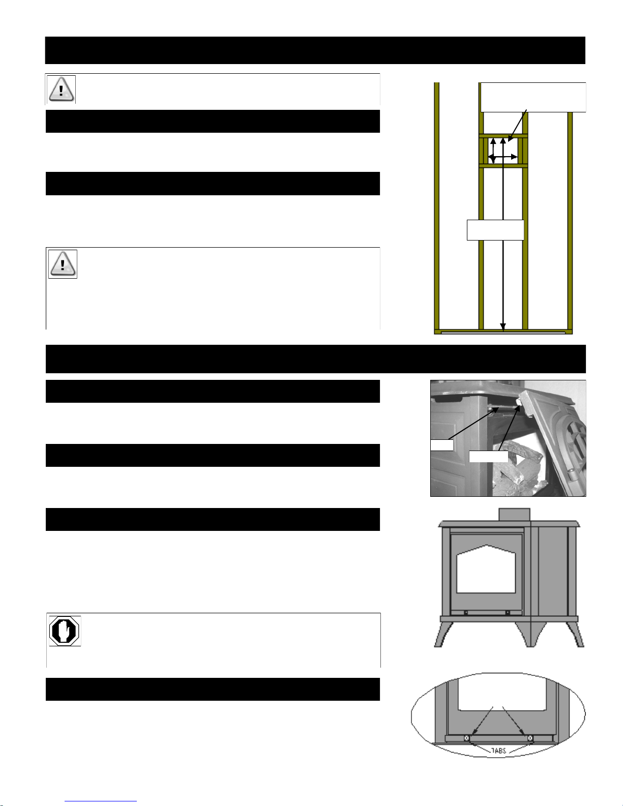
REMOVE CAST DOOR (Breckenridge only)
Pull bottom of door out and up while lifting up to disconnect latches from mounting rod
located behind assembly.
INSTALL CAST DOOR (Breckenridge only)
Lift door high enough to align latches above mounting rod, lowering slowly into
position.
REMOVE GLASS FRAME ASSEMBLY
A. Locate metal bar (glass latching mechanism) below glass frame.
B. To release glass assembly, pull latch mechanism knobs out, then immediately
down, securing metal bar onto stops.
C. Pull bottom of glass assembly out, lifting up and off tabs at top of firebox.
WARNING: DO NOT OPERATE THIS FIREPLACE WITH THE GLASS REMOVED,
CRACKED OR BROKEN. REPLACEMENT OF GLASS ASSEMBLY, #700-07T
SHOULD BE DONE BY A LICENSED OR QUALIFIED SERVICE PERSON.
WARNING: DO NOT REMOVE GLASS ASSEMBLY WHEN HOT!
INSTALL GLASS FRAME ASSEMBLY
ROD
LATCH
Pull knobs out and
down to release.
A. Place glass frame assembly top over tabs at top of firebox.
B. Pull bottom handles out and „up‟ to secure glass frame assembly bottom.
PAGE 9
LAKEFIELD OPTIONAL FAN KIT INSTALLATION
INSTALLATION OF THIS FAN SHOULD BE DONE ONLY BY A QUALIFIED INSTALLER
This optional #LKF-028 fan kit includes:
- Right & left fan assemblies - mounted - Fan cover plate
- Temperature control switch with magnet attached - (4) Flange nuts
- Speed Control Box with 8 ft. cord - (4) Phillips head screws (black)
WARNING: MAKE SURE HOUSEHOLD BREAKER IS SHUT OFF PRIOR TO WORKING ON ANY ELECTRICAL LINES.
WARNING: This appliance is equipped with a three-prong (grounding) plug for protection against shock hazard and should be plugged into a
properly grounded three-prong receptacle. Do not cut or remove grounding prong from plug.
NOTE: This appliance must be electrically grounded and connected in accordance with local codes, or in the absence of local codes, with the National
Electrical Code, ANSI/NFPA 70 Current Edition, or the Canadian electrical Code CSA C22.1.
will turn „ON‟ and „OFF‟ automatically as fireplace heats and cools. Adjust fan to desired speed while it is running.
NOTE: We recommend that an electrical outlet be installed near fireplace.
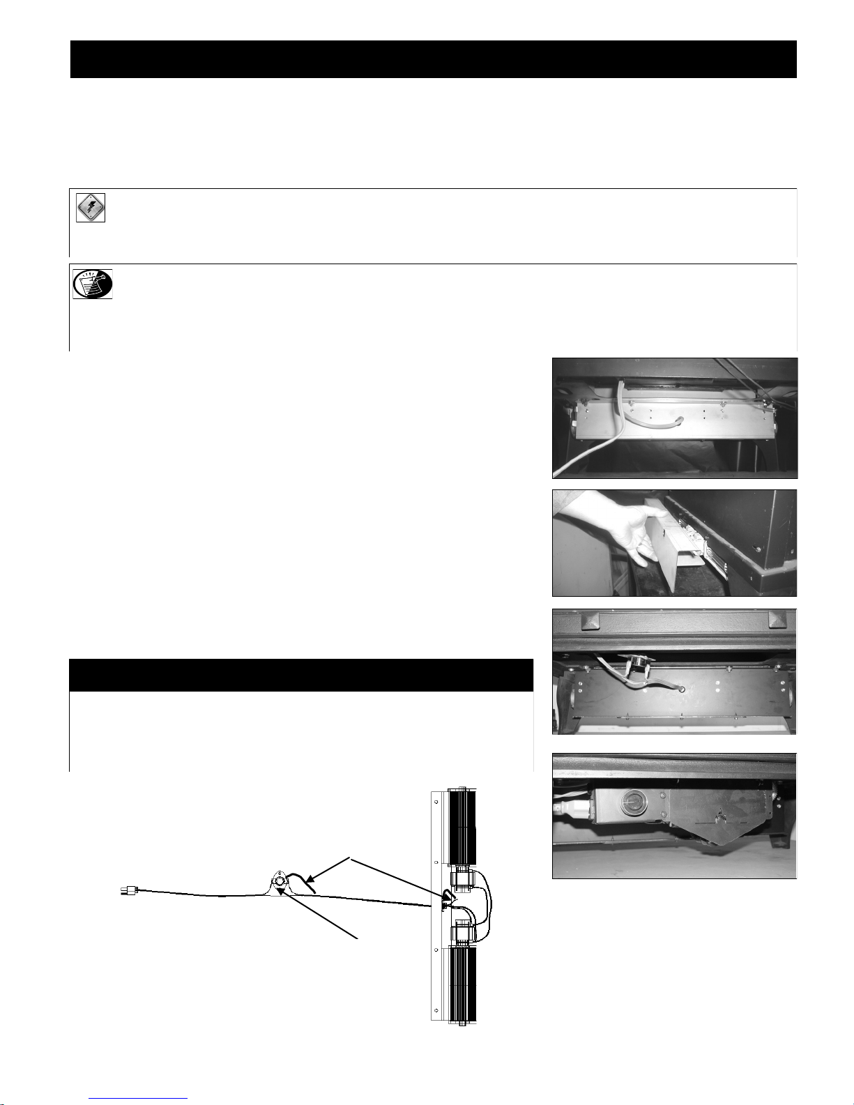
1. Locate (4) mounting studs underneath rear of fireplace.
2. Slide fan underneath fireplace, lift up, aligning (4) mount holes / slots in fan bracket to
3. Attach fan cover to back of fireplace by aligning holes in cover to holes at back of
4. Mount speed control box onto left side of gas valve bracket by aligning slots in box to
5. Place temperature control switch (magnet attached) onto bottom of firebox as close to
6. Plug fan cord into receptacle on speed control box.
7. Plug speed control box cord into a properly grounded three-prong receptacle.
8. Turn speed control counter-clockwise until it „clicks‟. This is the „OFF‟ position.
9. Turn speed control „ON‟ by turning knob clockwise past „click‟ - this is the highest
NOTE: This fan will not operate unless speed control has been turned „ON‟ and sufficient heat has been applied to temperatur e control switch. The fan
mounting studs under firebox. Secure with (4) nuts (included).
fireplace. Secure with remaining (2) screws.
holes in bracket. Secure with (2) black phillips head screws, included.
center as possible.
setting.
TEMPERATURE CONTROL SWITCH POSITION
Before adjusting temperature control switch, unplug 3-prong plug on fan cord from receptacle.
Adjust position of temperature control switch to a warmer location under firebox to turn fan „ON‟
sooner or move it to a cooler location under firebox to turn fan „ON‟ later. The fan will turn on when
sensor in temperature control switch reaches 110° F and will turn „OFF‟ when sensor reaches 90° F.
After adjustment, plug 3-prong plug on fan cord into receptacle.
Ground
Temperature Control Switch
PAGE 10
 Loading...