

kozy heat 56101 'Windom Installation And Operating Manual
MODEL: #56101 ‘WINDOM’
DIRECT VENT GAS FIREPLACE
INSTALLATION AND
OPERATING MANUAL
WARNING: If the information in these instructions
is not followed exactly, a fire or explosion may
result, causing property damage, personal injury
or loss of life.
♦ Do not store or use gasoline or other flammable
vapors and liquids in the vicinity of this or any
other appliance.
WHAT TO DO IF YOU SMELL GAS:
♦ Do not try to light any applia nce.
♦ Do not touch electrical switches; do not use the
phone in your building.
♦ Immediately call your gas supplier from a
neighbor’s phone. Follow your gas supplier’s
instructions.
♦ If you cannot reach your gas supplier, call the fire
department.
Installation & service must be performed by a qualified
installer, service agency, or the gas supplier.
US Patent Number 5,931,154
US Patent Number 6,004,493
Tested &
Listed By
C
OMNI-Test Laboratories, Inc.
US
Beaverton
Oregon USA
This appliance may be installed in an aftermarket
permanently located, manufactured (mobile) home,
where not prohibited by local codes. This appliance is
only for use with the type(s) of gas indicated on the
rating plate. This appliance is not convertible for use
with other gases, unless a certified kit is used.
IMPORTANT:
READ INSTRUCTIONS CAREFULLY BEFORE INSTALLATION. FAILURE
TO INSTALL THIS FIREPLACE CORRECTLY CAN CAUSE SERIOUS
STRUCTURAL AND FIRE HAZARDS AND MAY VOID YOUR WARRANTY.
www.kozyheat.com
March 2008

COMMONWEALTH OF MASSACHUSETTS
NOTE: The following requirements reference various Massachusetts and national codes not contained in this document.
REQUIREMENTS FOR THE COMMONWEALTH OF MASSACHUSETTS
For all side wall horizontally vented gas fueled equipment installed in every dwelling, building or structure used in whole or in part for
residential purposes, including those owned or operated by the Commonwealth and where the side wall exhaust vent termination is less than
seven (7) feet above finished grade in the area of the venting, including but not limited to decks and porches, the following requirements shall
be satisfied:
INSTALLATION OF CARBON MONOXIDE DETECTORS
At the time of installation of the side wall horizontal vented gas fueled equipment, the installing plumber or gas fitter shall observe that a hard
wired carbon monoxide detector with an alarm and battery bak-up is installed on the floor where the gas equipment is to be installed. In
addition, the installing plumber or gas fitter shall observe that a battery operated or hard wired carbon monoxide detector with an alarm is
installed on each additional level of the dwelling, building or structure served by the side wall horizontally vented gas fueled equipment. It
shall be the responsibility of the property owner to secure the services of qualified licensed professionals for the installation of hard wired
carbon monoxide detectors.
In the event that the side wall horizontally vented gas fueled equipment is installed a crawl space or an attic, the hard wired carbon monoxide
detector with alarm and battery back-up may be installed on the next adjacent floor level.
In the event that the requirements of the subdivision can not be met at the time of installation, the owner shall have a period of thirt y (30)
days to comply with the above requirements; provided, however, that during said thirty (30) day period, a battery op erated carbon m onoxide
detector with an alarm shall be installed.
APPROVED CARBON MONOXIDE DETECTORS
Each carbon monoxide detector as required in accordance with the above provisions shall comply with NFPA 720 and be ANSI/UL 2034
listed and IAS certified.
SIGNAGE
A metal or plastic identification plate shall be permanently mounted to the exterior of the building at a minimum height of eight (8) feet above
grade directly in line with the exhaust vent terminal for the horizontally vented gas fueled heating appliance or equipment. The sign shall
read, in print size no less than (½) inch in size, “GAS VENT DIRECTLY BELOW. KEEP CLEAR OF ALL OBSTRUCTIONS”.
INSPECTION
The state of local gas inspector of the side wall horizontally vented gas fueled equipment shall not approve the installation unless, upon
inspection, the inspector observes carbon
monoxide detectors and signage installed in accordance with the provisions of 248 CMR 5.08 (2) (a) 1 through 4.
EXEMPTIONS
The following equipment is exempt from 248 CMR 5.08 (2) (a) 1 through 4.
• The equipment listed in Chapter 10 entitled “Equipment Not Required To Be Vented” in the most current edition of NFPA 54 as adopted
by the Board; and
• Product Approved side wall horizontally vented gas fueled equipment installed in a room or structure separated from the dwelling,
building or structure used in whole or in part for residential purposes.
MANUFACTURER REQUIREMENTS
GAS EQUIPMENT VENTING SYSTEM PROVIDED
When the manufacturer of Product Approved side wall horizontally vented gas equipment provides a venting system design or venting
system components with the equipment, the instructions provided by the manufacturer for installation of the equipment and the venting
system shall include:
• Detailed instructions for the installation of the venting system design or the venting system components; and
• A complete parts list for the venting system design or venting system.
GAS EQUIPMENT VENTING NOT
When the manufacturer of Product Approved side wall horizontally vented gas equipment provides a venting system design or venting
system components with the equipment, the instructions provided by the manufacturer for installation of the equipment and the venting
system shall include:
• The referenced “special venting system” instructions shall be included with the appliance or equipment installation instructions; and
• The “special venting systems” shall be Product Approved by the Board, and the instructions for that system shall include a parts list and
detailed installation instructions.
A copy of all installation instructions for all Product Approved side wall horizontally vented gas fueled equipment, all venting instructions, all
parts lists for venting instructions, and/or all venting design instructions shall remain with the appliance or equipment at the completion of the
installation.
• Installation and repair must be done by a plumber or gas fitter licensed in the Commonwealth of Massachusetts.
• The flexible gas line connector used shall not exceed 36 inches (92 centimeters) in length.
• The individual manual shut-off must be a T-handle type.
PROVIDED

INDEX
DESCRIPTION PAGE
SAFETY REQUIREMENTS / SPECIFICATIONS ……….. ................................................................. 2-3
MINIMUM CLEARANCES …………………………………. .................................................................... 3
TYPICAL INSTALLATION OPTIONS …………………………………. ............................................... 3-4
VENTING REQUIREMENTS …………………………………. ............................................................. 5-8
MINIMUM / MAXIMUM VENTING REQUIREMENTS…………. ............ 5-6
HORIZONTAL VENTING …………………………………. ......................... 7
VERTICAL VENTING …………………………………. ............................... 8
POSITION THE UNIT …………………………………. ...................................................................... 9-10
VENT SYSTEM FRAMING …………………………………. ....................... 9
ROUGH-IN DIMENSIONS …………………………………. ...................... 10
REMOVE THE GLASS ASSEMBLY …………………………………. .................................................. 11
DIRECT VENT CHIMNEY INSTALLATION …………………………………. ....................................... 11
FAN INSTALLATION …………………………………. .................................................................... 12-13
GAS LINE SPECIFICATIONS …………………………………. ....................................................... 14-15
SECURE THE MILLIVOLT BOARD …………………………………. ................................................... 15
LOG INSTALLATION …………………………………. ......................................................................... 16
THERMOSTAT - WALL SWITCH - REMOTE CONTROL INSTALLATION …………………………. . 17
COMPLETE THE INSTALLATION …………………………………. ..................................................... 18
LIGHTING & SHUTDOWN …………………………………. ............................................................ 19-20
MANIFOLD & INCOMING PRESSURE CHECK PROCEDURES …………………………………. ..... 21
CLEANING & MAINTENANCE REQUIREMENTS …………………………………. ............................ 22
MILLIVOLT BOARD REMOVAL / INSTALLATION …………………………………. ...................... 23-24
TROUBLE SHOOTING …………………………………. .................................................................. 25-26
REPLACEMENT PARTS LISTS ………………………………….......................................................... 27
WARRANTY POLICY …………………………………. .................................................................... 28-29
Page 1
IMPORTANT:
5/8
3
3
READ THIS MANUAL BEFORE INSTALLING AND USING THIS FIREPLACE
MODEL #56101 ‘WINDOM’ DIRECT VENT GAS FIREPLACE
This fireplace has been tested to and complies with ANSI Z21.88a-2007
FIREPLACE HEATERS” by OMNI-Test Laboratories, Beaverton, OR. Installation must conform with local
building codes or in the absence of local building codes, with the National Fuel Gas Code, ANSI Z223.1, NFPA
54 - Current Edition.
S
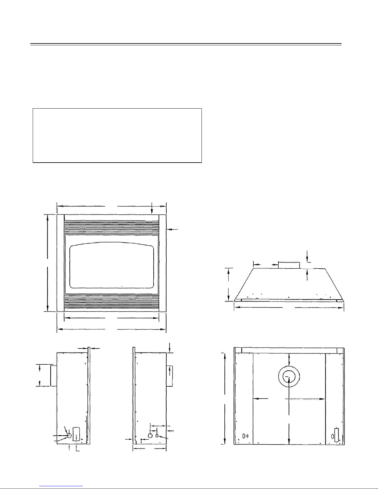
PECIFICATIONS
Height (front): . . . . . . . 32"
Height (back): . . . . . . . . 30 1/8"
Front width: . . . . . . . . . . 36"
Back width: . . . . . . . . . . 23 3/8"
Depth: . . . . . . . . . . . . . . 11"
Flue size: 4" exhaust, 6
" combustion air intake
PASS-THRU WALL THICKNESS: The Dura-Vent DV-GS 4" x 6 5/8" wall thimble, (Dura-Vent Part #942 / Kozy
Heat Part #D942) is designed for a minimum wall thickness of 4" and maximum wall thickness of 7 ½". The
Ameri-Vent wall thimble, (part #4DWT), is designed for a minimum wall thickness of 4 ½" and maximum wall
thickness of 8 ½".
V CSA 2.33a-2007 “VENTED GAS
6 7/
32"
"
8
36"
31"
36"
/4"
2"
2 3/
"
8
FIGURE 1
3
8
/
"
8
2"
11"
36"
4 1/4"
4 1/4"
Ø11/2"
4 3/4"
Gas Line
Access
1 1/
"
2
/4"
8
2 3/4"
11"
5 1/4"
3 5/8"
Ø3/4"
Page 2
30 1/
23 3/
"
"
8
8
22 3/
"
8
WARNING: This Product Must Be Installed By A
1
"
Cl
id
1
"
Cl
id
1
½
"
Cl
t
Licensed Plumber Or Gas Fitter When Installed
Within The Commonwealth of Massachusetts.
WARNING: Do not use this fireplace if any part has
been under water. Immediately call a qualified
service technician to inspect this appliance and to
replace any part of the control system and any gas
control which has been under water.
CONSULT YOUR LOCAL OR NATIONAL INSTALLATION
CODES TO ASSURE THAT ADEQUATE COMBUSTION
AND VENTILATION AIR IS AVAILABLE.
CLEARANCES - Minimum clearance to combustible:
From unit sides & back: 0"
From unit top stand-off: 0"
To flooring: 0"
From Vent Pipe:
Horizontal Runs:
Top: 1 ½" at wall pass-thru
Bottom & Sides: 1"
Vertical Runs:
All sides: 1"
From unit side to adjacent sidewall: 0"
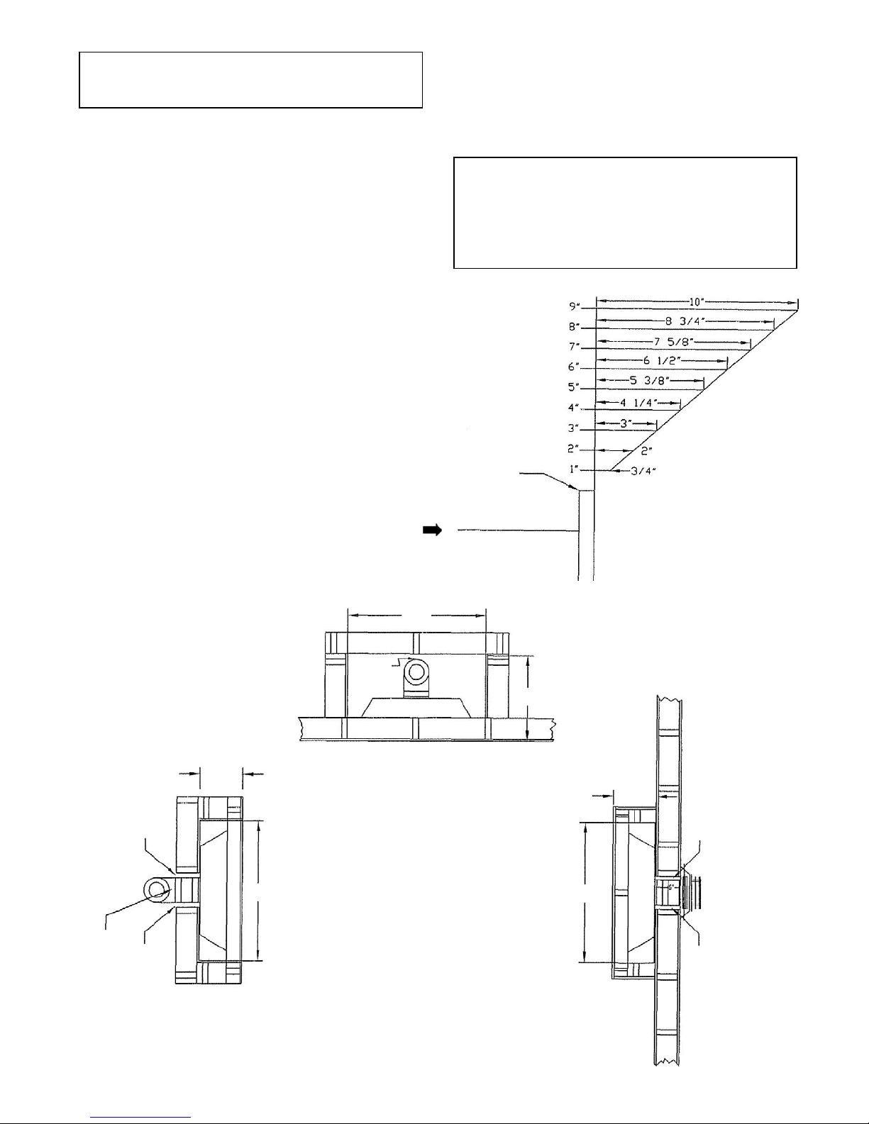
From top of unit to 10" mantel*: 9"
*See chart for additional mantel requirements
TYPICAL INSTALLATION OPTIONS:
36 ½"
WARNING:
DO NOT REPLACE THIS BURNER UNIT WITH ANY
OTHER SIZED BURNER. REPLACEMENT WITH AN
UNAUTHORIZED BURNER CAN RESULT IN
TEMPERATURES EXCEEDING THE LIMITS FOR THIS
UNIT, AND VOID YOUR WARRANTY.
IMPORTANT: NON-COMBUSTIBLE FACING MATERIAL
MAY BE APPLIED OVER THE FACE. TO PREVENT
THE FACING MATERIAL FROM CRACKING AND
FALLING OFF DUE TO EXPANSION OF THE FACE
WHEN HEATED, DO NOT ATTACH FACING MATERIAL
DIRECTLY TO THE FACE OF THE UNIT. DO NOT
MANTEL PROJECTION
HEIGHT FROM TOP OF FACE
TOP OF FACE
FIGURE 2A
sides & bottom
1" Clearance
11 ¼"
1"
Clearance
Model #56101 WINDOM
22 3/8"
earance - s
11 ¼"
es
NOTE:
1/4″ expansion space included in dimensions.
1/2″ wall materials included in dimensions
36 ½"
1" Clearance
sides & bottom
earance -
op
* Refer to vent manufacturer's specifications.
where applicable.
36 ½"
earance - s
es
Page 3
TYPICAL CORNER INSTALLATION:
MODEL #56101 'WINDOM'
MINIMUM DIMENSIONS - CORNER INSTALLATION
FIGURE 2B
1" Clearance at sides*
2
5
38
/8"
1" Clearance at sides*
1"
1
/4"
54 3/4"
KOZY HEAT CORNER CABINET INSTALLATION:
MODEL #56101 'WINDOM'
CORNER CABINET DIMENSIONS
"
1 Clearance at sides
32
21/4"
5
/8"
1"
5 1/2"
NOTE:
1" CLEARANCE FROM VENT SYSTEM
FRAMING TO FINISHED WALL REQUIRED.
2 1/4" FROM VENT PIPE TO FINISHED
WALL REQUIRED.
1" Clearance at sides
38 3/8"
IMPORTANT: DIMENSIONS INCLUDE 1/2" WALL MATERIAL.
TO DETERMINE FRAMING DIMENSIONS,
SUBTRACT THICKNESS OF WALL MATERIALS.
1" CLEARANCE FROM VENT SYSTEM FRAMING
TO FINISHED WALL REQUIRED.
2 1/4" FROM VENT PIPE TO FINISHED WALL
REQUIRED.
FIGURE 2C
MODEL #56101 'WINDOM'
POSITION FOR CORNER CABINET
1" Clearance at sides 1" Clearance at sides
1"
21/4"
32"
1
/4"
5
37
3
/4"
Page 4
VENTING REQUIREMENTS
p
V
THIS MODEL IS APPROVED FOR USE WITH SIMPSON DURA-VENT GS CHIMNEY SYSTEM 4" X 6 5/8"
AND AMERI-VENT DIRECT VENT SYSTEM 4" X 6 5/8" FOR HORIZONTAL AND VERTICAL TERMINATIONS.
IMPORTANT: This model is manufactured with the appropriate adaptor for proper connection of EITHER the
Contact your dealer for the appropriate vent kit and components part numbers for the chimney system you are
using.
Refer to the vent manufacturer's installation manual for complete installation instructions. Installation must
conform with the venting requirements & restrictions as outlined in this manual.
IMPORTANT: Consult the local and national installation codes to assure that adequate combustion and
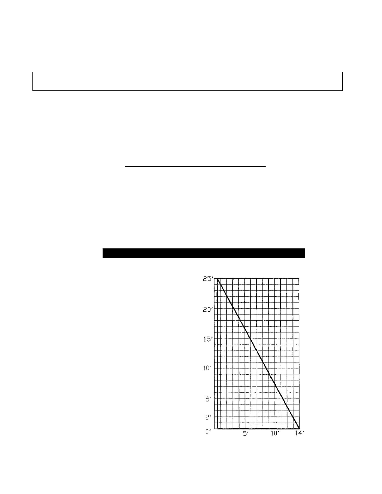
MINIMUM / MAXIMUM VENTING REQUIREMENTS:
Minimum vertical rise / maximum horizontal run: 0" / 14 ft.
Maximum vertical rise: 25 ft. - (requires 90° elbow to vertically position the chimney system).
Minimum horizontal vent run: 6"
Maximum horizontal run: 14 ft. (1/4" incline per horizontal foot must be maintained.)
Elbows: (1) 90-degree elbow is included within the maximum vent runs. Each additional elbow reduces the
maximum horizontal by 3'.
EXAMPLES OF CHART CONFIGURATIONS:
A vertical rise of 8 ft. may run horizontally a
maximum 9 ft. 7 in.
Vertical terminations require a 90° elbow to
vertically position the chimney.
Horizontal runs within the vertical configuration
reduces the maximum vertical run.
son Dura-Vent DV-GS Chimney System OR Ameri-Vent Direct Vent System.
Sim
ventilation air is available.
HORIZONTAL & VERTICAL VENTING CHART
ertical Rise
Horizontal Run
Page 5

TERMINATION VENT CAP LOCATION
This gas appliance must not be connected to a chimney flue serving another type of appliance.
GENERAL:
1. Terminations against vinyl siding must use a vinyl siding protector. Follow instructions included.
2. DO NOT RECESS TERMINATION KIT INTO OUTSIDE BUILDING MATERIALS - i.e.: brick, stone, siding,
etc. If necessary, extend framing so that termination kit will be exposed once building materials are
installed.
3. Vent termination must not be located where it will become plugged by snow or other material. The flow of
combustion and ventilation air must be not obstructed.
LOCATION CLEARANCES:
1. Above grade, veranda, porch, deck, balcony - 12". (A)
2. Operable window - 12". (B)
3. Permanently closed window* - 12" (recommended to prevent condensation on window). (C)
4. Ventilated soffit* - 24". (D)
5. Unventilated soffit* - 12". (E)
6. Outside / inside co rner* - 12". (F)
7. Meter / Regulator: not to be installed above within 3 ft. horizontally from the center line of the regulator.
8. Service regulator vent outlet - 3 ft. radius.
9. Electrical box - 3 ft. (G) DO NOT INSTALL ABOVE AN ELECTRICAL BOX!
10. Non-mechanical air supply inlet to building - 12".
11. Combustion air inlet to any other appliance - 12".
12. Mechanical air supply inlet. - 6 ft. (H)
13. Above furnace exhaust or inlet - 12".
14. Above paved side-walk or paved driveway located on public property - 7 ft.*(I)
15. Under veranda, porch, deck, or balcony (must be fully opened on a min. of 2 sides) - 12". (J)
16. Between two horizontal terminations - 12".
17. Between two vertical terminations - 12". (K) - Note: May be the same height.
* A vent cannot be located directly above a side-walk or paved driveway that is located between two
single family welling and serves both dwellings.
FIGURE 3
DENOTES WHERE INSTALLATION NOT ALLOWED
(1) OPERABLE WINDOW
(2) PERMANENTLY CLOSED WINDOW
* CHECK LOCAL & STATE BUILDING CODES FOR ADDITIONAL REQUIREMENTS AND/OR RESTRICTIONS.
Page 6
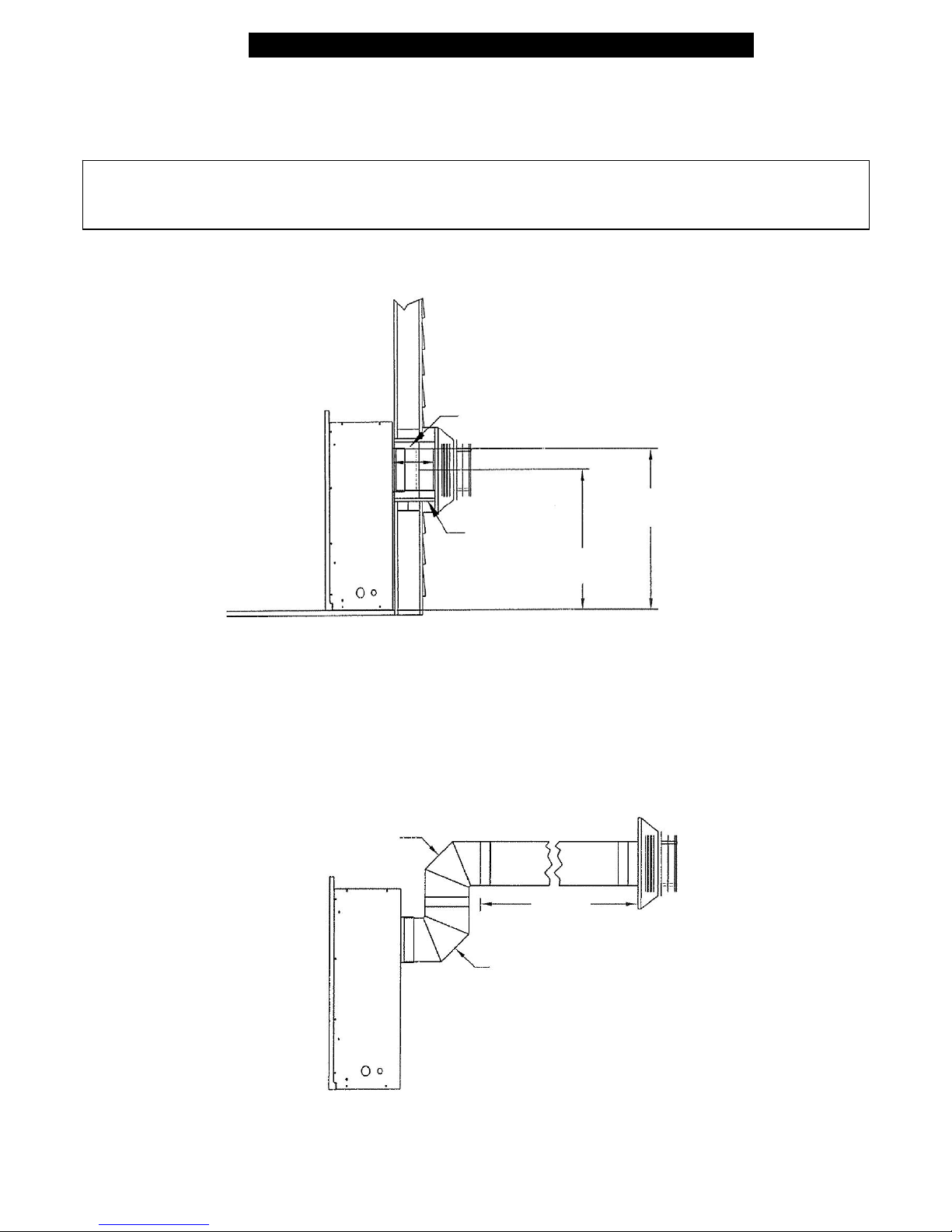
TYPICAL HORIZONTAL VENTING CONFIGURATIONS
The following are typical horizontal venting configurations which may be used. This generally will be determined
by location of the fireplace and how the fireplace will be finished on the interior. IMPORTANT: 1/4" INCLINE
PER HORIZONTAL FOOT MUST BE MAINTAINED.
IMPORTANT: PASS-THRU WALL THICKNESS:
Dura-Vent DV-GS 4" x 6 5/8" wall thimble: Minimum wall thickness of 4" / Maximum wall thickness of 7 ½".
Ameri-Vent Direct Vent system wall thimble: Minimum wall thickness of 4 ½" / Maximum wall thickness of 8 ½ ".
1. DIRECT-THRU-THE-WALL: Figure 4A - Attach a minimum 6" section pipe onto the fireplace followed by the
horizontal termination cap. Maximum horizontal run: 14 ft. (1/4" incline for each horizontal foot of chimney
must be maintained.)
6"
FIGURE 4A
2. HORIZONTAL RUNS USING 2 - 90 ELBOWS: Figure 4B - Attach 90 elbow onto the o o fireplace to
vertically position the chimney, followed by another 90o elbow to horizontally position the chimney, then a
minimum 6" / maximum 14 ft. horizontal run (1/4" incline for each horizontal foot of chimney must be
maintained.) WORKS WELL FOR CORNER INSTALLATIONS - See page 4.
Venting figuration shown in figure 2C when using the Kozy Heat Corner cabinet: (2) 90o elbows directly off
the collars on the fireplace and a 6" - 9" section (depending on wall thickness) to exit through the wall. See
figure 4C, page 8.
90° ELBOW
FIGURE 4B
1 ½" CLEARANCE AT THE TOP
FOR WALL PASS-THRU
26" TO TOP OF
VENT PIPE
WALL THIMBLE
223/8" TO CENTER
OF VENT PIPE
14 FT.
MAXIMUM
90° ELBOW
Page 7
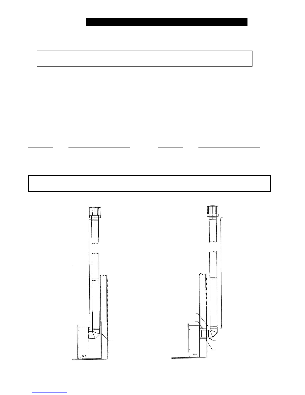
V
ERTICAL VENTING CONFIGURATIONS
pp
MAXIMUM VERTICAL RISE* AFTER FIRST ELBOW: 25 FT.
IMPORTANT: Horizontal runs within a vertical termination reduces the maximum vertical
*Note: Maximum vertical rise includes the first elbow to vertically position the chimney.
Elbows: (1) included to vertically position the chimney. Each additional elbow reduces the maximum horizontal
run by 3 ft..
MINIMUM VENT SYSTEM CLEARANCES FOR VERTICAL TERMINATIONS: 1" ALL SIDES. Refer to vent
manufacturer’s installation manual for specific information.
WHEN VERTICALLY TERMINATING, THE MINIMUM CHIMNEY HEIGHT ABOVE THE ROOF LINE IS
DETERMINED BY THE FOLLOWING CHART:
Roof Pitch Minimum Chimney Height Roof Pitch Minimum Chimney Height
Flat to 6/12 1 ft. 13/12 to 16/12 6 ft.
6/12 to 9/12 2 ft. 17/12 to 21/12 8 ft.
10/12 to 12/12 4 ft.
height allowed. Refer to the chart on page #5.
CAUTION: This gas appliance must not be connected to or joined with any chimney flue serving any
other a
liance.
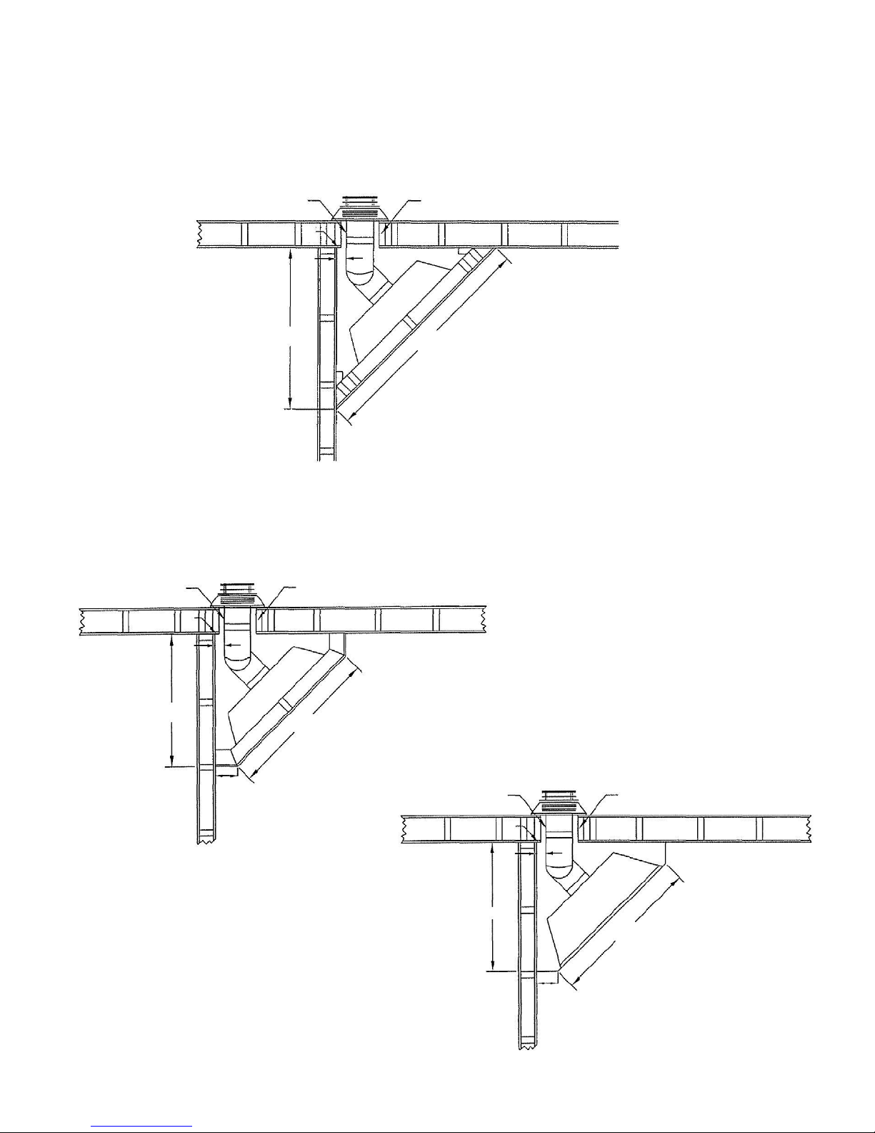
FIGURE 4C
MAX
25 FT.
25 Ft. Vertical Termination Requirements:
MAX
25 FT.
90° Elbow at start to vertically position
the chimney.
Horizontal runs within a vertical
termination reduces the maximum vertical
height allowed.
3" CLEARANCE
1 1/2" CLEARANCE AT TOP
FOR WALL PASS-THRU
1" CLEARANCE
Page 8
3" SECTION MAX. HORIZONTAL RUN FOR 25 FT.
VERTICAL RISE
WALL THIMBLE
 Loading...