

kozy heat 55801 Operating Manual
INSTALLATION & OPERATING MANUAL
MODEL #55801 ‘Duluth’
Free-Standing Direct Vent
Fireplace
U.S. Patent Numbers 5,931,154 & 6,004,493
WARNING: If the information in these instructions
is not followed exactly, a fire or explosion may
result, causing property damage, personal injury
or loss of life.
permanently located, manufactured home or mobile
home, where not prohibited by local codes. This
appliance is only for use with the type(s) of gas
indicated on the rating plate. This appliance is not
convertible for use with other gases, unless a
certified kit is used.
S Do not store or use gasoline or other
flammable vapors and liquids in the vicinity of
this or any other appliance.
WHAT TO DO IF YOU SMELL GAS:
‚ Do not try to light any appliance.
‚ Do not touch electrical switches; do not use
the phone in your building.
‚ Immediately call your gas supplier from a
neighbor’s phone. Follow your gas supplier’s
instructions.
‚ If you cannot reach your gas supplier, call the
fire department.
S Installation and service must be performed by
a qualified installer, service agency or the gas
supplier.
This appliance may be installed in an aftermarket
IMPORTANT:
READ INSTRUCTIONS CAREFULLY BEFORE
INSTALLATION. FAILURE TO INSTALL THIS FIREPLACE
CORRECTLY CAN CAUSE SERIOUS STRUCTURAL AND
FIRE HAZARDS AND MAY VOID YOUR WARRANTY.
July 2006
www.kozyheat.com

INDEX
DESCRIPTION PAGE
Safety Requirements / Specifications............................................. Front cover, 1-2
Clearances.............................................................................. 2-3
Venting Guidelines....................................................................... 3-7
Fan Installation (Optional) ................................................................. 8-9
Position the Unit....................................................................... 10-11
Chimney Framing Dimensions ..............................................................11
Set the Unit into Position...................................................................11
Removing the Arched Glass Assembly ......................................11
Install the Chimney.......................................................11
Gas Line Installation Requirements - Minimum/Maximum Pressures ...............................12
Millivolt Board Removal / Installation ...................................................... 13-14
Log Installation ........................................................................... 15
Thermostat - Remote Control - Wall Switch Installation ..........................................16
Completing the Installation:
Initial Lighting of Appliance ...............................................17
Seasonal Heat Dump Adjustment ...........................................17
Replace the Glass ........................................................17
Lighting & Shutdown Procedures......................................................... 18-19
Manifold (outgoing) & Inlet (incoming) Pressure Check Procedures ................................ 20
Maintenance Requirements.................................................................21
Troubleshooting ....................................................................... 22-23
Replacement Parts ........................................................................24
Warranty Policy........................................................................ 25-26
MODEL: #55801 ‘DULUTH’
FREESTANDING DIRECT VENT FIREPLACE
INSTALLATION & OPERATING INSTRUCTIONS
IMPORTANT:
READ THIS MANUAL BEFORE INSTALLING AND USING THIS FIREPLACE.
This fireplace has been tested to and complies with ANSI Z21.88CSA 2.33-M2002 “VENTED GAS
FIREPLACE HEATERS” by OMNI-Test Laboratories, Beaverton, Oregon for U.S. installations only.
Installation must conform with local building codes or in the absence of local building codes, with the
National Fuel Gas Code, ANSI Z223.1, NFPA 54 - Current Edition or the Natural or Propane Installation
Code, CSA B149.1.
COMMONWEALTH OF MASSACHUSETTS
INSTALLATIONS:
WARNING: This Product Must Be Installed By
A Licensed Plumber Or Gas Fitter When
Installed Within The Commonwealth of
Massachusetts.
IMPORTANT: Installation of a CO detector is
required in the fireplace room.
WARNING: Do not use this fireplace if
any part has been under water.
Immediately call a qualified service
technician to inspect this appliance and
to replace any part of the control
system and any gas control which has
been under water.
CONSULT YOUR LOCAL OR NATIONAL
INSTALLATION CODES TO ASSURE
THAT ADEQUATE COMBUSTION AND
VENTILATION AIR IS AVAILABLE.
WARNING: DO NOT REPLACE THIS BURNER UNIT WITH ANY OTHER SIZED BURNER.
REPLACEMENT WITH AN UNAUTHORIZED BURNER CAN RESULT IN
TEMPERATURES EXCEEDING THE LIMITS FOR THIS UNIT, AND VOID
YOUR WARRANTY
.
Page 1
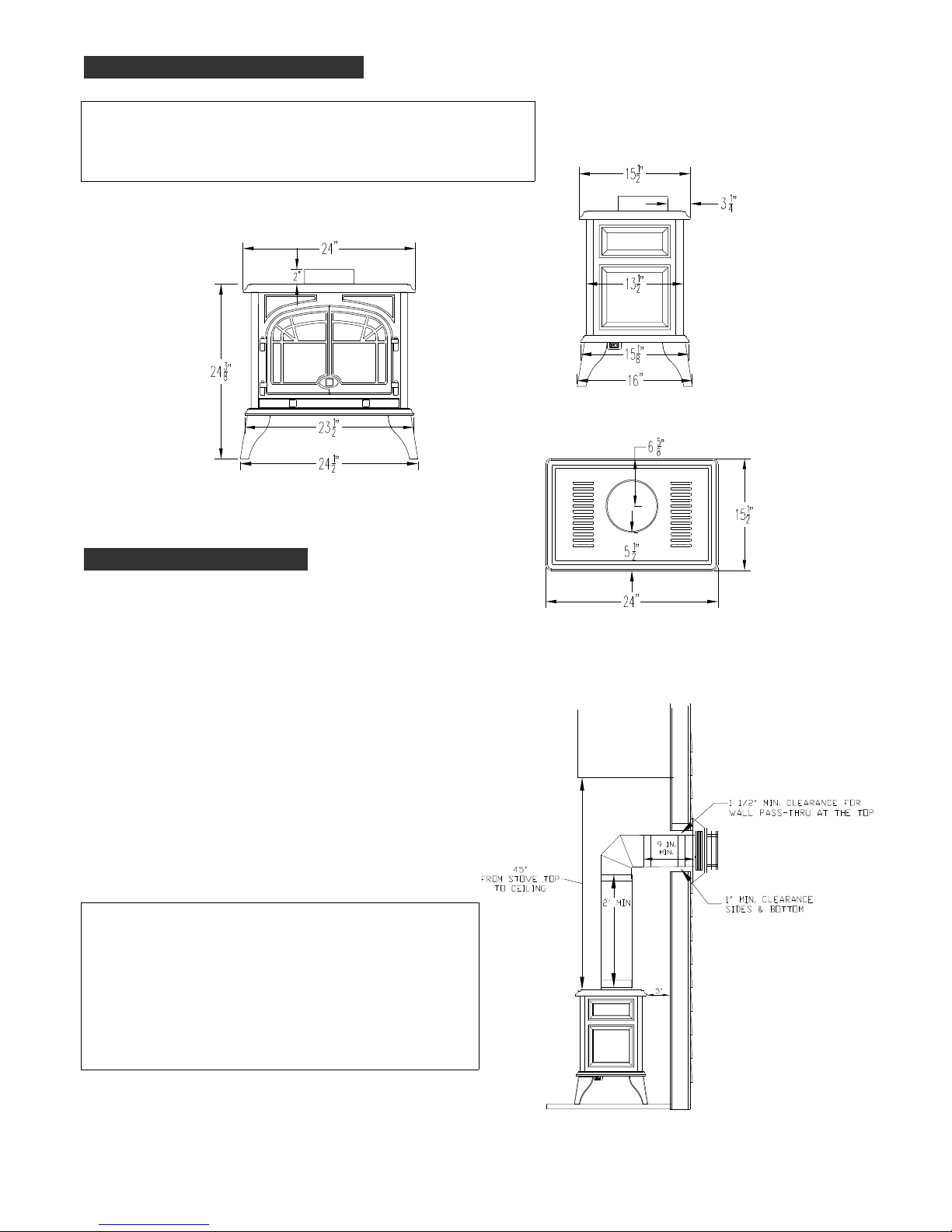
SPECIFICATIONS:
HEIGHT: 24 3/8" WIDTH (EXCLUDING LEGS): 24"
DEPTH : 16" WIDTH (INCLUDING LEGS): 24 1/2"
FLUE SIZE: 4" exhaust, 6 5/8" intake
Figure 1
CLEARANCES:
Refer to Figures 2A & 2B
The following clearances to combustibles must be
maintained:
Unit* to sidewall: 7"
Unit* to backwall: 5"
Unit top to ceiling: 45"
From vent pipe:
Horizontal runs:
Top: 1 ½" at wall pass-thru
Bottom & Sides: 1"
Vertical runs:
All sides: 1"
*Measurement is from the top corner of the fireplace.
PASS-THRU WALL THICKNESS:
The Dura-Vent DV-GS 4" x 6 5/8" wall thimble, is
designed for a minimum wall thickness of 4" and
maximum wall thickness of 7 ½”.
Figure 2A
The Ameri-Vent 4" x 6 5/8" wall thimble is designed for
a minimum wall thickness of 4 ½" and maximum wall
thickness of 8 ½".
Page 2
NOTE:
When the unit is installed directly on carpeting, tile, or other combustible materials other than wood flooring,
it must be installed on a metal or wood panel extending the full width and depth of the unit.
Figure 2B
VENTING GUIDELINES
THIS FIREPLACE IS APPROVED FOR USE WITH ONE OF THE FOLLOWING DIRECT VENT
CHIMNEY SYSTEMS FOR HORIZONTAL & VERTICAL TERMINATIONS:
T SIMPSON DURA-VENT DV-GS CHIMNEY SYSTEM 4" X 6 5/8"
T AMERI-VENT DIRECT VENT CHIMNEY SYSTEM 4" X 6 5/8"
IMPORTANT: This fireplace is manufactured with the appropriate adaptor for proper connection of
either of these systems.
Contact your dealer for the appropriate vent kit and components part numbers for the chimney system
required for your specific venting application.
Refer to the chimney manufacturer’s installation manual for complete installation instructions.
Installation must conform with the venting requirements & restrictions as outlined in this manual.
IMPORTANT: Consult the local and national installation codes to assure that adequate combustion and
ventilation air is available.
Page 3
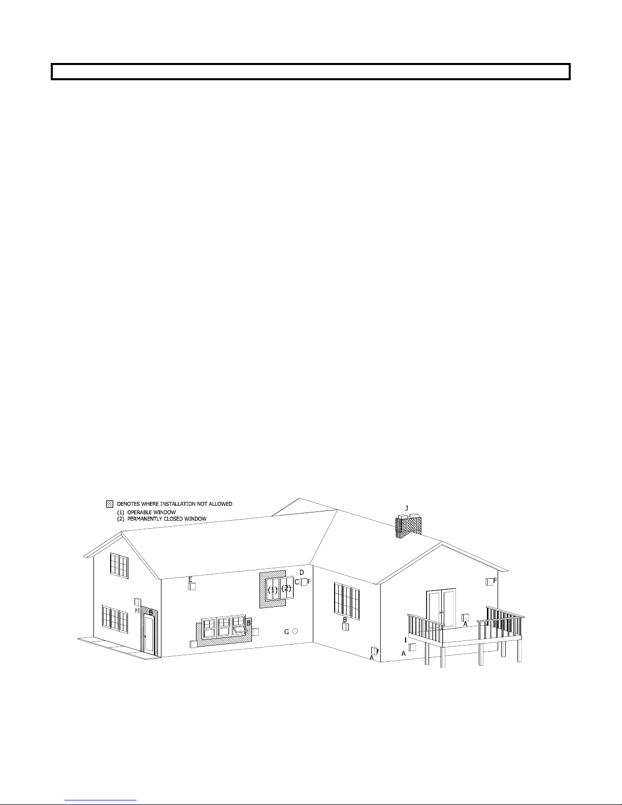
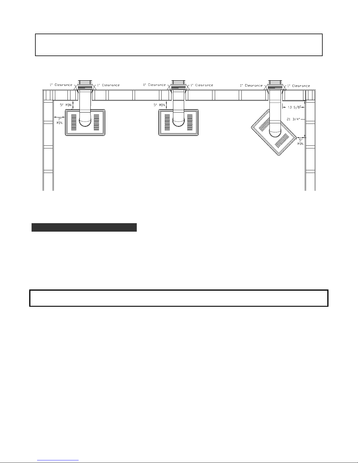
TERMINATION VENT CAP LOCATION:
This gas appliance must not be connected to a chimney flue serving another type of appliance.
GENERAL:
1. Terminations against vinyl siding must use a vinyl siding protector. Follow instructions included.
2. DO NOT RECESS TERMINATION KIT INTO OUTSIDE BUILDING MATERIALS - i.e.: brick, stone, siding, etc..
If necessary, extend framing so that termination kit will be exposed once building materials are installed.
3. Vent termination must not be located where it will become plugged by snow or other material. The flow
of combustion and ventilation air must be not obstructed.
S Above grade, veranda, porch, deck, balcony - 12". (A)
S Operable window - 12". (B)
S Permanently closed window* - 12" (recommended to prevent condensation on window). (C)
S Ventilated soffit* - 24". (D)
S Unventilated soffit* - 12". (E)
S Outside / inside corner* - 12". (F)
S Meter / Regulator: NOT TO BE INSTALLED ABOVE within 3 ft. horizontally from the center line of the regulator.
S Service regulator vent outlet - 3 ft. radius.
S Non-mechanical air supply inlet to building - 12".
S Combustion air inlet to any other appliance - 12".
S Mechanical air supply inlet. (G) - CANADA: 6 ft. US: 3 ft. above if within 10 ft. horizontally.
S Above furnace exhaust or inlet - 12".
S Above paved side-walk or paved driveway located on public property - 7 ft. (H)
NOTE: A vent cannot be located directly above a side-walk or paved driveway that is located between two single
family dwelling and serves both dwellings.
S Under veranda, porch, deck, or balcony (must be fully opened on a min. of 2 sides) - 12". (I)
S Between two horizontal terminations - 12".
S Between two vertical terminations - 12". (J) - Note: May be the same height.
NOTE: Massachusetts installations: 10 ft.
*Clearance must be in accordance with local installation codes & the requirements of the gas supplier.
Figure 3
*CHECK LOCAL & STATE BUILDING CODES FOR ADDITIONAL REQUIREMENTS AND/OR RESTRICTIONS.
Page 4
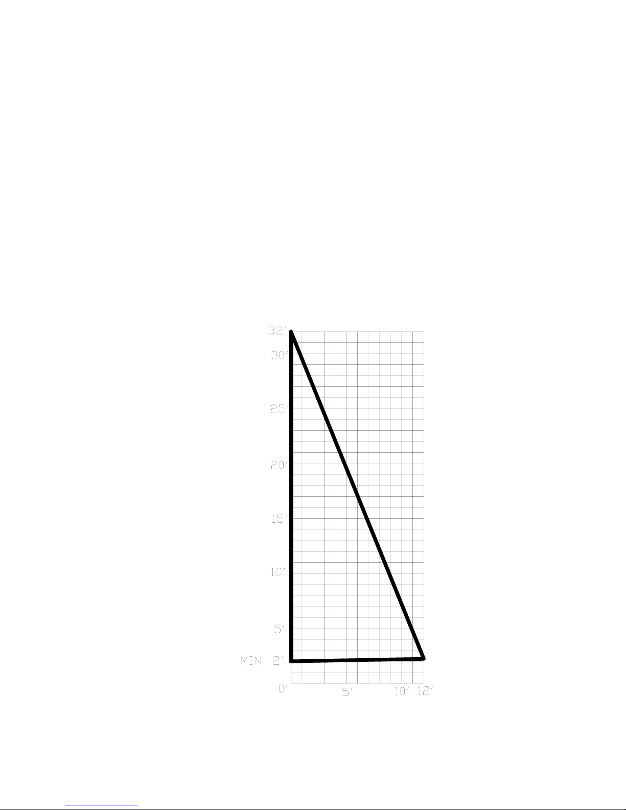
MINIMUM / MAXIMUM VENTING REQUIREMENTS:
Minimum vertical vent run:
Maximum vertical vent run:
RESTRICTOR REQUIREMENTS:
Minimum horizontal vent run:
Maximum horizontal vent run:
Elbows: (1) 90-degree elbow is included within the maximum vent runs. Each additional
elbow for horizontal terminations reduces the maximum horizontal run allowed by 3'.
Each additional elbow for vertical terminations reduces the maximum vertical rise
allowed by 3'.
2 ft.
32 ft.
Optional, depending on venting configuration.
9 in.
12 ft.*
*IMPORTANT: 1/4" incline per horizontal foot must be
maintained.
Page 5
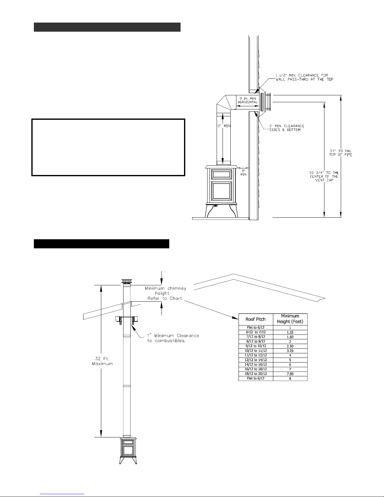
HORIZONTAL TERMINATIONS
EXAMPLE OF TYPICAL HORIZONTAL
TERMINATION
The minimum horizontal venting configuration is
2 ft. vertical from the top of the fireplace
followed by a 90-degree elbow, then 9 in. min.
horizontal thru exterior wall. See Figure 4.
IMPORTANT: PASS-THRU WALL THICKNESS:
The Dura-Vent DV-GS 4" x 6 5/8" wall thimble is
designed for a minimum wall thickness of 4" and
maximum wall thickness of 7 ½".
The Ameri-Vent 4" x 6 5/8" wall thimble is
designed for a minimum wall thickness of 4 ½"
and maximum wall thickness of 8 ½".
Figure 4
VERTICAL TERMINATIONS:
EXAMPLE OF TYPICAL VERTICAL TERMINATION
Figure 5
Page 6
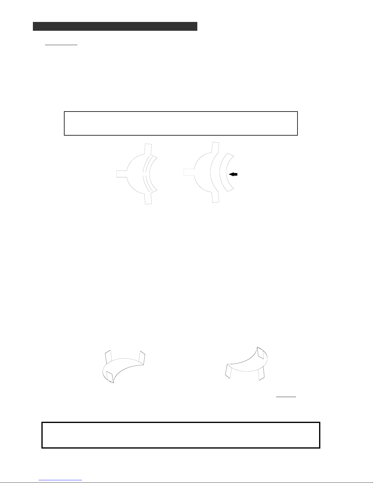
RESTRICTOR USAGE / INSTALLATION
The OPTIONAL restr ictor plate included in the fireplace components p acket can be installed as either
a large or small restrictor, depending on your specific venting configuration. It is sized as the
‘large’ restrictor. To reduce the restrictor to a smaller size, remove one or both sections (without
the tabs) at perforation and discard, Figure 6A.
There are several factors which can affect proper draft of the vent system and burner operation of
the fireplace. Installing a restrictor may be necessary to resolve the problem, even though it may
not be required under ‘normal conditions’.
IMPORTANT: DO NOT INSTALL A RESTRICTOR IF THE VENTING
CONFIGURATION IS AT THE MINIMUM VENTING
REQUIREMENTS!
Figure 6
A
Large Restrictor
Remove one or
Restrictor with
section removed
both sections
INSTALLING THE RESTRICTOR:
The restrictor may be placed inside the 4" exhaust pipe on the fireplace either from the top the
fireplace before connection of the chimney to the fireplace is made or from inside the firebox.
Access to the 4" exhaust collar from inside the firebox can be gained by removing the nuts securing
the exhaust baffle at the back.
ALTERNATE METHOD: The restrictor may be placed inside the 4" exhaust pipe on the last section
of chimney before the termination cap is installed.
To install the restrictor, refer to Figure 6B and bend the tabs ‘up’ far enough (approximately
80
o
) so
that when positioned into the exhaust pipe, will create tension to hold itself in place. Do not over
bend tabs! Slide the restrictor into the exhaust pipe with the tabs pointing toward you.
Figure 6B
Bend tabs approximately 80o up. Install with the tabs pointing toward you.
IMPORTANT: RE-INSTALL THE EXHAUST BAFFLE AFTER RESTRICTOR HAS BEEN
INSTALLED IF YOU USED THE ‘ALTERNATE METHOD’ INSTALLATION!
DO NOT OVER-TIGHTEN THE NUTS!
Page 7
 Loading...