

kozy heat Princeton PRC-36, Princeton PRC-36-RF, Princeton PRC-36-IPI, 55345, 55345-RF Installation And Operation Manual
...
Quality Fireplaces for Life
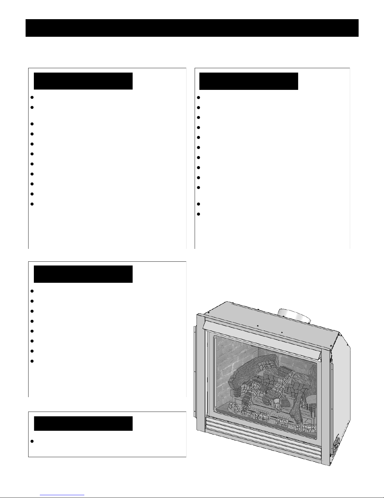
DIRECT VENT FIREPLACE
WARNING: This product must be installed by
a licensed plumber or gas fitter when installed
in the Commonwealth of Massachusetts.
IMPORTANT: Installation of a CO detector is
required in the fireplace room when installed in
the Commonwealth of Massachusetts.
INSTALLATION
AND
OPERATION MANUAL
INSTALLER: LEAVE THIS MANUAL WITH THE APPLIANCE.
CONSUMER: RETAIN THIS MANUAL FOR FUTURE REFERENCE.
DO NOT
DISCARD
WARNING: If the information in these instructions are not followed exactly, a fire or
explosion may result, causing property damage, personal injury or loss of life.
◙ Do not store or use gasoline or other flammable vapors and liquids in the vicinity of this or
any other appliance.
IF YOU SMELL GAS:
◙ Do not light any appliance.
◙ Do not touch any electrical switch: do not use any phone in your building.
◙ Immediately call gas supplier from a neighbors phone. Follow the gas supplier instructions.
◙ If you cannot reach your gas supplier, call the fire department.
◙ Installation and service must be performed by a qualified installer, service agency or the gas
supplier.
This appliance may be installed in an aftermarket permanently located, manufactured (mobile) home,
where not prohibited by local codes.
This appliance is only for use with the type (s) of gas indicated on
the rating plate. A conversion kit is supplied with the appliance.
www.kozyheat.com
October 2009
PRC-R08
INTRODUCTION
Read this manual before installing or operating this appliance.
Please retain this owner’s manual for future reference.
CONGRATULATIONS!
We welcome you as a new owner of a Kozy Heat gas fireplace. Kozy Heat
products are designed with superior components and materials and assembled by
trained craftsmen who take pride in their work. The burner and valve assembly are
100% test-fired and the complete fireplace is thoroughly inspected before packaging
to ensure that you receive a quality product. Our commitment to quality and
customer satisfaction have remained the same for over 30 years. We offer a
complete line of gas and wood fireplaces, unique cabinets and stylish accessories to
compliment any décor. Adding a fireplace is one of the best ways to increase the
value of your home and we are proud to offer a network of dealers throughout the
country to help make your experience everything you imagine. We pride ourselves in
being dedicated to not only function and reliability, but customer safety as well.
We offer our continual support and guidance to help you achieve the maximum
benefit and enjoyment from your Kozy Heat gas fireplace.
Jim Hussong Dudley Hussong
President Board Chairman
Homeowner Reference Information
We recommend that you record the following information about your fireplace.
Model Name:______________________________ Date purchased/installed:____________
Serial Number:____________________________ Location on fireplace:_______________
Dealership purchased from:__________________ Dealer Phone:_____________________
Notes:_____________________________________________________________________
__________________________________________________________________________
__________________________________________________________________________
PAGE 1
TABLE OF CONTENTS
INTRODUCTION
Introduction and Homeowner Reference Information 1
TABLE OF CONTENTS
Table of Contents 2
SAFETY INFORMATION
Safety Information 3
FEATURES
Features 4
COMMONWEALTH OF MASSACHUSETTS INFORMATION
Commonwealth of Massachusetts Information 5
SPECIFICATIONS
Fireplace Dimensions 6-7
Clearances 7
Components List 8
Installation Overview 9
Placement Clearance Requirements 9
PREPARE THE FIREPLACE
Stand-Off Assembly & Installation 10
Horizontal Vent Heat Shield Installation 11
Nailing Flange Assembly & Installation 11
FRAMING
Wall Enclosure Rough Opening 12
Minimum Finished Opening Dimensions 12
Horizontal Terminations 13
Vertical Terminations 13
TYPICAL INSTALLATION OPTIONS
Typical Installation Options 14
MANTEL REQUIREMENTS
Mantel Requirements 15
GLASS FRAME ASSEMBLY
Glass Frame Assembly Removal 16
Glass Frame Assembly Installation 16
FAN INSTALLATION
TMT-028 (PRC-36 only) Optional Fan Installation 17-18
GAS LINE CONNECTION
Gas Line Connection 19-20
PRC-36 THERMOSTAT / WALL SWITCH / REMOTE
PRC-36 Thermostat / Wall Switch / Remote 21
VENTING
Approved Venting 22
Horizontal Vent System Clearances 22
Horizontal Termination Minimum / Maximum 22
#800-WPT Wall Pass-Thru Installation Instructions 23
Horizontal Min. / Max. Venting Illustrations 24-25
Vertical Vent System Clearances 26
Combustion Air Intake Settings 26
Horizontal / Vertical Combination Venting 26
Vertical Min. / Max. Venting Illustrations 27
VENTING (cont.)
Restrictor Installation 27
Horizontal & Vertical Combination Venting Illustration 28
#800 Series Flex Vent Installation Instructions 29-30
Termination Vent Cap Location 31
Vent Termination Clearances 32
#MTK-BLK BACK LIGHT KIT (PRC-36-IPI STANDARD)
#MTK-BLK Back Light Kit (PRC-36-IPI Standard) 33
LOG SET INSTALLATION
Log Set Installation 34-36
MILLIVOLT BOARD
Millivolt Board Removal 37
Millivolt Board Installation 38
GRILL SET
Grill Set Installation 39
Grill Set Removal 39
PRC-36 OPERATING INSTRUCTIONS
PRC-36 Valve and Pilot Assembly Components 40
PRC-36 Lighting and Shutdown Instructions 41-43
PRC-36 Pressure Testing 44
PRC-36-RF OPERATING INSTRUCTIONS
PRC-36-RF Valve and Pilot Assembly Components 45
PRC-36-RF Lighting and Shutdown Instructions 46-48
PRC-36-RF Pressure Testing 49
PRC-36-RF Remote Receiver Functions 50-51
PRC-36-IPI OPERATING INSTRUCTIONS
PRC-36-IPI Wiring Schematics 52
PRC-36-IPI Valve and Pilot Assembly Components 53
PRC-36-IPI Control Module Components 54
PRC-36-IPI Remote Control Components 55
PRC-36-IPI Information and Remote Control Operation 56-59
PRC-36-IPI Lighting and Shutdown 60-61
PRC-36-IPI Pressure Testing 62
PRC-36-IPI Error Codes 63
FINALIZING THE INSTALLATION
Burner Tube Adjustment / Troubleshooting 64
Restrictor Troubleshooting / Installation after Termination Completion 65
Heat Damper Operation 66
MAINTENANCE
Maintenance 67
TROUBLESHOOTING
PRC-36 Troubleshooting 68-70
PRC-36-RF Troubleshooting 71-73
PRC-36-IPI Troubleshooting 74-75
REPLACEMENT PARTS LIST
Replacement Parts List 76-77
WARRANTY
Warranty 78-79
PAGE 2
SAFETY INFORMATION
This fireplace has been tested to and complies with ANSI Z21.88a-2007·CSA 2.33a-2007·CSA P.4.1-02 “VENTED GAS FIREPLACE
HEATERS” by OMNI-Test Laboratories, Portland, OR. Installation must conform with local building codes or in the absence of local
building codes, with the National Fuel Gas Code, ANSIZ223.1/NFPA 54 - Current Edition, or the Natural or Propane Installation Code,
CSAB149.1
Installation and repair should be done only by a qualified service person. The appliance should be
inspected by a qualified service person before use. Annual inspection by a qualified service person is
required to maintain warranty. More frequent cleaning may be required due to excessive lint from
carpeting, bedding materials, etc. It is imperative that control compartments, burners and
circulation air passageways of the appliance be kept clean.
If this appliance is installed directly on carpeting, tile or other combustible material other than wood
flooring, the appliance shall be installed on a metal or wood panel extending the full width and depth
of the appliance.
Children and adults should be alerted to the hazards of high surface temperatures and should stay
away to avoid burns or clothing ignition.
Young children should be carefully supervised when they are in the same room as the appliance.
Clothing or other flammable material should not be place on or near the appliance.
Adequate accessibility clearances for servicing and proper operation must be maintained.
This appliance must not share or be connected to a chimney flue serving any other appliance.
Keep area around the appliance clear of combustible materials, gasoline and other flammable vapor
and liquids.
The flow of combustion and ventilation air must not be obstructed.
Due to high temperatures the appliance should be located out of traffic and away from furniture and
draperies.
The glass front or any part removed for servicing the appliance must be replaced prior to operating
the appliance. Work should be done by a qualified service technician.
Clean glass only when cool and only with non-abrasive cleansers.
Do not operate this appliance with the glass/frame assembly removed, cracked or broken. The glass
assembly, Part #PRC-057T, shall only be replaced as a complete unit, as supplied by Hussong Mfg.
Co., Inc. Replacement of the glass assembly must only be performed by a licensed or qualified service
person. DO NOT SUBSTITUTE MATERIALS.
Do not strike or slam glass assembly.
Any safety screen or guard removed for servicing the appliance must be replaced prior to operating
the appliance.
Under no circumstances should any solid fuel (wood, coal, paper or cardboard etc.) be used in this
appliance.
Keep burner and control compartment clean.
Do not use this fireplace if any part has been under water. Immediately call a qualified service
technician to inspect this appliance and to replace any part of the control system and any gas control
which has been under water.
PAGE 3
FEATURES
STANDARD FEATURES
High efficiency
High quality lifetime glass
23-3/4” x 30-1/4” (603 mm x 768 mm)
Quick latch glass frame assembly
Upper grill / hood & lower grill (black)
Accepts rigid pipe or Kozy Heat flexible vent system
High - Low regulator
Patented log design
Automatic fan kit (2) - 75 CFM*
Light Kit**
Refractory brick lining
Minnesota Energy Code compliant to 50 pascals
*Standard on RF and IPI models
**Standard on IPI models
***Standard on Regular and RF models
SAFETY FEATURES
Each unit factory tested!
Tested by OMNI - Test Laboratories
Sealed combustion chamber
Standing pilot ignition***
Intermittent or Standing pilot ignition*
Removable millivolt board
30-second delay pilot***
Flame sensing system (safety shutoff)**
Automatic pressure relief glass system
Requires no electricity to operate
(excluding fan & light kit)
Bedroom and mobile home approved
Canadian approved
*Standard on RF and IPI models
**Standard on IPI models
***Standard on Regular and RF models
OPTIONAL FEATURES
Red brick refractory
Light Kit**
Automatic fan kit* with variable speed control ( (2) 75 CFM)
Remote control* or thermostat remote control
Wall mount thermostat / wireless wall mount thermostat
Decorative full door faces in various styles and finishes
Mission design doors in various finishes
Various cabinet & flush surrounds
*Standard on RF and IPI models
**Standard on IPI models
***Standard on Regular and RF models
WEIGHT
Fireplace Weight (as packaged for shipment)
183 lbs. (83.01 kg)
PAGE 4

COMMONWEALTH OF MASSACHUSETTS REQUIREMENTS
NOTE: The following requirements reference
various Massachusetts and national codes not
contained in this manual.
For all sidewall horizontally vented gas fueled equipment installed in every dwelling, building or structure used in whole or in part for residential purposes,
including those owned or operated by the Commonwealth and where the side wall exhaust vent termination is less than (7) feet above finished grade in the
area of the venting, including but not limited to decks and porches, the following requirements shall be satisfied:
INSTALLATION OF CARBON MONOXIDE DETECTORS
At the time of installation of the side wall horizontally vented gas fueled equipment, the installing plumber or gas -fitter shall observe that a hard wired
carbon monoxide detector with an alarm and battery back-up is installed on the floor level where the gas equipment is to be installed. In addition, the installing plumber or gas-fitter shall observe that a battery operated or hard wired carbon monoxide detector is installed on each additional level of the dwelling, building or structure served by the side wall horizontal vented gas fueled equipment. It shall be the responsibility of the property owner to secure the
services of qualified licensed professionals for the installation of hard wired carbon monoxide detectors.
In the event that the side wall horizontally vented gas fueled equipment is installed in a crawl space or attic, the hard wired carbon monoxide detector with
alarm and battery back-up may be installed on the next adjacent floor level.
In the event that the requirements of this subdivision can not be met at the time of completion of installation, the owner shall have a period of thirty (30)
days to comply with the above requirements; provided, however, that during said thirty (30) day period, a battery operated carbon monoxide
APPROVED CARBON MONOXIDE DETECTORS
Each carbon monoxide detector as required in accordance with the above provisions shall comply with NFPA 720 and be ANSI/UL 2034 listed and IAS
certified.
SIGNAGE
A metal or plastic identification plate shall be permanently mounted to the exterior of the building at a minimum of eight (8) feet above grade directly in
line with the exhaust vent terminal for the horizontally vented gas fueled heating appliance or equipment. The sign shall read, in print no less the one-half
inch (1/2) in size, “GAS VENT DIRECTLY BELOW. KEEP CLEAR OF ALL OBSTRUCTIONS”.
INSPECTION
The state or local gas inspector of the side wall horizontally vented gas fueled equipment shall not approve the installation unless, upon inspection, the
inspector observes carbon monoxide detectors and signage installed in accordance with the provisions of 248 CMR 5.08 (2) (a) 1 through 4.
EXEMPTIONS
The following equipment is exempt from 248 CMR 5.08 (2) (a) 1 through 4:The equipment listed in Chapter 10 entitled “Equipment Not Required To Be
Vented” in the most current edition of NFPA 54 as adopted by the Board; and Product Approved side wall horizontally vented gas fueled equipment in-
stalled in a room or structure separate from the dwelling, building or structure used in whole or in part for residential purposes.
MANUFACTURER REQUIREMENTS - GAS EQUIPMENT VENTING SYSTEM PROVIDED
When the manufacturer of Product Approved side wall horizontally vented gas equipment provides a venting system design or ven ting system components with the equipment, the instructions provided by the manufacturer for installation of the equipment and the venting system shall include:
Detailed instructions for the installation of the venting system design or the venting system components; and
A complete parts list for the venting system design or venting system.
MANUFACTURER REQUIREMENTS - GAS EQUIPMENT VENTING SYSTEM NOT PROVIDED
When the manufacturer of Product Approved side wall horizontally vented gas equipment does not provide the parts for venting the flue gases, but identifies “special venting systems”, the following requirements shall be satisfied by the manufacturer:
The referenced “special venting systems” instructions shall be included with the appliance or equipment installation instructions and;
The “special venting systems” shall be Product Approved by the Board, and the instructions for that system shall include a parts list and detailed
installation instructions.
A copy of all installation instructions for all Product Approved side wall horizontally vented gas fueled equipment, all venting instructions, all parts lists
for venting instructions, and/or all venting design instructions shall remain with the appliance or equipment at the completion of the installation.
PAGE 5
18
1
8
"
460mm
7"
178mm
9
1
2
"
241mm
SPECIFICATIONS
18
1
8
"
460mm
21
3
8
"
543mm
24
5
8
"
625mm
7"
178mm
10
1
4
"
260mm
9
1
2
"
241mm
911mm
797mm
619mm
254mm
TOP
813mm
"10
"
8
3
24
32"
"
8
3
31
"
8
7
35
18
1
8
"
460mm
21
3
8
"
543mm
24
5
8
"
625mm
10
1
4
"
260mm
TOP
5
5
8
"
143mm
21
3
8
"
543mm
24
5
8
"
625mm
42"
1067mm
2
1
4
"
57mm
10
1
4
"
260mm
30
1
8
"
765mm
797mm
619mm
254mm
TOP
813mm
"10
"
8
3
24
32"
"
8
3
31
"
8
7
35
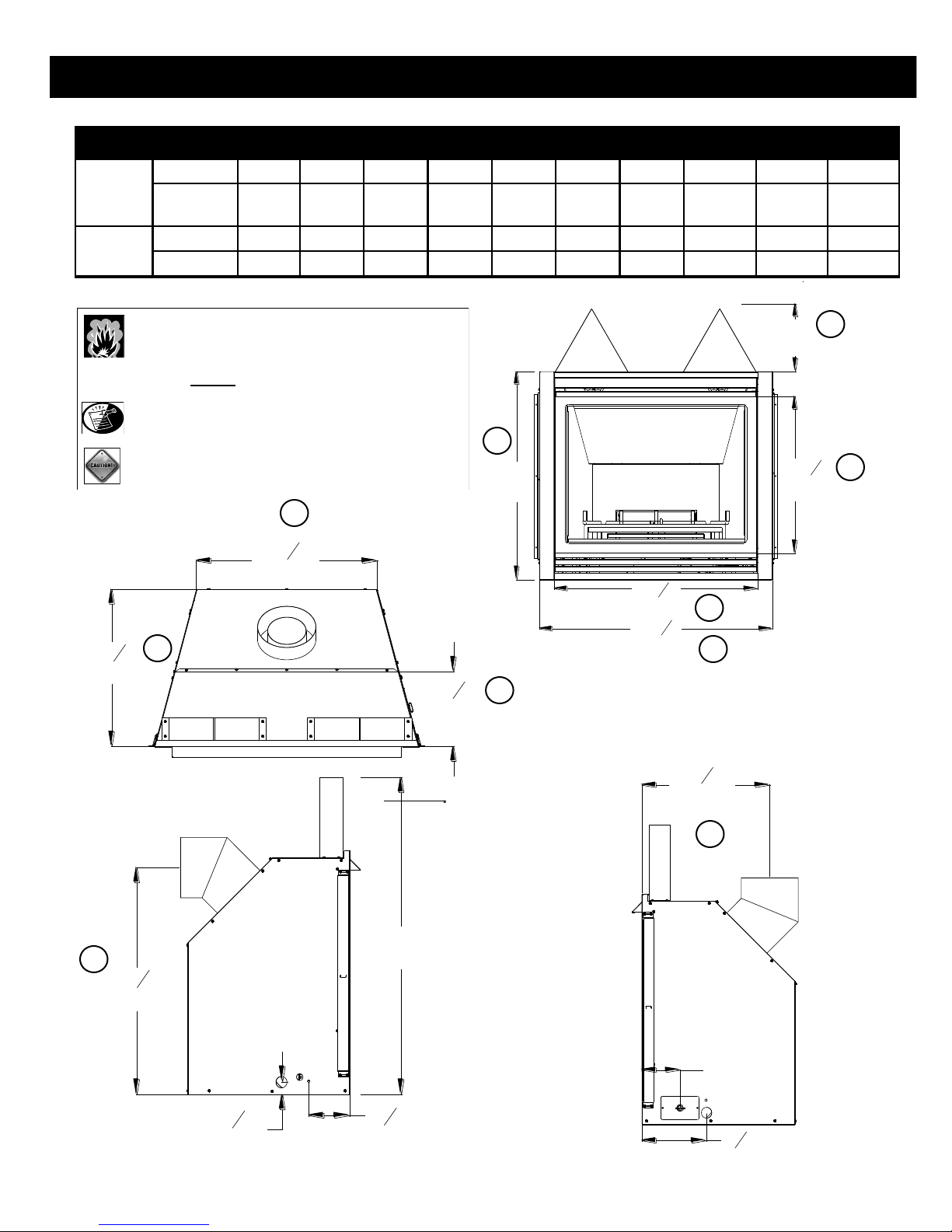
FIREPLACE DIMENSIONS
FIREPLACE
DIMENSIONS
LETTER KEY A B C D E F G H I J
DESCRIPTION Height Width Back Width Depth Opening
INCHES 32 35-7/8 24-5/8 21-3/8 31-3/8 24-3/8 10 18-1/8” 30-1/8 10-1/4
MILLIMETERS 813 911 625 543 797 619 254 460 765 260
Width
Glass Frame
Height
Stand-off
Height
Front to Vent
Center
(Vert. Term.)
Floor to Vent
Center
(Hor. Term.)
Front to
Angled Back
WARNING: NON-COMBUSTIBLE ZONE: STAND-OFFS PROVIDE
10” (254 mm) MINIMUM CLEARANCE TO HEADER.
USE ONLY NON-COMBUSTIBLE MATERIAL IN
DO NOT USE WOOD, SHEETROCK ETC. IN THIS
THIS AREA FOR ENTIRE WIDTH OF FIREPLACE.
ZONE.
NOTE: OTHER CLEARANCES APPLY. ALL CLEARANCES MUST
BE MAINTAINED. REFER TO PAGE 14 FOR MORE
INFORMATION.
CAUTION: STAND-OFF BRACKETS ARE NOT LOAD BEARING.
C
D
A
J
G
F
E
B
H
I
PAGE 6
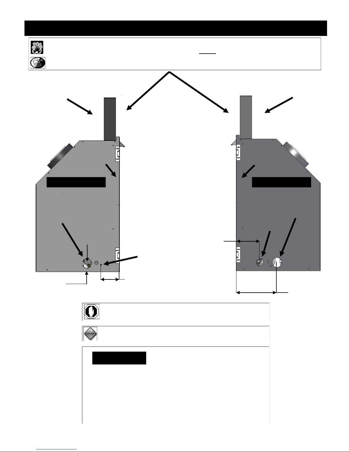
SPECIFICATIONS
WARNING: NON-COMBUSTIBLE ZONE: STAND-OFFS PROVIDE THE 10” (254 mm) MINIMUM CLEARANCE TO HEADER. USE ONLY NON -
COMBUSTIBLE MATERIAL IN THIS AREA FOR ENTIRE WIDTH OF FIREPLACE. DO NOT USE WOOD, SHEETROCK ETC. IN THIS ZONE.
NOTE: OTHER CLEARANCES APPLY. ALL CLEARANCES MUST BE MAINTAINED. REFER TO PAGE 14 FOR MORE INFORMATION.
STAND-OFF
FIREPLACE FRONT FIREPLACE FRONT
GAS LINE HOLE
STAND-OFF
RIGHT SIDE LEFT SIDE
GAS LINE HOLE
ELECTRICAL
ACCESS
7”
(178 mm)
THERMOSTAT WIRE
2-1/4”
(57 mm)
5-5/8”
(143 mm)
9-1/2”
(241 mm)
WARNING: TOP STAND-OFF BRACKET MUST BE ATTACHED TO
FIREPLACE. DO NOT REMOVE.
CAUTION: STAND-OFF BRACKETS ARE NOT LOAD BEARING.
CLEARANCES
■ From fireplace face top to framing………………………….…..10" (254 mm)
■ From fireplace left & right sides & back…………………………..½" (13 mm)
■ Surround sides (flush)…………………………………………….…¼" (6 mm)
■ Fireplace bottom to flooring…………………………………..………………0
■ Fireplace top to ceiling………………………………………….31" (787 mm)
■ Fireplace side to adjacent sidewall……………………………...10" (254 mm)
■ Fireplace front…………………………………………………...36” (914 mm)
■ Mantel 10" (254 mm) deep from top of fireplace…………….…15" (381 mm)
PAGE 7

SPECIFICATIONS
MODEL #PRC-36 COMPONENTS
(#PRC-770) - Millivolt Board Assembly with 18” Flexible Gas
Line attached
(#700-203) - Manual Gas Shut-off Valve
(#PRC-135) - Burner / Log Grate Assembly
(#PRC-G900) - Refractory Set
(#PRC-500) - Log Package
(#PRC-057T) - Glass Frame Assembly
(#OCK-S5271) - LP Conversion Kit
(#600-083) - Receptacle/Speed Control Assy. with (3) Wire Nuts
(#942-085) - 5” Restrictor Plate
(#500-PRC) - Grill Assembly: Upper Hood, Upper Louver,
Lower Grill
MODEL #PRC-36-IPI COMPONENTS
MODEL #PRC-36-RF COMPONENTS
(#PRC-800-RF) - Millivolt Board Assembly with 18” Flexible
Gas Line attached
(#700-203) - Manual Gas Shut-off Valve
(#PRC-135) - Burner / Log Grate Assembly
(#PRC-G900) - Refractory Set
(#PRC-500) - Log Package
(#RF-028) - RF Fan Kit
(#PRC-057T) - Glass Frame Assembly
(#OCK-H5271L-RF) - LP Conversion Kit
(#700-108) - Remote control
(#942-085) - 5” Restrictor Plate
(#500-PRC) - Grill Assembly: Upper Hood, Upper Louver,
Lower Grill
(#PRC-600-IPI) - IPI Board Assembly with 18” Flexible Gas
Line attached
(#700-203) - Manual Gas Shut-off Valve
(#PRC-135) - Burner / Log Grate Assembly
(#PRC-G900) - Refractory Set
(#PRC-500) - Log Package
(#IPI-028) - IPI Fan Kit
(#MTK-BLK) - Back Light Kit
(#PRC-057T) - Glass Frame Assembly
(#OCK-A5271L-IPI) - LP Conversion Kit
(#700-208) - Remote Control
(#600-002) - Double Receptacle Assembly with (3) Wire Nuts
(#942-085) - 5” Restrictor Plate
(#500-PRC) - Grill Assembly: Upper Hood, Upper Louver,
Lower Grill
PAGE 8

SPECIFICATIONS
INSTALLATION OVERVIEW
NOTE: The qualified installer should follow the procedure best suited for the installation.
1. Frame an opening for fireplace, allowing for vent installation and type of installation (corner, flat wall application).
2. If masonry (optional) will be used, prepare foundation for the masonry load. A lintel is required to support the added weight above the
fireplace.
3. Attach nailing flanges to fireplace.
4. Insert fireplace into framing.
5. Install hearth (if applicable).
6. Complete gas line installation.
7. Complete electrical hook-up. Install any standard or optional electrical components at this time.
8. Complete venting installation.
9. Secure fireplace to flooring through holes located in the outer box bottom and to framing with nailing flanges. Verify all clearances at
this point.
10. Install facing material, mantel or cabinetry, allowing room for optional full face doors, if applicable.
11. Install logs.
12. Install grills and optional decorative doors / faces.
13. Verify proper operation of fireplace and all components.
PLACEMENT CLEARANCE REQUIREMENTS
This fireplace must be installed on a level surface capable of supporting the fireplace and venting.
Fireplace must be placed directly on wood or non-combustible surface (not linoleum or carpet) extending entire depth and width of
fireplace.
Due to high surface temperatures, fireplace should be located out of traffic and away from furniture and draperies.
This fireplace may be installed in a bedroom.
Please be aware of the large amount of heat this fireplace will produce when determining a location.
PAGE 9
PREPARE THE FIREPLACE
STAND-OFF ASSEMBLY & INSTALLATION
WARNING: STAND-OFFS PROVIDE 10” (254 mm) MINIMUM CLEARANCE TO HEADER. USE ONLY NON-COMBUSTIBLE M ATERIAL IN THIS AREA
FOR ENTIRE WIDTH OF FIREPLACE. DO NOT USE WOOD, SHEETROCK ETC. IN THIS ZONE.
IMPORTANT: TOP STAND-OFF BRACKETS MUST BE FORMED AND ATTACHED PRIOR TO POSITIONING FIREPLACE INTO FRAMED OPENING.
CAUTION: STAND-OFF BRACKETS ARE NOT LOAD BEARING.
NOTE: OTHER CLEARANCES APPLY. ALL CLEARANCES MUST BE MAINTAINED. REFER TO PAGE 14 FOR MORE INFORMATION.
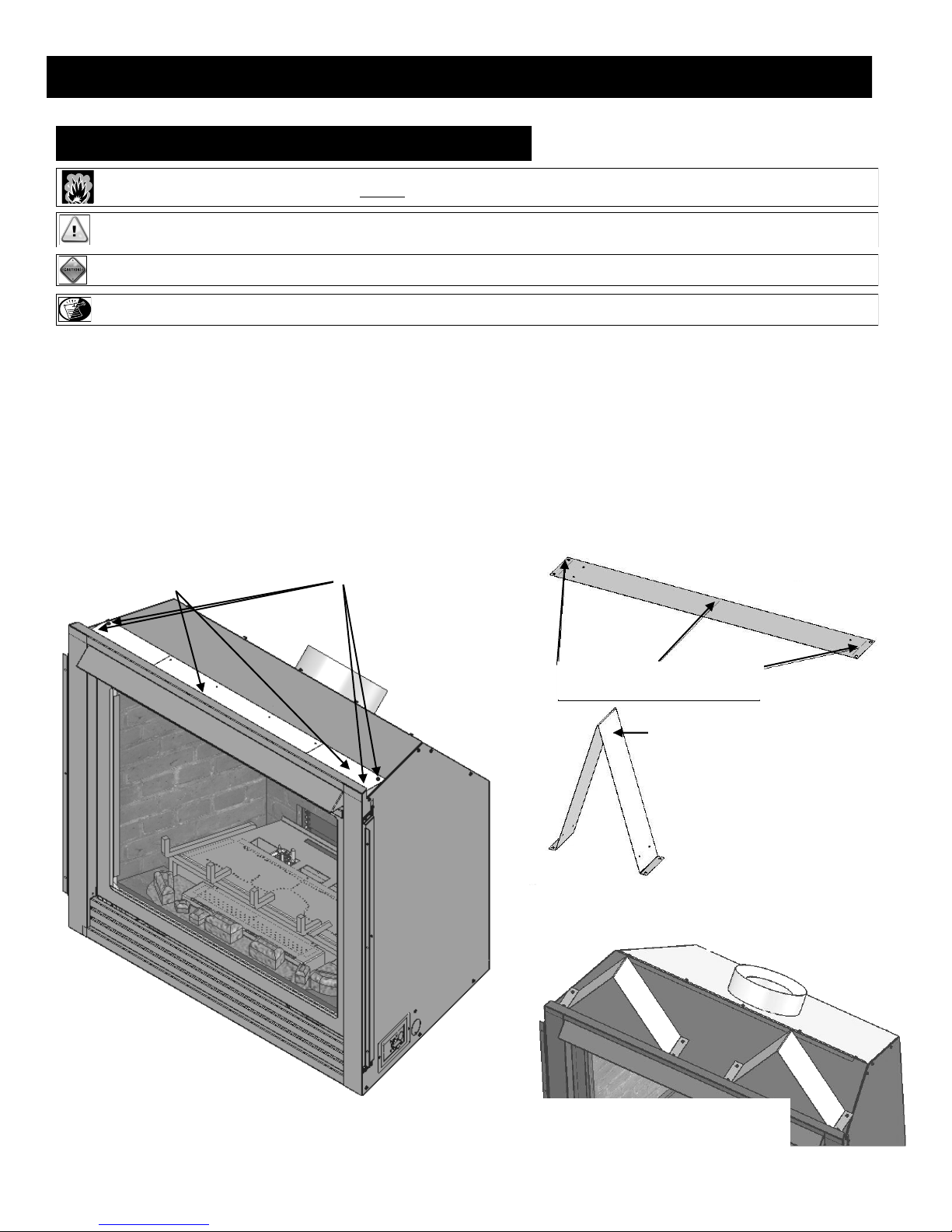
The top stand-off brackets are attached to fireplace top in a flat state for shipping.
1. Remove and save (4) screws securing stand-off heat shield and stand-off brackets, and (4) screws located under stand-off brackets.
2. Form each stand-off bracket as shown.
3. Re-attach stand-off brackets to fireplace using screws previously removed.
STAND-OFF BRACKETS
AS SHIPPED
REMOVE SCREWS SECURING
EACH STAND-OFF BRACKET
FORM STAND-OFF BY BENDING
AT PERFORATIONS AS SHOWN
FORMED STAND-OFF
STAND-OFF BRACKETS
INSTALLED
ATTACH BOTH STAND-OFF BRACKETS BY
ALIGNING WITH HOLES IN FIREPLACE TOP.
SECURE WITH (4) SCREWS AS SHOWN.
PAGE 10
PREPARE THE FIREPLACE
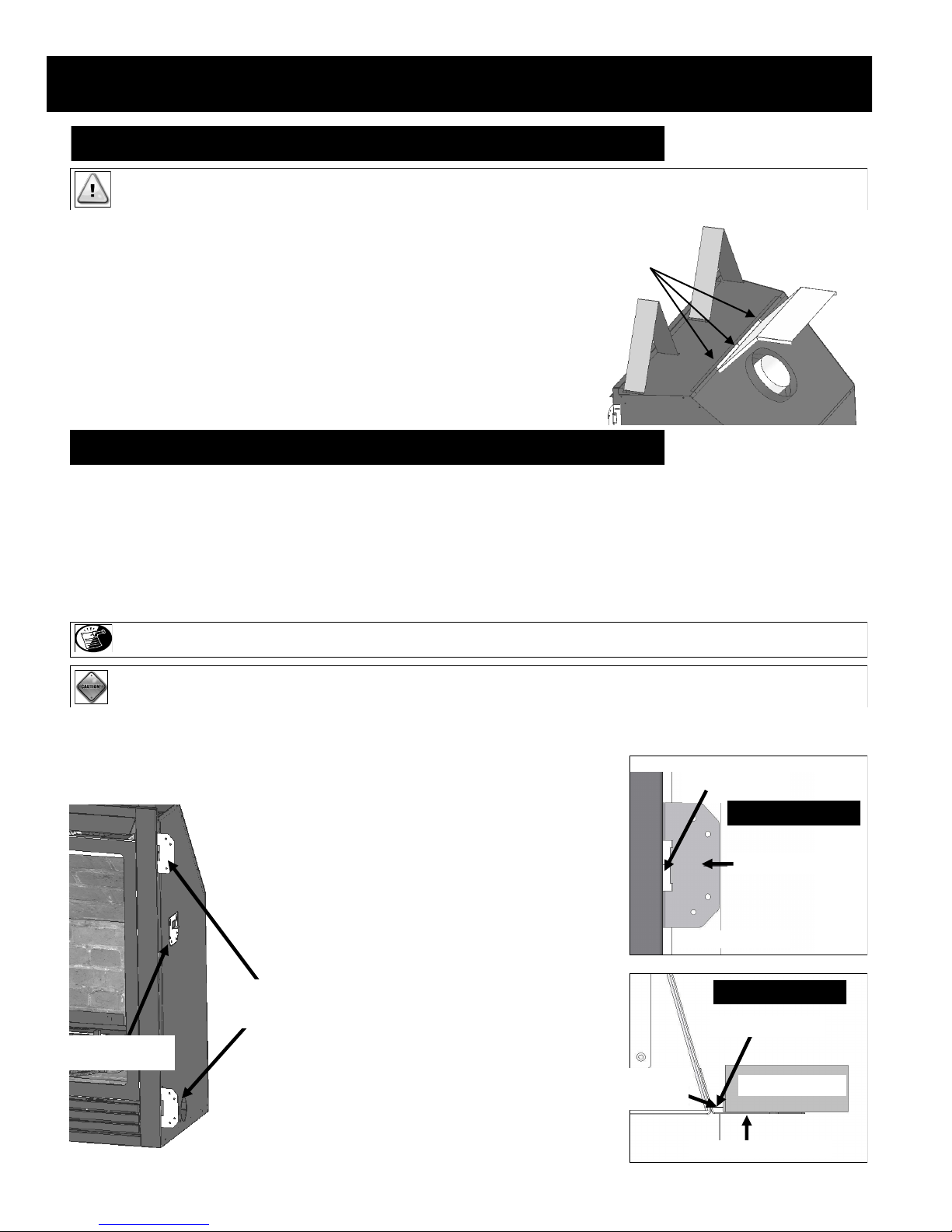
HORIZONTAL VENT HEAT SHIELD INSTALLATION
IMPORTANT: THE HORIZONTAL VENT HEAT SHIELD MUST BE INSTALLED WHEN USING A 45 -DEGREE ELBOW TO HORIZONTALLY
POSITION THE VENT SYSTEM. EXCEPTION: CORNER INSTALLATIONS
To Install Horizontal Vent Heat Shield:
1. Loosen, but do not remove center three screws at back of fireplace as
shown.
Attach here. Tighten screws.
2. Bend horizontal heat shield at perforation to a 45° angle. Slide (3) slots
on horizontal vent heat shield under loosened screws. Re-tighten screws.
NAILING FLANGE ASSEMBLY & INSTALLATION
1. Remove (4) nailing flanges from fireplace sides.
2. With the 1/4” (6 mm) stand-offs on nailing flanges facing away from fireplace, align nailing flange with holes on outside corners of
fireplace. Secure with screws (provided in components packet) through slots in nailing flanges.
3. Bend perforation on nailing flange until parallel with fireplace face. Do not bend toward fireplace face.
4. Position framing stud against 1/4” (6 mm) stand-off (located on backside of nailing flange). Secure with nails or screws.
NOTE: Depending on facing material, tabs can be adjusted forward or back up to 1/2” (13 mm).
CAUTION: NEVER PERMANENTLY REMOVE THESE ASSEMBLIES FROM FIREPLACE - THEY MUST BE SECURED IN PLACE REGARDLESS OF
FINISH MATERIAL USED.
When installed, nailing flanges provide the minimum 1/4” (6 mm) clearance from fireplace sides.
NAILING FLANGES
INSTALLED
AS SHIPPED
1/4” (6mm)
CLEARANCE
1/4” (6mm)
CLEARANCE
FRONT VIEW
NAILING FLANGE
FRAMING STUD
TOP VIEW
STAND-OFF
FRAMING STUD
NAILING FLANGE
PAGE 11
FRAMING
WALL ENCLOSURE ROUGH OPENING
IMPORTANT: Framing dimensions should allow for wall covering thickness and fireplace facing materials. If using a hearth, adjust
rough opening size as necessary to maintain at least minimum clearance requirements.
IMPORTANT: NON-COMBUSTIBLE FACING MATERIAL MAY BE APPLIED OVER (BUT NOT DIRECTLY TO) FIREPLACE FACE. THIS WILL
PREVENT FACING MATERIAL FROM FALLING OFF DUE TO HEAT EXPANSION. DO NOT OBSTRUCT THE FLOW OF
VENTILATION AIR.
MINIMUM FINISHED OPENING DIMENSIONS
HORIZONTAL VENTING
42”(1067 mm) High x 36-3/8”(924 mm) Wide x 21-7/8” (556 mm) Deep.
1/2” (13 mm) clearance at back and sides of fireplace must be maintained.
VERTICAL VENTING
42”(1067 mm) High x 36-3/8”(924 mm) Wide x 23-7/8” (607 mm) Deep.
2-1/2” (64 mm) clearance at back to maintain vent system clearance and 1/2” (13 mm) at sides of fireplace must be maintained.
NOTE: Provide adequate clearance in front of fireplace to operate lower grill, open and close optional decorative doors / full door faces,
access components, installation of gas line, fan, etc.
WARNING: DO NOT OBSTRUCT UPPER AND LOWER GRILL OPENINGS. ROOM AIR ENTERS THROUGH LOWER PASSAGE, IS HEATED AND
EXITS THROUGH UPPER PASSAGE. BLOCKING THESE PASSAGES MAY RESULT IN OVERHEATING, CREATING A POTENTIALLY
HAZARDOUS SITUATION.
Illustration at right requires a minimum 5” (127 mm)
exterior wall depth when using minimum horizontal venting.
*
Anything less than a 5” (127 mm) exterior wall depth requires
that you add that depth to the 21-7/8” (556 mm) dimension for
horizontal terminations to accommodate minimum venting.
5” (127 mm) exterior wall depth shown*
12-1/2” x (318 mm) H x 10-7/8” (277 mm) W opening
(required for horizontal terminations)
42”
(1067 mm)
PAGE 12
36-3/8”
(924 mm)
Hearth
Height
21-7/8”
(556 mm)

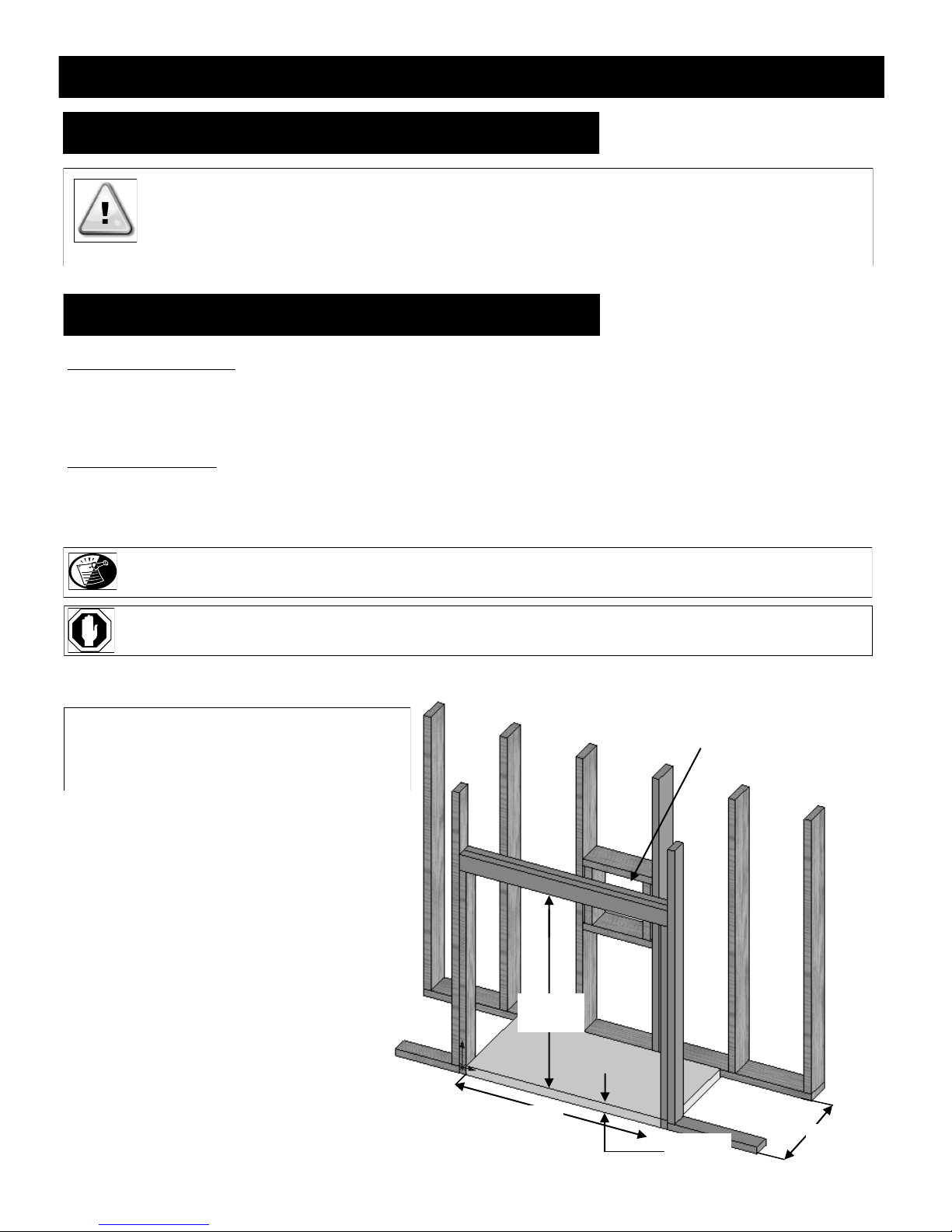
FRAMING
Determine exact position of your fireplace, including hearth height, width, and depth, (if applicable). If possible, place fireplace in such a
manner that vent termination will be placed between two studs, eliminating the need for additional framing.
If masonry is to be used (optional), prepare the necessary foundation for the masonry load. When masonry construction is being used, a lintel
must be used over the top of fireplace to support the added weight.
HEARTH EXTENSION REQUIREMENTS
NOTE: Consider height of hearth finish material (stone, brick, etc.) when building fireplace platform. The bottom of fireplace must be level
with finished hearth to allow for lower grill operation and proper fit of optional decorative full door faces.
WARNING: Install fireplace on hard metal or wood surface extending the full width and depth of fireplace.
Minimum platform size: 35-7/8” (911 mm) wide x 21-3/8” (543mm) deep.
FIRE HAZARD: Do NOT install directly on carpeting, vinyl, or any combustible material other than wood.
Non-combustible material (36” (914 mm) wide x 14” (357 mm) deep) required in
front of fireplace when fireplace is raised less than 2 inches.
If hearth is to be made of combustible material it must have a minimum height of
2” (51 mm) and a maximum depth of 6” ( 152 mm).
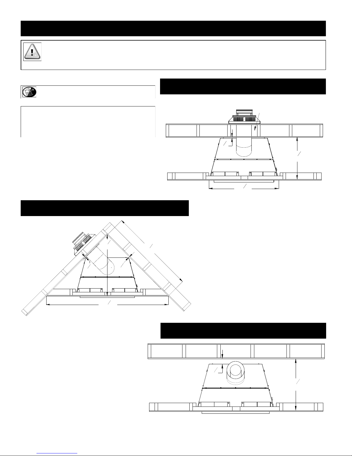
VERTICAL TERMINATIONS
Follow vent pipe manufacturer‟s installation instructions for vertical terminations.
A minimum 1” (25 mm) clearance on all sides of vertical vent pipe must be maintained.
NOTE: The included Horizontal Vent Heat Shield is not used for vertical
configurations.
IMPORTANT: Vent cap location must be in compliance with the guidelines on page
#31 of this manual.
HORIZONTAL TERMINATIONS
Follow vent pipe manufacturer‟s installation instructions for horizontal terminations.
Include required 1-1/2” (38 mm) top clearance and 1” (25 mm) sides and bottom clear-
ances for approved rigid vent systems and Kozy Heat #800 series flexible vent system.
MINIMUM HORIZONTAL FRAMING DIMENSIONS
RIGID PIPE OPTION #1 (see pages 22 & 24)
RIGID PIPE OPTION #2 (see pages 22 & 24)
RIGID PIPE CORNER INSTALLATION
VENT PIPE TOP (A) FRAMED OPENING TOP (B)
34-3/8” (873 mm) 37-3/8” (950 mm)
37-1/2” (953 mm) 40-1/2” (1029 mm)
45” (1143 mm) 48” (1219 mm)
FLEX PIPE
CAUTION: Cold air transfer area. The surrounding fireplace chase must comply with all clearances as outlined in this manual and be
constructed in compliance with local building codes. Outside walls should be insulated to prevent cold air from entering room.
CAUTION: Due to high temperatures, this fireplace should be located out of traffic areas and away from furniture and draperies.
37-3/8” (950 mm) 40-7/8” (1038 mm)
PAGE 13
71
1
4
"
1810mm
50
3
8
"
1280mm
35
5
8
"
905mm
1
2
"
13mm
1
2
"
13mm
3" clearance - sides
36
3
8
"
924mm
21
7
8
"
556mm
1
2
"
13mm
TYPICAL INSTALLATION OPTIONS
23
7
8
"
606mm
2
1
2
"
64mm
IMPORTANT: KOZY HEAT WALL THIMBLE PASS-THRU (#800-WPT or #800-WPT2) MUST BE USED ON ALL HORIZONTAL VENT RUNS.
FOLLOW INSTRUCTIONS ON PAGE 23 OF THIS INSTALLATION MANUAL.
IMPORTANT: THE HORIZONTAL HEAT SHIELD INCLUDED WITH THIS FIREPLACE MUST BE INSTALLED WHEN USING A 45-DEGREE
ELBOW DIRECTLY OFF TOP OF UNIT TO HORIZONTALLY POSITION VENT SYSTEM. EXCEPTION: CORNER INSTALLATIONS.
NOTE: HORIZONTAL VENT HEAT SHIELD NOT SHOWN
FOR CLARITY PURPOSES ONLY.
Illustration at right requires a minimum 5” (127 mm) exterior
wall depth when using minimum horizontal venting. Anything less
*
than a 5” (127 mm) exterior wall depth requires that you add that
depth to the 21-7/8” (556 mm) dimension to accommodate mini-
mum venting.
TYPICAL CORNER INSTALLATION
TYPICAL HORIZONTAL INSTALLATION
5” (127 mm) exterior wall depth shown*
*
TYPICAL VERTICAL INSTALLATION
PAGE 14
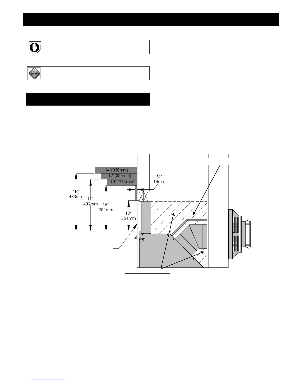
MANTEL REQUIREMENTS
WARNING: TOP STAND-OFF BRACKETS MUST BE ASSEMBLED
AND ATTACHED TO FIREPLACE. DO NOT REMOVE.
CAUTION: STAND-OFF BRACKETS ARE NOT LOAD BEARING.
NON-COMBUSTIBLE ZONE:
Rigid pipe: 1-1/2” (38 mm) above elbow for entire width and depth (behind header) of fireplace.
#800 series flexible venting: 1” (25 mm) above elbow for entire width and depth (behind header) of fireplace.
HORIZONTAL VENT HEAT SHIELD
NON-COMBUSTIBLE MATERIAL ONLY
NO MATERIALS ALLOWED ON TOP OF FIREPLACE WITHIN SHADED AREA FOR
ENTIRE WIDTH & DEPTH OF FIREPLACE. THIS AIR SPACE MUST REMAIN OPEN.
NON-COMBUSTIBLE ZONE:
PAGE 15

GLASS FRAME ASSEMBLY
REMOVE GLASS FRAME ASSEMBLY
CAUTION: TO PREVENT THE GLASS FRAME ASSEMBLY FROM FALLING FROM THE FIREPLACE AND BECOMING DAMAGED, FOLLOW
THESE INSTRUCTIONS EXACTLY WHEN REMOVING GLASS FRAME ASSEMBLY.
A. Locate spring-loaded handles securing glass frame assembly at top & bottom of firebox.
B. Pull bottom handles out and „down‟ to release glass frame assembly bottom.
C. Pull top handles out and „up‟ to release glass frame assembly top.
D. Remove glass frame assembly from fireplace.
INSTALL GLASS FRAME ASSEMBLY
CAUTION: TO PREVENT GLASS FRAME ASSEMBLY FROM FALLING OFF WHEN INSTALLING, SECURE TOP GLASS LATCH BRACKETS BEFORE
SECURING BOTTOM BRACKETS.
A. Place glass frame assembly onto fireplace front.
B. Pull top handles out and „down‟ to secure glass frame assembly top.
C. Pull bottom handles out and „up‟ to secure glass frame assembly bottom.
Pull latches „out‟ and „up‟ to release glass frame
assembly top.
Pull latches „out‟ and „down‟ to attach glass frame
assembly top.
Pull latches „out‟ and „down‟ to release glass frame
assembly bottom.
Pull latches „out‟ and „up‟ to attach glass frame
assembly bottom.
WARNING: DO NOT OPERATE THIS FIREPLACE WITH THE GLASS REMOVED, CRACKED OR BROKEN.
REPLACEMENT OF GLASS FRAME ASSEMBLY, #PRC -057T SHOULD BE DONE BY A LICENSED OR QUALIFIED SERVICE PERSON.
WARNING: DO NOT REMOVE GLASS ASSEM BLY WHEN HOT!
PAGE 16
OPTIONAL FAN INSTALLATION (PRC-36 only)
INSTALLATION OF THIS FAN SHOULD BE DONE ONLY BY A QUALIFIED INSTALLER
WARNING: MAKE SURE HOUSEHOLD BREAKER IS SHUT OFF PRIOR TO WORKING ON ANY ELECTRICAL LINES.
IMPORTANT: If installing a fan, it is easier to complete before the millivolt board is connected to the gas line. Wiring must be done
before enclosing fireplace sides. An electrical box and romex connector are pre-installed on a removable panel on the
right side of fireplace. A receptacle / speed control assembly and (3) wire nuts are included in fireplace components
packet.
The optional fan kit #TRF-028 includes:
(2) 75 CFM fan with temperature control switch and 4 ft. (1219 mm) fan cord
(4) 1/4” nuts
NOTE: Code approved line voltage wiring 14 gauge or better must be used when wiring this assembly. Refer local electrical codes for
specific requirements.
WARNING: THIS APPLIANCE IS EQUIPPED WITH A THREE-PRONG (GROUNDING) PLUG FOR PROTECTION AGAINST SHOCK HAZARD
AND SHOULD BE PLUGGED DIRECTLY INTO A PROPERLY GROUNDED THREE-PRONG RECEPTACLE. DO NOT CUT OR
REMOVE GROUNDING PRONG FROM THIS PLUG.
Temperature Switch:
Incoming wiring
110V - 120V
Magnetically attaches to bottom of
Electrical Box
110V - 120V
60Hz
Speed Control / Receptacle Assembly
firebox.
The following components must be removed from the fireplace prior to installation of this fan. Refer to corresponding pages in this
installation manual for assistance if necessary.
A. Upper hood, upper louver & lower grill, if installed. Page 39.
B. Glass assembly. Page 16.
PAGE 17
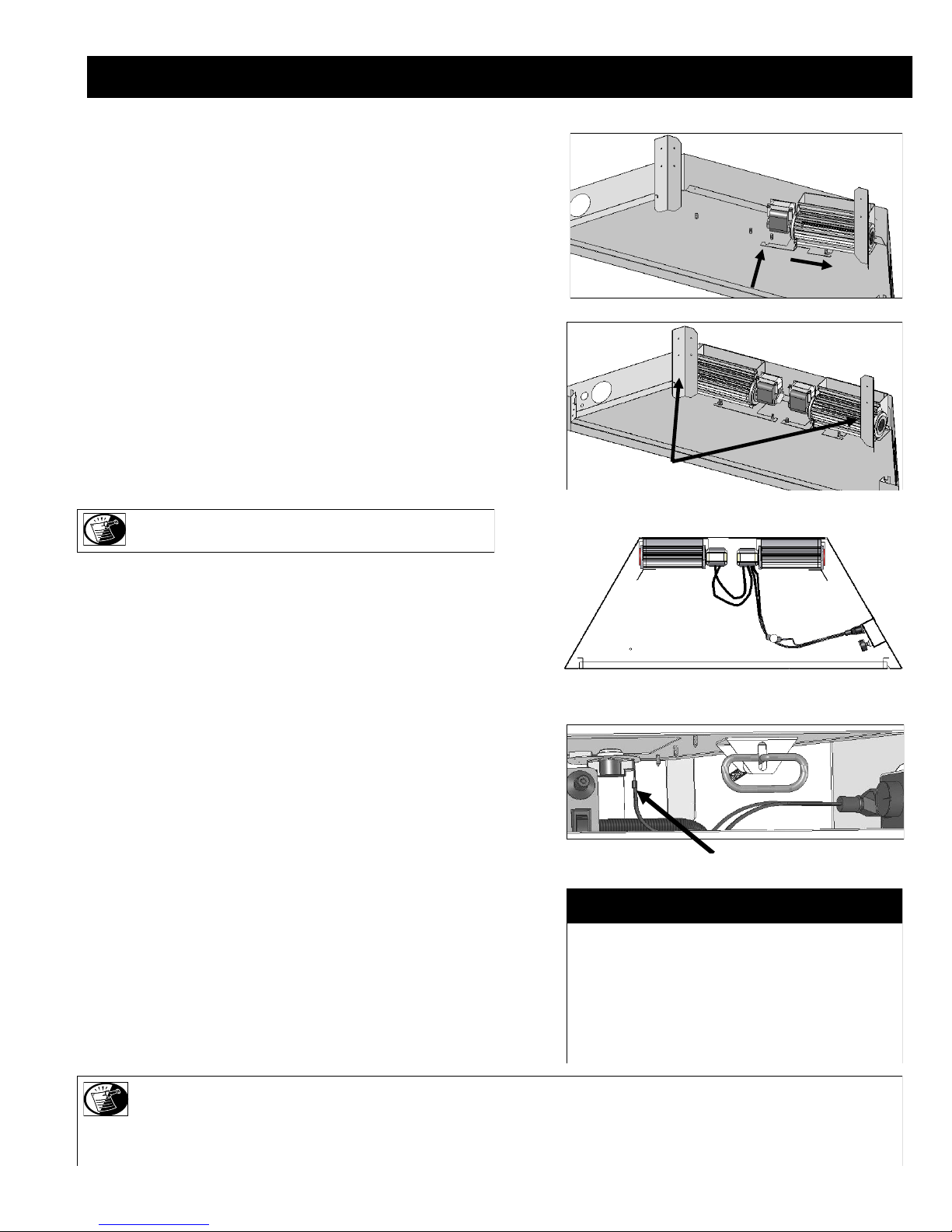
OPTIONAL FAN INSTALLATION (PRC-36 only)
1. Insert fans through lower grill opening, push to the back, positioning
behind legs. Align mounting slots in fan brackets onto mounting studs.
Secure with nuts.
2. Connect fan wiring by attaching connectors on right fan onto terminals
on left fan.
3. From inside lower right grill opening, loosen screw securing removable
access panel (with electrical box & romex connector installed). Remove
panel.
4. Insert 110V - 120V wiring (with ground) through romex connector and
wire to the speed control / receptacle assembly, matching black (hot),
white (neutral), and green (ground) wires to corresponding wires on
speed control / receptacle assembly.
5. Secure speed control / receptacle assembly to electrical box with (2)
screws provided.
NOTE: Speed control / receptacle assembly & (3) wire nuts are
included in fireplace components packet.
6. Re-install electrical access panel. Tighten screw.
7. Attach temperature control switch to bottom of firebox.
8. Plug cord into electrical box receptacle.
9. Turn speed control counter-clockwise until it „clicks‟. This is the „OFF‟
position.
10. Turn speed control „ON‟ by turning knob clockwise past the „click‟ - this
is the highest setting.
11. Re-install glass assembly. Refer to page 16 of this installation manual if
necessary.
12. Re-install lower grill, upper louver & upper hood. Refer to page 39 of
this installation manual if necessary.
Fans sit behind legs
Connect fan wiring
Temperature Control Switch
TEMPERATURE CONTROL SWITCH POSITION
Before adjusting temperature control switch, unplug 3-prong
plug on fan cord from receptacle. Adjust position of temperature
control switch to a warmer location under firebox to turn fan
„ON‟ sooner or move it to a cooler location under firebox to turn
fan „ON‟ later. The fan will turn on when sensor in temperature
control switch reaches 110° F and will turn „OFF‟ when sensor
reaches 90° F. After adjustment, plug 3-prong plug on fan cord
into receptacle.
NOTE: This appliance must be electrically grounded and connected in accordance with local codes, or in the absence of local codes, with the
National Electrical Code, ANSI/NFPA 70 Current Edition, or the Canadian electrical Code CSA C22.1.
NOTE: This fan will not operate unless the speed control has been turned „ON‟ and sufficient heat has been applied to the temperature control
switch. The fan will turn „ON‟ and „OFF‟ automatically as the fireplace heats and cools. Adjust fan to desired speed while it is running.
PAGE 18
GAS LINE CONNECTION
GAS CONVERSION
This fireplace is manufactured for use with Natural Gas. An LP conversion kit, is included with this fireplace. Follow instructions included with
conversion kit if converting to LP gas.
Model PRC-36; #OCK-S5271A
Model PRC-36-RF; #OCK-H5271L-RF
Model PRC-36-IPI; #OCK-A5271L-IPI
ATTENTION: The conversion shall be carried out in accordance with the requirements of the provincial authorities having jurisdiction and in
accordance with the requirements of the ANSI Z223.1 installation code.
CAUTION: Installation of the gas line must only be done by a qualified person in accordance with local building codes, if any.
If not, follow ANSI 223.1.
Commonwealth of Massachusetts: Installation must be done by a licensed plumber of gas fitter.
NOTE: A listed (and Commonwealth of Massachusetts approved) 12” (13 mm) T- handle manual shut-off valve and flexible gas connector
(included) are connected to the 1/2” (13 mm) control valve inlet. If substituting for these components, please consult local codes for
compliance.
should be run to the point of connection where the shut-off valve and flexible gas line will connect.
NOTE: The appliance and its individual shutoff valve must be disconnected from the gas supply piping system during any pressure testing
of that system at pressures in excess of ½ psi.
NOTE: The appliance must be isolated from the gas supply piping system by closing its individual manual shut-off valve during any
pressure testing of the gas line at test pressures equal to or less than ½ psi (3.5 kPa).
NOTE: For high altitude installations, consult the local gas distributor or the authority having jurisdiction for proper rating methods.
NOTE: This fireplace is equipped with a 3/8”(10 mm) x 18” (457 mm) long flexible gas connector and manual shut-off valve. The gas line
IMPORTANT: The efficiency rating of this appliance is a product of thermal efficiency rating determined under continuous operating
conditions and was determined independently of any installed system.
PAGE 19
GAS LINE CONNECTION
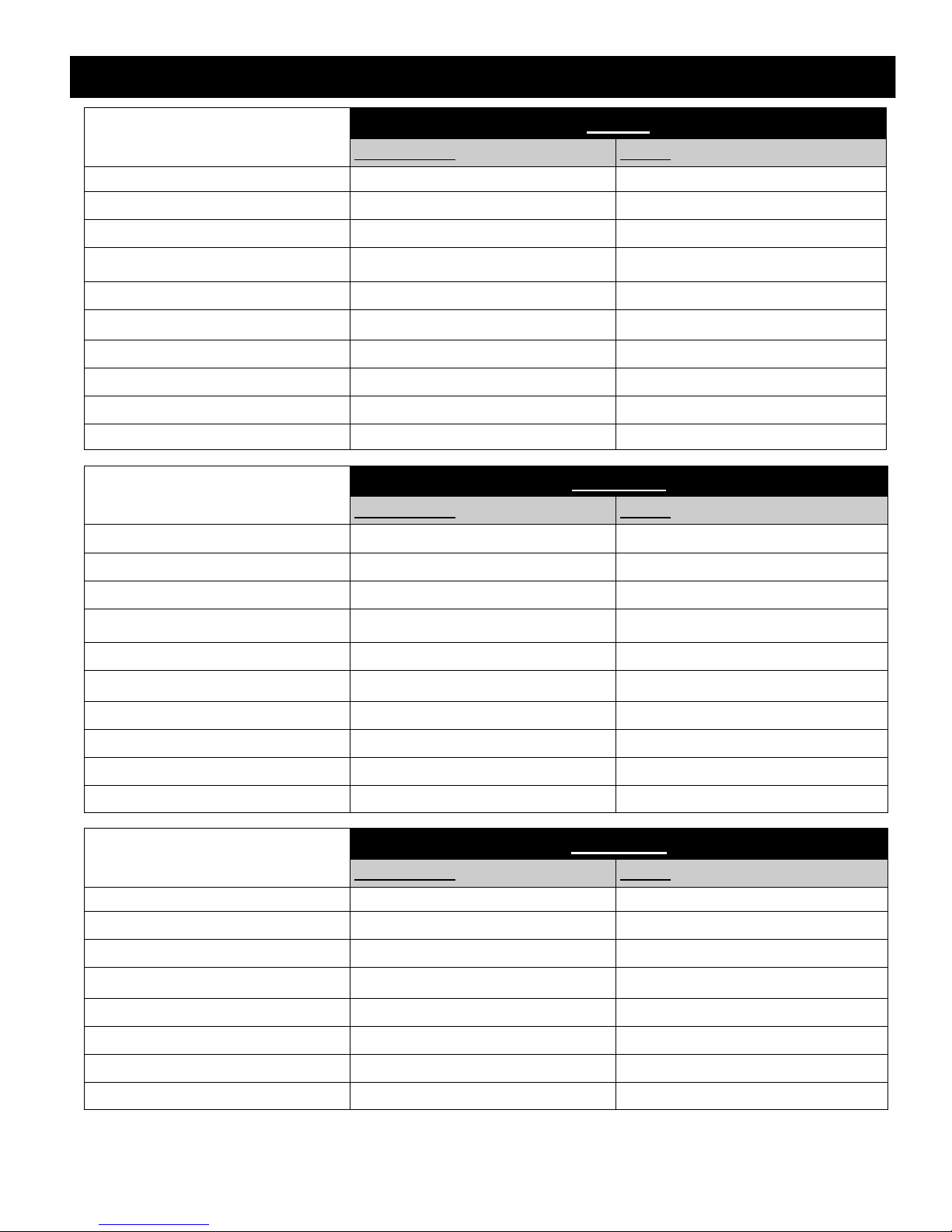
MINIMUM INLET GAS PRESSURE 5.0 inches W.C. (7.0 W.C. recommended) 11.0 inches W.C. (recommended)
MAXIMUM INLET GAS PRESSURE 10.5 inches W.C. 13.0 inches W.C.
MANIFOLD PRESSURE (HI) 3.5 inches W.C 10.0 inches W.C.
MANIFOLD PRESSURE (LO) 1.7 inches W.C. 6.3 inches W.C
ORIFICE SIZE #37 & #55 #52 & #71
INPUT BTU/hr. 35,000 34,800
MINIMUM INPUT BTU/hr. 22,500 25,500
EFFICIENCY 68.33% 71.81%
AFUE 67.69% 71.20%
P-4 AFE 54.77% 58.79%
NATURAL GAS LP GAS
PRC-36-RF
PRC-36
MINIMUM INLET GAS PRESSURE 5.0 inches W.C. (7.0 W.C. recommended) 11.0 inches W.C. (recommended)
MAXIMUM INLET GAS PRESSURE 10.5 inches W.C. 13.0 inches W.C.
NATURAL GAS LP GAS
MANIFOLD PRESSURE (HI) 3.5 inches W.C 10.0 inches W.C.
MANIFOLD PRESSURE (LO) 1.7 inches W.C. 6.3 inches W.C
ORIFICE SIZE #37 & #55 #52 & #71
INPUT BTU/hr. 35,000 34,800
MINIMUM INPUT BTU/hr. 22,500 25,500
EFFICIENCY 68.33% 71.81%
AFUE 67.69% 71.20%
P-4 AFE 54.77% 58.79%
PRC-36-IPI
MINIMUM INLET GAS PRESSURE 5.0 inches W.C. (7.0 W.C. recommended) 11.0 inches W.C. (recommended)
MAXIMUM INLET GAS PRESSURE 10.5 inches W.C. 13.0 inches W.C.
ORIFICE SIZE #37 & #55 #52 & #71
INPUT BTU/hr. 35,000 34,800
MINIMUM INPUT BTU/hr. 22,500 25,500
EFFICIENCY 68.33% 71.81%
NATURAL GAS LP GAS
AFUE 67.69% 71.20%
P-4 AFE 54.77% 58.79%
PAGE 20

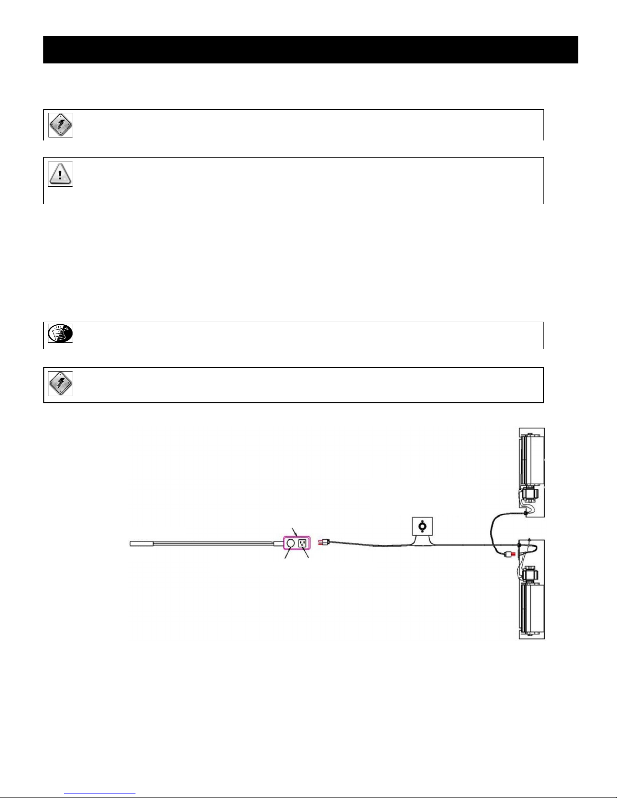
THERMOSTAT / WALL SWITCH / REMOTE (PRC-36 only)
If desired, a thermostat (wireless style also available), wall switch, or remote control assembly may be used to turn fireplace „OFF‟ and „ON‟. Only
ONE of these may be installed. Follow instructions included with each assembly.
NOTE: INSTALLATION OF THERMOSTAT OR WALL SWITCH SHOULD ONLY BE DONE BY A QUALIFIED INSTALLER.
CAUTION: DO NOT CONNECT HIGH VOLTAGE (115V) WIRE TO THE GAS VALVE!
Remote Control Wiring Diagram
Thermostat Wiring Diagram
OPTIONAL: Disconnect ON/OFF rocker
switch wires from back of gas valve.
WALL SWITCH / THERMOSTAT:
Run low-voltage (thermostat) wires from terminals on gas valve to desired location of wall switch or thermostat.
Attach appropriate connectors to wall switch / thermostat wires and connect to top and bottom terminals marked TH / TPTH on gas valve.
REMOTE CONTROL:
Follow instructions included with remote control.
IMPORTANT: If ON/OFF rocker switch wires are not disconnected, the ON/OFF rocker switch on millivolt board must be in „OFF‟ position for
proper operation of any of these components.
If rocker switch is „ON‟, fireplace burner will operate until it is turned „OFF‟ by rocker switch. A wall switch, thermostat, or remote control
will not turn fireplace „OFF‟ when it has been turned „ON‟ by the rocker switch.
NOTE: Fireplace must be turned „ON‟ and „OFF‟ by same method. For example: If fireplace is turned „ON‟ by remote control, it must be turned
„OFF‟ by remote control.
IMPORTANT: The insulated cover included with remote control must be placed over remote receiver to prevent overheating.
PAGE 21
VENTING
IMPORTANT: Consult the local and national installation codes to assure adequate combustion and ventilation air is available.
Refer to the vent systems manufacturer's installation manual for complete installation instructions.
Installation must conform with the venting requirements and restrictions as outlined in this manual.
Simpson Dura-Vent DV-GS 5” x 8” direct vent system (horizontal and vertical terminations).
Ameri-Vent Direct Chimney System 5” x 8” (horizontal and vertical terminations).
Metal Fab Direct Chimney System 5” x 8” (horizontal and vertical terminations).
ICC Direct Chimney Systems 5” x 8” (horizontal and vertical terminations).
Selkirk-Metalbestos Chimney Systems 5” x 8” (horizontal and vertical terminations).
Kozy Heat #800 series flexible vent system (horizontal terminations).
APPROVED VENTING
HORIZONTAL VENT SYSTEM CLEARANCES
ALL APPROVED VENTING
TOP BOTTOM SIDES
3 inches (76 mm) 1 inch (25 mm) 1 inch (25 mm)
VERTICAL VENT SYSTEM CLEARANCES
ALL APPROVED VENTING
TOP BOTTOM SIDES
1 inch (25 mm) 1 inch (25 mm) 1 inch (25 mm)
HORIZONTAL TERMINATIONS
MINIMUM: 45° elbow + 6” (152 mm) horizontal + termination cap.
MAXIMUM: OPTION #1: 45° elbow + 5 ft. (1.52 mm) + termination cap.
OPTION #2: 6” + 45˚ elbow + 10 ft. (3.05 m) + termination cap.
IMPORTANT: The horizontal vent heat shield must be installed when using a 45-degree elbow to horizontally position the vent system.
Exception: corner installations
Kozy Heat Wall Pass-thru, #800-WPT (4-1/2” (114 mm) - 6-1/2” (165 mm) wall thickness) or #800-WPT2 (6-1/2” (165 mm) - 12-1/2” (318 mm)
wall thickness), must be used on all horizontal vent runs.
RESTRICTOR
A restrictor is included in fireplace components packet.
Each installation is unique and affected by various factors including venting configuration, altitude and climate. Therefore, after
fireplace installation is complete a restrictor may be required or may need to be removed or modified.
Please refer to page 27 for installation instructions if installing restrictor in conjunction with venting.
Page 65 has information on restrictor recommendations depending on burner flame appearance and instructions on installation after
venting is completed.
ELBOWS
For each additional 90° elbow used after first elbow, 3 ft. (914 mm) must be subtracted from maximum allowed venting. For
each 45° elbow used, 1-1/2 ft. (457 mm) must be subtracted from maximum venting allowed.
NOTE: (2) 45° degree elbows may be used in place of (1) 90° elbow.
IMPORTANT: Flame height and appearance will vary depending upon venting configuration and type of fuel used.
Venting requirements apply to both Natural and LP gas.
PAGE 22
VENTING
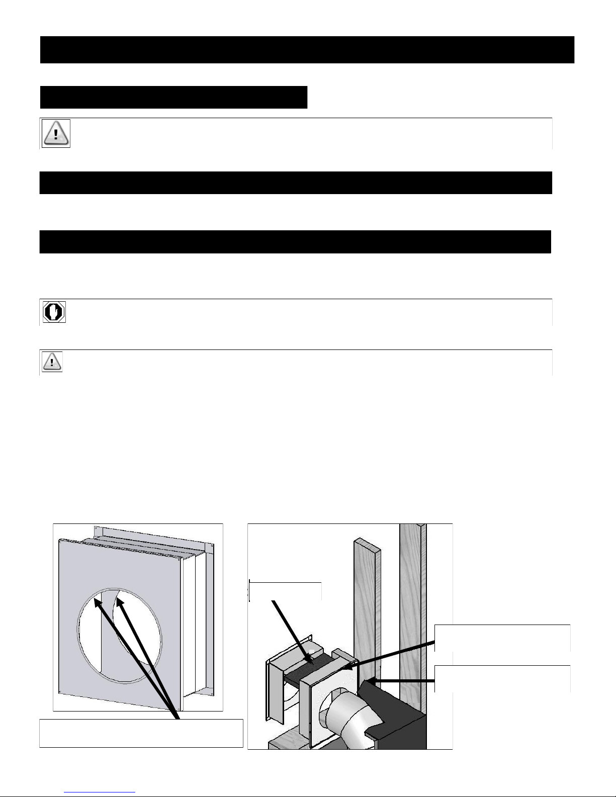
#800-WPT WALL PASS-THRU
IMPORTANT: #800-WPT or #800-WPT2 WALL PASS-THRU MUST BE USED ON ALL HORIZONTAL VENT TERMINATIONS. THIS INCLUDES
BOTH INTERIOR AND EXTERIOR WALLS. FOLLOW INSTRUCTIONS BELOW.
HORIZONTAL TERMINATIONS CLEARANCES
TOP: 3” (76 mm) SIDES & BOTTOM: 1” (25 mm)
FRAMING DIMENSIONS FOR #800-WPT KOZY HEAT WALL PASS-THRU
12-1/2” (318 mm) HIGH x 10-7/8” (276 mm) WIDE
WARNING: MAINTAIN ALL CLEARANCES AS STATED IN THIS INSTALLATION MANUAL.
IMPORTANT: If using Kozy Heat series flexible vent system, remove inner ring on each wall thimble section with a tin snips. This will
provide adequate room for the flexible vent system.
A. Measure wall thickness; cut insulation panel (included) this length.
B. Install wall pass-thru section marked #1 (with 3/8” (10 mm) flange) into framed opening. Secure to interior wall with screws
(not provided).
C. From the exterior, place insulation between flange and top of framed opening in wall pass-thru section #1.
D. Install section marked #2 of wall pass-thru into framed opening, overlapping metal sections as necessary to accommodate
wall thickness. Secure to exterior wall with screws (not provided).
INSULATION
3/8” (10 mm) FLANGE MUST BE
ON INSIDE WALL.
CUT RING OUT OF BOTH SECTIONS IF USING #800
SERIES FLEX VENTING.
HEAT SHIELD MUST BE FLUSH
WITH WALL PASS -THRU.
PAGE 23

VENTING (Horizontal)
HORIZONTAL TERMINATIONS
NOTE: Horizontal sections require 1/4” (6 mm) rise for every 12” (305 mm) of travel.
NOTE: Page 27 has information on restrictor installation in conjunction with venting installation. Page 65 has information on restrictor
recommendations depending on burner flame appearance and instructions on installation after venting is completed.
CAUTION: This gas appliance must not be connected to or joined with any other chimney flue serving another appliance.
IMPORTANT: The horizontal vent heat shield must be installed when using a 45-degree elbow to horizontally position the vent system.
Exception: corner installations
Kozy Heat Wall Pass-thru, #800-WPT (4-1/2” (114 mm) - 6-1/2” (165 mm) wall thickness) or #800-WPT2 (6-1/2” (165 mm) - 12-1/2” (318 mm) wall
thickness), must be used on all horizontal vent runs.
MINIMUM HORIZONTAL VENTING
HORIZONTAL VENT
HEAT SHIELD
45° ELBOW
TERMINATION CAP
MAXIMUM HORIZONTAL VENTING: OPTION #1
Horizontal vent heat shield not shown for clarity purposes only.
MAXIMUM HORIZONTAL VENTING: OPTION #2
6” (152 mm) VENT
PIPE SECTION
5 ft.
(1.52 m)
TERMINATION CAP 45° ELBOW
10 ft.
(3.05 m)
TERMINATION CAP 45° ELBOW
6” (152 mm) VENT
PIPE SECTION
PAGE 24

VENTING
HORIZONTAL TERMINATIONS
TYPICAL CORNER INSTALLATION
45° elbow + 90˚ elbow + horizontal pipe + termination cap.
VENTING DIMENSIONS FOR MINIMUM CORNER INSTALLATIONS
Vent Opening Dimensions: Refer to vent pipe manufacturer's instructions.
90° ELBOW
45° ELBOW
PIPE
HORIZONTAL
TERMINATION CAP
NOTE: Horizontal sections require 1/4” (6 mm) rise for every 12” (305 mm) of travel.
NOTE: Page 27 has information on restrictor installation in conjunction with venting installation. Page 65 has information on restrictor
recommendations depending on burner flame appearance and instructions on installation after venting is completed.
NOTE: Horizontal Vent Heat Shield not used in corner installations.
CAUTION: This gas appliance must not be connected to or joined with any other chimney flue serving another appliance.
IMPORTANT: The horizontal vent heat shield must be installed when using a 45-degree elbow to horizontally position the vent system.
Exception: corner installations
Kozy Heat Wall Pass-thru, #800-WPT (4-1/2” (114 mm) - 6-1/2” (165 mm) wall thickness) or #800-WPT2 (6-1/2” (165 mm) - 12-1/2” (318 mm) wall
thickness), must be used on all horizontal vent runs.
PAGE 25

VENTING
VERTICAL VENT SYSTEM CLEARANCES
ALL APPROVED RIGID PIPE
KOZY HEAT #800 SERIES
TOP BOTTOM SIDES
1 inch (25 mm) 1 inch (25 mm) 1 inch (25 mm)
DO NOT USE FOR VERTICAL TERMINATIONS
VERTICAL TERMINATIONS
MINIMUM: 45˚ elbow + 2 ft. (610 mm) + termination cap.
MAXIMUM: 45˚ elbow + 30 ft. (9.14 m) + termination cap.
NOTE: VERTICAL TERMINATIONS ONLY: The combustions air intake shield (located against lower back wall of firebox interior)
will require adjustment depending on venting height / configuration and type of fuel used. Use the chart below as a guideline
when adjusting to achieve desired flame appearance.
COMBUSTION AIR INTAKE SETTINGS
VERTICAL TERMINATION HEIGHT SETTING GAS TYPE
0 - 10 ft. (0 - 3.05 m ) 1 NAT
11 - 20 ft. (3.35 m - 6.10 m) 2 NAT
21 - 30 ft. (6.40 m - 9.14 m ) 3 NAT
25 - 30 ft. (7.62 m - 9.14 m) 4
NAT
RESTRICTOR
A restrictor is included in fireplace components packet.
Each installation is unique and affected by various factors including venting configuration, altitude and climate. Therefore, after
fireplace installation is complete a restrictor may be required or may need to be removed or modified.
Please refer to page 27 for installation instructions if installing the restrictor in conjunction with venting.
Page 65 has information on restrictor recommendations depending on burner flame appearance and instructions on installation after
venting is completed.
HORIZONTAL & VERTICAL COMBINATION TERMINATIONS
MAXIMUM: 10 ft. (3.05) horizontal + 15 ft. (4.57 m) vertical + cap. 25 ft (7.62m) total.
ELBOWS
For each additional 90° elbow used after first elbow, 3 ft. (914 mm) must be subtracted from maximum allowed venting.
For each 45° elbow used, 1-1/2 ft. (457 mm) must be subtracted from maximum venting allowed.
NOTE: (2) 45° degree elbows may be used in place of (1) 90° elbow.
IMPORTANT: The horizontal vent heat shield must be installed when using a 45-degree elbow to horizontally position the vent system.
Exception: corner installations
Kozy Heat Wall Pass-thru, #800-WPT (4-1/2” (114 mm) - 6-1/2” (165 mm) wall thickness) or #800-WPT2 (6-1/2” (165 mm) - 12-1/2” (318 mm) wall
thickness), must be used on all horizontal vent runs.
PAGE 26

VENTING (Vertical)
VERTICAL TERMINATIONS
MAXIMUM VERTICAL VENTING MINIMUM VERTICAL VENTING
TERMINATION CAP TERMINATION CAP
2 ft.”
(610 mm)
30 ft.
(9.14 m)
45° ELBOW
CAUTION: This gas appliance must not be connected to or
joined with any other chimney flue serving
another appliance.
RESTRICTOR INSTALLATION
TO BE USED AT INSTALLER DISCRETION.
45° ELBOW
Large Restrictor
NOTE: Page 65 has information on restrictor recommendations
depending on burner flame appearance and instructions on
installation after venting is completed.
Remove tab (s) to create
small restrictor
Bend tabs to approx. 80 degree
angles to create tension to hold
itself in place when installed.
PAGE 27
Slide restrictor into exhaust pipe on top of fireplace with
tabs pointing towards you prior to attaching venting.

HORIZONTAL / VERTICAL COMBINATION:
(4.57m) 15' Vertical
(3.05m) 10' Horizontal
Termination must be
within shaded area
(ft.)
0
2
4
6
8
10
12
14
16
20
22
18
24
26
28
30
40
38
36
34
32
10 12 14 16 18 20 22 24 26 28 30
(6.1m)
(6.1m)
(12.9m)
(9.14m)
0 2
4
6 8
VENTING (Horizontal & Vertical Combination)
CAUTION: This gas appliance must not be connected to or joined with any other chimney flue serving another appliance.
Horizontal sections require 1/4” (6 mm) rise for every 12” (305 mm) of travel.
For each additional elbow used after the first elbow, 3 ft. (914 mm) must be subtracted from the maximum venting allowed. For each 45° elbow used, 1-1/2 ft.
(457 mm) must be subtracted from the maximum venting allowed.
(2) 45° degree elbows may be used in place of (1) 90° elbow.
NOTE: Page 27 has information on restrictor installation in conjunction with venting installation.
Page 65 has information on restrictor recommendations depending on burner flame appearance and instructions on installation after
venting is completed.
IMPORTANT: The horizontal vent heat shield must be installed when using a 45-degree elbow to horizontally position the vent system.
Exception: corner installations
Kozy Heat Wall Pass-thru, #800-WPT (4-1/2” (114 mm) - 6-1/2” (165 mm) wall thickness) or #800-WPT2 (6-1/2” (165 mm) - 12-1/2” (318 mm) wall
thickness), must be used on all horizontal vent runs.
PAGE 28
VENTING (Flexible (#800 Series)
INSTALLATION OF #800 SERIES DIRECT VENT TERMINATION KIT(S)
IMPORTANT: The flex pipe is permanently attached to the exterior plate. DO NOT ATTACH #844 or #845 termination kit to
fireplace (or extension kit ) until it has passed through wall. Install termination plates to outside wall exterior.
HORIZONTAL TERMINATIONS Refer to illustration on following page.
IF TERMINATING AGAINST VINYL SIDING, A VINYL SIDING PROTECTOR, INCLUDED WITH #844 AND #845 DIRECT
VENT KITS, MUST BE USED. FOLLOW INSTRUCTIONS INCLUDED.
IMPORTANT: The Kozy Heat wall pass-thru, part #800-WPT or #800-WPT2, must be used on all horizontal vent applications
regardless of which vent system you are using.
CAUTION: This gas appliance must not be connected to a chimney flu serving another type of appliance.
NOTE: Page 27 has information on restrictor installation in conjunction with venting installation. Page 65 has information on
restrictor recommendations depending on burner flame appearance and instructions on installation after venting is
completed.
1. If your vent system application does not require an extension kit, proceed to step #7.
2. If your vent system application will require one or more extension kits (Part #846), proceed with the following steps. Each #846
extension kit contains enough 5” & 8” flexible aluminum to extend chimney an additional 6‟ (1.83 m).
3. Gently stretch 5” & 8” flexible aluminum pipes on termination kit (#844 or #845) and on each extension kit (if used) the length
required for your installation.
IMPORTANT: DO NOT STRETCH EXTENSION KIT BEYOND 6‟ (1.83 m). DO NOT STRETCH BEYOND WHAT IS
REQUIRED - IT IS VERY DIFFICULT TO RECOMPRESS THE FLEX PIPES ONCE STRETCHED.
4. Place a bead of sealant outside 5” flex pipe collar (C) (end with EXTERNAL lip), sliding it inside 5” pipe on top of fireplace (D).
Secure with 3 evenly spaced screws.
5. Place a bead of sealant inside 8” flex pipe collar (E) (end with the INTERNAL lip), sliding it over 8” pipe on top of fireplace (F).
Secure with 3 evenly spaced screws.
6. If additional extension kits are required, repeat steps #4 - #5, placing 5” & 8” pipes onto previous extension kit.
7. With spacer legs toward the wall, slide interior firestop (H) over 8” pipe and attach tointerior wall (over wall materials).
NOTE: Attachment brackets are included with termination kit. These optional brackets should be screwed or nailed (not
provided) onto the top and bottom of 9-1/2” (241 mm) H x 9-1/2” (241 mm) W opening on exterior of house. The
termination plates then fit between these brackets. Using screws provided, secure brackets to termination box (A).
Attach vinyl siding protector (G).
8. Apply a liberal bead of exterior sealant around outer edge of termination box (A), placing assembly through opening in exterior
wall. Place screws through four slots (B), securing it in place.
9. Gently pull 5” & 8” pipes down to top of extension kit, or top of fireplace if no extension kits were used.
10. Place a bead of sealant outside 5” flex pipe collar (C) and slide it into 5” pipe on extension kit or top of fireplace (D).
Secure with 3 evenly spaced screws.
PAGE 29

VENTING (Flexible #800 Series cont)
11. Place a bead of sealant inside 8” flex pipe collar (E) and slide it over 8” pipe on extension kit or top of fireplace (F). Secure with
3 evenly spaced screws.
12. OPTIONAL: Place insulation between 8” pipe and wall studs.
A TERMINATION BOX
B SLOTS IN EXTERIOR WALL PLATE
C 5” FLEX PIPE COLLAR
5” PIPE ON FIREPLACE OR
D
EXTENSION KIT
E 8” FLEX PIPE COLLAR
8” PIPE ON FIREPLACE OR
F
EXTENSION KIT
G
A
G VINYL SIDING PROTECTOR
H INTERIOR FIRESTOP
H
B
E
C
D
F
PAGE 30

B
B
L
DENOTES WHERE INSTALLATION NOT ALLOWED
J
K
C
G
P
H
I
O
D
E
A
N
F
M
TERMINATION VENT CAP LOCATION
This gas appliance must not be connected to a chimney serving any other appliance.
1. Terminations against vinyl siding must use a vinyl siding protector. Follow instructions included.
2. DO NOT RECESS TERMINATION KIT INTO OUTSIDE BUILDING MATERIALS - i.e.: brick, stone, siding, etc.
If necessary, extend framing so that termination kit will be exposed once building materials are installed.
3. Vent termination must not be located where it will become plugged by snow or other material. The flow of combustion
and ventilation air must be not obstructed.
LOCATION CLEARANCES
A. Above grade, veranda, porch, deck, balcony - 12" (305 mm).
B. Operable window or door - CANADA: 12" (305 mm). US: 9” (229 mm).
C. Permanently closed window* - 12" (305 mm) (recommended to prevent condensation on window).
D. Ventilated soffit* - 24" (610 mm).
E. Unventilated soffit* - 12" (305 mm).
F. Outside corner* - 12" (305 mm).
G. Inside corner* - 12” (305 mm).
H. Meter / Regulator: Not to be installed above a gas meter/regulator assembly within 3 ft. (914 mm) horizontally from
the centerline of the regulator.
I. Gas Service regulator vent outlet - 3 ft. (914 mm).
J. Non-mechanical air supply inlet to building or the combustion air inlet to any other appliance. CANADA: 12" (305 mm).
US: 9” (229 mm).
K. Mechanical air supply inlet. CANADA: 6 ft. (1.83 m) US: 3 ft. (914 mm) above if within 10 ft. (3.05 m) horizontally.
Massachusetts installations: 10 ft. (3.05 m).
L. Above paved side-walk or paved driveway located on public property - 7 ft. (2.13 m).
NOTE: A vent cannot be located directly above a side-walk or paved driveway that is located between two single family dwellings
and serves both dwellings.
M. Under veranda, porch, deck, or balcony (must be fully opened on a min. of 2 sides) - 12" (305 mm).
N. Between two horizontal terminations - 12" (305 mm).
O. Between two vertical terminations - 12" (305 mm). Terminations may be the same height.
P. Above furnace exhaust or inlet - 12" (305 mm).
*Clearance must be in accordance with local installation codes & the requirements of the gas supplier.
PAGE 31

VENTING (Vertical Cap Requirements)
H
12
X
ROOF PITCH = X/12
H (minimum) - MINIMUM HEIGHT FROM ROOF
TO LOWEST DISCHARGE OPENING
APPROVED CAP
APPROVED VENT PIPE
DISCHARGE OPENING
*8' MIN
* - IF VENT IS CLOSER THAN 8', IT MUST
TERMINATE AT LEAST 2' HIGHER THAN ANY
PORTION OF A BUILDING WITHIN 10' OF THE VENT
VENT TERMINATION CLEARANCES
Roof Pitch H (Min.) Ft. H (Min.) m
Flat to 6/12 1.0 0.30
Over 6/12 to 7/12 1.25 0.38
Over 7/12 to 8/12 1.5 0.46
Over 8/12 to 9/12 2.0 0.61
Over 9/12 to 10/12 2.5 0.76
Over 10/12 to 11/12 3.25 0.99
Over 11/12 to 12/12 4.0 1.22
Over 12/12 to 14/12 5.0 1.52
Over 14/12 to 16/12 6.0 1.83
Over 16/12 to 18/12 7.0 2.13
Over 18/12 to 20/12 7.5 2.27
Over 20/12 to 21/12 8.0 2.44
CAUTION: This appliance must not be connected to or joined with any chimney flue serving any other appliance.
*(2.44 m)
* IF VENT IS CLOSER THAN 8’ (2.44 m), IT MUST TERMINATE AT
LEAST 2’ (0.61 m) HIGHER THAN ANY PORTION OF A BUILDING
WITHIN 10’ (3.05 m) OF THE VENT.
PAGE 32

#MTK-BLK Back Light Kit (PRC-36-IPI standard)
NOTE: #MTK-BLK Back Light Kit comes standard with #PRC-36-IPI models.
This light kit is available as an optional accessory for models #PRC-36 and #PRC-36-RF. See your dealer for details.
ATTENTION: If converting to LP (propane) gas, do so now before installing light kit components. Follow instructions included with
conversion kit.
CAUTION: Disconnect all electrical power from fireplace before performing this task.
1. Remove light cylinders from back of burner assembly.
NOTE: To prolong the life of halogen bulbs and avoid damage, never
touch bulbs with bare hands. Always use a soft cloth when
handling.
2. Locate (2) 35 Watt 120V Halogen Bulbs in fireplace components
packet. Install halogen bulbs into receptacles.
3. Reinstall light cylinders (with flared end up) over light stands and
through holes in burner until resting on light stand tabs.
4. Locate (2) Amber Colored Light Filters in fireplace
components packet. Install one into each light cylinder.
PAGE 33

LOG SET INSTALLATION
ATTENTION: If converting to LP (propane) gas, do so now before installing log set. Follow instructions included with conversion kit.
NOTE: Log numbers are located on the bottom of each log. Refer to following instructions and illustrations for proper placement.
CAUTION: Do not place logs directly over burner port holes. Improper log placement may affect flame appearance and cause excessive
soot to build up on logs and glass.
STEP 1
#P1
Position log #P1 over pilot shield, pulling log forward until it reaches backside of burner ports.
STEP 2
#P2
#P3
Position logs #P2 & #P3 onto burner as shown above.
PAGE 34

LOG SET INSTALLATION
STEP 3
#M6
#P4
STEP 4
Position #M6 (2) and #P4 logs onto burner as shown above.
#P9
#P8
Position logs #P8 & #P9 onto base logs and log grate. The #P8 log is placed over burner jumper tube.
PAGE 35

LOG SET INSTALLATION
STEP 5
#P7
#P6
#P5
Install logs #P5 - #P7 as shown.
Use a steel or stiff bristle nylon brush to distribute Rock Wool Embers onto logs and burner.
Randomly place „Klinkers‟ in this area. Do not place „Klinkers‟ directly on burner ports.
PAGE 36

MILLIVOLT BOARD REMOVAL
CAUTION: If burner and/or pilot have been burning, use appropriate protection to avoid burns or damage to personal property before
removing any components.
1. Models PRC-36 & PRC-36-RF: Turn gas control knob to „OFF‟.
Model PRC-36-IPI: Use remote to turn fireplace off.
2. Shut off gas supply at manual shut-off valve.
3. Disconnect gas line flex tube from manual shut-off valve.
4. Model PRC-36: Disconnect any wall switch, remote control or
thermostat wires from top & bottom terminals on gas valve.
Model PRC-36-RF: Unplug fan cord from receptacle, disconnect
(2) wires from fan cord. (Wires will remain connected to back of
gas valve).
Model PRC-36-IPI: Unplug all components from electrical outlet, disconnect all wiring harnesses attached to gas valve.
5. Remove upper hood, upper louver.
6. Remove glass assembly.
7. Remove logs, pilot shield and ember log refractory.
8. Remove pilot shield.
Model PRC-36-IPI:
Remove light cylinders, amber light filters, and halogen bulbs.
9. Remove screws securing front left and back right log grate legs.
Remove burner/log grate assembly from firebox by lifting front of
burner assembly up out of flange while pushing pilot assembly
back slightly.
10. Remove screws securing front burner assembly. Remove front
burner assembly.
11. Remove adjustable venturi mounting spacers.
Model PRC-36-IPI:
Remove screws securing light stands. Carefully push stands off
millivolt board.
12. Remove (8) screws securing millivolt board. Lift board up and out
of firebox.
BURNER LOG GRATE ASSEMBLY
PILOT SHIELD
REMOVE (2) SCREWS
REMOVE (2) SCREWS
REMOVE (8) SCREWS
FRONT BURNER ASSEMBLY
PAGE 37

MILLIVOLT BOARD INSTALLATION
WARNING: DO NOT OPERATE THIS FIREPLACE WITHOUT SEALING GASKET (LOCATED UNDER MILLIVOLT BOARD) IN PLACE.
IF GASKETING IS DAMAGED, IT MUST BE REPLACED.
1. Place millivolt board in firebox, aligning holes in millivolt board with holes in
firebox bottom. MAKE SURE SEALING GASKET IS IN PLACE ON FIREBOX BOTTOM! Secure millivolt board to firebox bottom with (8) screws
previously removed.
2. Place venturi spacers onto venturi mounting studs.
Model PRC-36-IPI:
Reinstall light stands with screws previously removed.
3. Re-install front burner assembly, making sure burner tube is positioned over
burner orifice. Secure with screws.
4. Reinstall back burner/log grate assembly by positioning burner tube into venturi collar on millivolt board and pilot assembly through rectangular opening.
Secure front left and back right legs with screws.
5. Reinstall pilot shield.
6. Reinstall ember refractory.
Model PRC-36-IPI:
Reinstall halogen bulbs, light cylinders and amber light filters.
7. Reinstall log set. (Pages 34-36).
8. Reconnect gas line to manual shut-off valve.
9. Model PRC-36: Reconnect any wall switch, remote control or thermostat
wires to top & bottom terminals on gas valve.
Model PRC-36-RF: Re-connect the (2) wires to fan cord. Plug fan cord into
receptacle.
Model PRC-36-IPI: Re-connect all wiring harnesses to gas valve. Plug all
components into electrical outlet.
10. Reinstall glass frame assembly. Page 16.
11. Reinstall upper louver & upper hood. Page 39.
12. Turn gas on.
13. Verify proper log placement, operation of fireplace, and any electrical
components.
CAUTION: CHECK ALL CONNECTIONS FOR LEAKS, WHETHER
FIELD OR FACTORY MADE.
INSTALL (8) SCREWS
INSTALL (2) SCREWS
INSTALL (2) SCREWS
BURNER LOG GRATE ASSEMBLY PILOT SHIELD
FRONT BURNER ASSEMBLY
RE-CONNECT ANY REMOTE /
THERMOSTAT WIRES
PAGE 38

GRILL SET
UPPER LOUVER, HOOD & LOWER GRILL INSTALLATION & REMOVAL
INSTALLATION
Slide flange on upper
hood into clips in top
of upper air passage
opening.
Upper hood clips
A. Align hooks in upper louver to slots located in fireplace face.
Set down into position.
Thread screws into nuts on each end of grill
and secure to lower grill opening.
C. Partially thread (2) screws (included in components packet) into
nuts at each end of lower grill. Secure to fireplace by threading
screws into corresponding holes in inside flange of lower grill
opening. The lower grill can now be opened and closed to access
gas valve and controls.
B. Insert upper hood flange into clips located at top of upper air
passage.
NOTE: THIS IS A FAIRLY TIGHT FIT.
REMOVAL
A. Use both hands to pull hood out of upper air passage clips.
B. Lift upper louver up and out of slots.
C. Remove screws securinglower grill at each end to remove from
fireplace.
PAGE 39

PRC-36 VALVE & PILOT ASSEMBLY COMPONENTS
ELECTRODE
PILOT HOOD
PILOT SHIELD
THERMOPILE
THERMOCOUPLE
HI /LO FLAME ADJUSTMENT KNOB
VALVE TERMINALS
GAS CONTROL KNOB PIEZO IGNITOR
ON/OFF ROCKER SWITCH
PAGE 40

PRC-36 LIGHTING AND SHUTDOWN
FOR YOUR SAFETY - READ BEFORE LIGHTING
WARNING: IF YOU DO NOT FOLLOW THESE INSTRUCTIONS EXACTLY, A FIRE OR EXPLOSION MAY RESULT, CAUSING
PROPERTY DAMAGE, PERSONAL INJURY OR LOSS OF LIFE.
DUE TO HIGH SURFACE TEMPERATURES, KEEP CHILDREN, CLOTHING AND FURNITURE AWAY.
This appliance needs fresh air for safe operation and must be installed so there are provisions for adequate combustion and ventilation air.
1. This appliance has a pilot which must be lighted by hand. When lighting
the pilot, follow these instructions exactly.
2. BEFORE LIGHTING, smell all around the appliance for gas. Be sure to
smell next to the floor because some gas is heavier than air and will
settle on the floor.
3. Use only your hand to push in or turn the gas control knob. Never use
tools. If the knob will not push in, or turn by hand, do not try to repair it,
call a qualified service technician. Forced or attempted repair may result
in a fire or explosion, and loss of warranty.
4. Do not use this appliance if any part has been under water.
Immediately call a qualified service technician to inspect the appliance
and to replace any part of the control system which has been under
water.
DO NOT STORE OR USE GASOLINE OR OTHER
FLAMMABLE VAPORS AND LIQUIDS IN THE
VICINITY OF THIS OR ANY OTHER APPLIANCE.
WARNING: CHILDREN AND ADULTS SHOULD BE ALERTED TO THE HAZARDS OF HIGH SURFACE TEMPERATURES
AND SHOULD STAY AWAY TO AVOID BURNS OR CLOTHING IGNITION. YOUNG CHILDREN SHOULD BE
CAREFULLY SUPERVISED WHEN THEY ARE IN THE SAME ROOM AS THE APPLIANCE. CLOTHING OR
OTHER FLAMMABLE MATERIAL MUST NOT BE PLACED ON OR NEAR THE APPLIANCE.
WHAT TO DO IF YOU SMELL GAS:
Do not touch any electrical switches
Do not try to light any appliance
Do not use the phone in your building
Immediately call your gas supplier from a neighbor‟s
phone
Follow the gas supplier‟s instructions
If you cannot reach your gas supplier, call the fire department
NOTE: A PAINT SMELL WILL OCCUR DURING THE FIRST FEW HOURS OF BURNING. IT IS RECOMMENDED TO
LEAVE THE FAN OFF DURING THIS PERIOD TO HELP SPEED THE PAINT CURING PROCESS.
NOTE: THIS FIREPLACE MAY PRODUCE NOISES OF VARYING DEGREE AS IT HEATS AND COOLS DUE TO METAL
EXPANSION AND CONTRACTION. THIS IS NORMAL AND DOES NOT AFFECT THE PERFORMANCE OR
LONGEVITY OF THE FIREPLACE.
PAGE 41

PRC-36 LIGHTING AND SHUTDOWN (cont.)
LIGHTING
1. Set thermostat to lowest setting, if installed.
2. Turn off all electrical power to appliance. (Fan).
3. Open lower grill to access gas valve & controls.
A. Push gas control knob in slightly and turn
clockwise to “OFF”. Wait five (5) minutes to allow
any gas that may have accumulated inside firebox to
escape. If you then smell gas, STOP! Follow safety
information on previous page and front cover of this
installation manual. If you don‟t smell gas, go to next
step.
NOTE: Gas control knob cannot be turned from
“PILOT” to “OFF” unless knob is pushed
in slightly. Do not force.
B. Locate pilot - follow metal tube from gas control. The
pilot is located inside the combustion chamber.
C. Push gas control knob on gas valve in slightly and
turn counterclockwise to „PILOT‟. Push valve knob in
and hold while repeatedly pressing the piezo igniter
button until pilot is lit, while continuing to hold in gas
control knob.
D. Hold gas control knob in for one (1) minute after pilot
is lit. Release gas control knob. If pilot goes out,
repeat steps C-D. When pilot is lit, proceed to step E.
CAUTION: If knob does not pop up when released,
stop and immediately call your service
technician or the gas supplier. If pilot
will not stay lit after several tries, turn
gas control knob to OFF and call your
service technician or gas supplier.
C
A
D
B
5 MINUTES
PILOT
PILOT TUBE
1 MINUTE
E. Push gas control knob in slightly and turn counter-
clockwise to „ON‟. The burner can now be turned
„ON‟ by depressing ON/OFF rocker switch located
beside valve, or wall switch, OR by setting thermostat
or remote control to desired setting.
F. Turn on all electric power to appliance (if applicable).
NOTE: When fireplace is initially lit, condensation
will appear on the glass; this is normal in all
gas fireplaces and will disappear after
several minutes.
E
PAGE 42

PRC-36 LIGHTING AND SHUTDOWN (cont.)
TURN BURNER OFF
G. To turn burner „OFF‟, depress ON/OFF rocker switch to „OFF‟, flip
„off‟ wall switch or adjust setting on thermostat or remote control.
NOTE: The pilot will stay lit.
TURN PILOT OFF
H. Turn pilot off by pushing in and turning the gas control knob to „OFF‟
position. DO NOT FORCE.
NOTE: This control valve has an interlock device. If pilot has been
turned off, it cannot be relit until the thermocouple has
cooled, (approximately 60 seconds).
G
H
ADJUSTING FLAME HEIGHT
The gas control valve has a HI /LO flame adjustment knob designed to allow
you to tailor the look and heat output of your fireplace. Adjust by turning
middle knob ongas control valve.
PAGE 43

PRC-36 PRESSURE TESTING
IMPORTANT NOTICE: Pressure check taps for the manifold (outgoing) and inlet (incoming) pressure have been incorporated into the
valve. The pressure tap marked „OUT‟ measures outgoing pressure and the pressure tap marked „IN‟ measures
incoming pressure. Follow instructions below for proper testing procedures.
NOTE: The appliance and its individual shutoff valve must be disconnected from the gas supply piping system during any pressure
testing of that system at pressures in excess of ½ psi.
NOTE: The appliance must be isolated from the gas supply piping system by closing its individual manual shut-off valve during any
pressure testing of the gas line at test pressures equal to or less than ½ psi (3.5 kPa).
INLET PRESSURE TEST:
1. Loosen inlet („IN‟) pressure tap screw (counter-clockwise).
2. Attach manometer using a 5/16” I.D. hose.
3. Light pilot.
4. Turn gas control knob to „ON‟ (burner should not light). Note manometer reading.
5. Press rocker switch to „ON‟. Check pressure to ensure that it stays near the maximum inlet pressure.
6. Press rocker switch to „OFF‟.
7. Turn gas control knob to „OFF‟.
8. Disconnect hose and tighten screw (clockwise). Screw should be snug, do not over tighten.
9. Relight pilot and turn gas control knob to „ON‟. Reattach manometer to inlet pressure tap to verify that it is
completely sealed. Manometer should read no pressure.
NOTE: If inlet pressure reading is too high or too low, contact the gas company. Only a qualified gas service technician should adjust
incoming gas pressure.
MANIFOLD PRESSURE TEST:
1. Light pilot.
2. Loosen manifold („OUT‟) pressure tap screw (counter-clockwise).
3. Attach manometer to pressure tap using a 5/16” I.D. hose.
4. Turn gas control knob to „ON‟.
5. Press rocker switch to „ON‟ and note manometer reading.
6. Press rocker switch to „OFF‟.
7. Disconnect manometer hose and tighten screw (clockwise). Screw should be snug, do not over tighten.
8. Attach manometer to manifold pressure tap to verify that it is completely sealed. Manometer should read no pressure when the
rocker switch is pressed to „ON‟.
MANIFOLD
CAUTION: A LOW PRESSURE READING CAN
CAUSE DELAYED IGNITION.
INLET
PAGE 44

PRC-36-RF VALVE & PILOT ASSEMBLY COMPONENTS
INLET
PRESSURE
OUTLET
PRESSURE
TAP
MOTOR
TAP
GAS CONTROL
KNOB
PIEZO
PILOT
ADJUSTMENT
SCREW
MOTOR
COVER
LED
RF VALVE (bottom view)
WIRING
TERMINALS
FAN
TERMINALS
WHITE
DOTS
FUEL CONVERSION
PLUG
PILOT
THERMOPILE
ELECTRODE
THERMOPILE
ANTENNA
WHITE
RED
PAGE 45

PRC-36-RF LIGHTING AND SHUTDOWN
FOR YOUR SAFETY - READ BEFORE LIGHTING
WARNING: IF YOU DO NOT FOLLOW THESE INSTRUCTIONS EXACTLY, A FIRE OR EXPLOSION MAY RESULT, CAUSING
PROPERTY DAMAGE, PERSONAL INJURY OR LOSS OF LIFE.
DUE TO HIGH SURFACE TEMPERATURES, KEEP CHILDREN, CLOTHING AND FURNITURE AWAY.
This appliance needs fresh air for safe operation and must be installed so there are provisions for adequate combustion and ventilation air.
1. This appliance has a pilot which must be lighted by hand. When lighting
the pilot, follow these instructions exactly.
2. BEFORE LIGHTING, smell all around the appliance for gas. Be sure to
smell next to the floor because some gas is heavier than air and will
settle on the floor.
3. Use only your hand to push in or turn the gas control knob. Never use
tools. If the knob will not push in, or turn by hand, do not try to repair it,
call a qualified service technician. Forced or attempted repair may result
in a fire or explosion, and loss of warranty.
4. Do not use this appliance if any part has been under water.
Immediately call a qualified service technician to inspect the
appliance and to replace any part of the control system which has been
under water.
DO NOT STORE OR USE GASOLINE OR OTHER
FLAMMABLE VAPORS AND LIQUIDS IN THE
VICINITY OF THIS OR ANY OTHER APPLIANCE.
WARNING: CHILDREN AND ADULTS SHOULD BE ALERTED TO THE HAZARDS OF HIGH SURFACE TEMPERATURES
AND SHOULD STAY AWAY TO AVOID BURNS OR CLOTHING IGNITION. YOUNG CHILDREN SHOULD BE
CAREFULLY SUPERVISED WHEN THEY ARE IN THE SAME ROOM AS THE APPLIANCE. CLOTHING OR
OTHER FLAMMABLE MATERIAL MUST NOT BE PLACED ON OR NEAR THE APPLIANCE.
WHAT TO DO IF YOU SMELL GAS:
Do not touch any electrical switches
Do not try to light any appliance
Do not use the phone in your building
Immediately call your gas supplier from a neighbor‟s
phone
Follow the gas supplier‟s instructions
If you cannot reach your gas supplier, call the fire department
NOTE: A PAINT SMELL WILL OCCUR DURING THE FIRST FEW HOURS OF BURNING. IT IS RECOMMENDED TO
LEAVE THE FAN OFF DURING THIS PERIOD TO HELP SPEED THE PAINT CURING PROCESS.
NOTE: THIS FIREPLACE MAY PRODUCE NOISES OF VARYING DEGREE AS IT HEATS AND COOLS DUE TO METAL
EXPANSION AND CONTRACTION. THIS IS NORMAL AND DOES NOT AFFECT THE PERFORMANCE OR
LONGEVITY OF THE FIREPLACE.
PAGE 46

PRC-36-RF LIGHTING AND SHUTDOWN (cont.)
LIGHTING
1. Turn off all electrical power to appliance. (Fan).
2. Open lower grill to access gas valve & controls.
A. Push control knob in slightly and turn clockwise to the
OFF position. Wait five (5) minutes to clear out any
gas. If you then smell gas, STOP! Follow safety information on previous page and on front cover of this in-
stallation manual. If you don‟t smell gas, go to the next
step.
B. Locate pilot. The pilot is located inside the combustion
chamber.
C. Push control knob on gas valve in slightly and turn
counterclockwise to PILOT. Push control knob all the
way in and hold. Push plunger on piezo ignitor until
pilot is lit. The pilot will generally light within two or
three pushes on the piezo ignitor. Hold knob for about
one (1) minute after pilot is lit. Release knob and it will
pop back out. Pilot should remain lit. If it goes out,
repeat steps A-C.
5 MINUTES
A.
B.
1 MINUTE
CAUTION: If knob does not pop up when released, stop and
immediately call your service technician or the gas
supplier. If pilot will not stay lit after several tries,
turn gas control knob to OFF and call your service
technician or the gas supplier.
NOTE: Gas control knob cannot be turned from “PILOT” to “OFF”
unless knob is pushed in slightly. Do not force.
D. Push control knob on gas valve in slightly
and turn counterclockwise to ON.
NOTE: If the manual switch is in LOCAL , the main burner will turn
on immediately.
NOTE: When fireplace is initially lit, condensation will appear on the
glass; this is normal in all gas fireplaces and will disappear
after several minutes.
C.
D.
PAGE 47

PRC-36-RF LIGHTING AND SHUTDOWN (cont.)
INITIAL USE OF TRANSMITTER
IMPORTANT: Upon initial use of transmitter, a recognition
operation is required between receiver/valve
and transmitter.
1. Turn gas control knob to PILOT.
Move LOCAL / REMOTE switch to
LOCAL for at least two (2) seconds,
then move switch to REMOTE.
2. Press FAN or FLAME button on
transmitter within thirty (30) seconds
of switch change.
3. Turn gas control knob to ON position.
1.
WITHIN
30 SECONDS
OR PRESS
2.
2 SECONDS
The LED will blink, indicating transmitter will now work with
receiver / valve. If switch stays in REMOTE the TR8220A
Transmitter will control main valve, flame modulation level and
fan control.
If LOCAL / REMOTE switch is in LOCAL, the receiver /
valve will be at highest setting.
TURN THE BURNER OFF
LOCAL SETTING: Turn control knob clockwise to PILOT.
REMOTE SETTING: The TR8220A transmitter can shut off
the main burner and fan. However, the control is still „ON‟ and a
command from transmitter can turn on main burner and fan.
TURN THE SYSTEM OFF
1. Open lower grill to access gas valve & controls.
2. Turn gas control knob clockwise to OFF. This closes main
gas and safety valves. The transmitter cannot turn “ON”
main burner or fan.
3.
NOTE: If manual switch is in LOCAL, the main burner
will turn on immediately.
NOTE: This control valve has an interlock device. If
pilot has been turned off, it cannot be relit until
the thermocouple has cooled, (approximately
60 seconds).
PAGE 48

PRESSURE TESTING (PRC-36-RF)
IMPORTANT NOTICE: Pressure check taps for the manifold (outgoing) and inlet (incoming) pressure have been incorporated into the
valve. The pressure tap marked „OUT‟ measures outgoing pressure and the pressure tap marked „IN‟
measures incoming pressure. Follow instructions below for proper testing procedures.
NOTE: The appliance and its individual shutoff valve must be disconnected from the gas supply piping system during any
pressure testing of that system at pressures in excess of ½ psi.
NOTE: The appliance must be isolated from the gas supply piping system by closing its individual manual shut-off valve during
any pressure testing of the gas line at test pressures equal to or less than ½ psi (3.5 kPa).
INLET PRESSURE TEST:
1. Loosen inlet („IN‟) pressure tap screw (counter-clockwise).
2. Attach manometer using a 1/4” I.D. hose.
3. Light pilot.
4. Turn gas control knob to „ON‟. Note manometer reading.
5. Turn gas control knob to „OFF‟.
6. Disconnect hose and tighten screw (clockwise). Screw should be snug, do not over tighten.
9. Relight pilot and turn gas control knob to „ON‟. Reattach manometer to inlet pressure tap to verify that it is completely sealed.
NOTE: If inlet pressure reading is too high or too low, contact the gas company. Only a qualified gas service technician should adjust
the incoming gas pressure.
MANIFOLD PRESSURE TEST:
1. Light pilot.
2. Loosen manifold („OUT‟) pressure tap screw (counter-clockwise).
3. Attach manometer to pressure tap using a 1/4” I.D. hose.
4. Turn gas control knob to „ON‟. Note manometer reading.
5. Disconnect manometer hose and tighten screw (clockwise). Screw should be snug, do not over tighten.
6. Attach manometer to manifold pressure tap to verify that it is completely sealed. Manometer should read no pressure.
CAUTION: A LOW PRESSURE READING CAN
CAUSE DELAYED IGNITION
PAGE 49

PRC-36-RF REMOTE RECEIVER FUNCTIONS
IMPORTANT: PLEASE REVIEW AND RETAIN INSTRUCTIONS INCLUDED WITH THE RF TRANSMITTER. IT PROVIDES ADDITIONAL
INFORMATION AND DETAILS CONCERNING OPERATIONAL PROCEDURES AND FUNCTIONS FOR THE RF REMOTE CONTROL.
FUNCTIONS:
Flame powered system.
Flame powered flame modulation.
Electronics integrated into valve to provide thermostat, flame, and fan functions with RF commands.
Temperature compensated RF receiver.
Main burner runs on „HIGH‟ when manual switch is set to „LOCAL‟.
TRANSMITTER SIGNAL:
When transmitter is in Auto mode, a signal is sent every 10 minutes if there is a change in room temperature.
When transmitter is in „ON‟ or „OFF‟ modes, a signal is sent every 10 minutes with the „ON‟ or „OFF‟ status condition.
Make sure antennae is not touching metal.
RECEIVER SHUTDOWN OF BURNER:
In remote „AUTO‟ mode, the valve shuts off if it does not receive a signal within 3 hours from transmitter.
In „LOCAL‟ mode, the valve does not shut off.
In remote „MANUAL‟ mode, the valve shuts off if it does not receive a signal within 6 hours from transmitter.
THERMOPILES:
Negative leads (white) must be connected to terminals marked with white dots.
LED TROUBLESHOOTING:
In normal operation, LED blinks once every two seconds; also, LED will be on for one second after every valid command received by
the RV83110D; these are not error codes.
Failure codes (see table) can occur anytime after the pilot burner is lit. Failure code timing is 1/4 second on, 1/2 second off.
Sequence is failure code followed by LED not blinking for four seconds.
In the event of multiple failure codes, the next failure code follows the previous code failure by approximately three seconds.
Code Service Action
8 Replace valve
7 Confirm stepper motor connection exists
4 Fuel conversion plug missing or has poor
connection (RV8310E only)
3 Replace thermopile with Q313
2 Device too hot. Check application
1 None required. This is normal operation
and indicates the control is powered
MODE:
AUTO
ON
OFF
COUNTDOWN
TIMER
FAN
RT8220A TRANSMITTER
DISPLAY:
Room Temperature
Set Temperature
Flame Height Level
Fan Speed Level
Countdown Timer
Low Battery
FLAME
UP:
Increases Flame height,
Fan Speed, Timer, or Set
Point
DOWN:
Decrease Flame Height,
Fan Speed, Timer, or Set
Point
PAGE 50

PRC-36-RF REMOTE RECEIVER FUNCTIONS (cont.)
FIRST USE OF TRANSMITTER:
STATUS ACTION
Begin communication between transmitter and
receiver / valve.
Transmit unique code. Press Fan or Flame key within 30 seconds.
Confirm recognition between transmitter and
receiver valve.
Chose REMOTE or LOCAL operation. Move LOCAL/REMOTE switch to LOCAL or leave in REMOTE.
Move LOCAL/REMOTE Switch to LOCAL for at least two seconds; then move switch to
REMOTE.
Observe LED turns on for one second.
OPERATION IN THE REMOTE POSITION:
AUTO Mode
With the control in AUTO mode, the flame in main burner will turn on, off, or change height based on heat needed to maintain set temperature.
STATUS ACTION
Set to AUTO. Press MODE button until mode is AUTO.
Change set temperature. Press UP or DOWN key to change temperature.
Flame. Automatically changes.
Fan. Automatically changes.
To set Delay Timer. Press TIME key followed by either UP or DOWN arrow key.
CAUTION: PROPERTY DAMAGE HAZARD. Excessive heat can cause property damage. In AUTO Mode, the main
burner will cycle indefinitely to maintain the set temperature. Keep transmitter in a heated living space to make sure the
main burner is not on continuously.
ON Mode
With the control in the ON mode, the flame and fan levels and the delay timer are changed with the UP and DOWN arrow keys.
STATUS ACTION
Set to ON. Press MODE button until mode is ON.
Flame. Press FLAME button and press UP or DOWN arrow keys to change flame height.
Fan. Press FAN button and press UP or DOWN arrow keys to change fan speed.
Delay Time. Press DELAY TIMER button and press UP or DOWN key to change timer.
OFF Mode
Flame in main burner will turn off and the room
temperature will be displayed in remote window.
Operation in LOCAL Mode. NOTE: Remote/Local switch on receiver/valve must be in LOCAL.
FAN
Flame height and fan speed both go to highest
position.
OTHER FUNCTIONS:
Change between Fahrenheit and Celsius
temperature units.
Fan override during AUTO Mode. Press FAN button, then press UP or DOWN arrow key to change fan speed.
Press MODE until mode is OFF.
In LOCAL mode, to turn fan ON/OFF, rotate manual knob from ON to PILOT position.
Press UP and DOWN arrow keys at same time and hold for at least three seconds.
Disable/enable thermostat function in AUTO
Mode.
Press TIME, DOWN and FLAME arrow keys at same time and hold for at least three seconds.
PAGE 51

PRC-36-ST WIRING SCHEMATICS
IMPORTANT: THIS SYSTEM REQUIRES ELECTRICITY
(110 V) AND / OR BATTERIES TO OPERATE.
USING BATTERY BACK UP WILL OPERATE BURNER ONLY.
FAN AND LIGHT COMPONENTS WILL NOT FUNCTION ON
BATTERY BACK-UP POWER.
PAGE 52

PRC-36-IPI VALVE & PILOT ASSEMBLY COMPONENTS
FLAME SENSOR
BLACK CAP
MINIMUM RATE SCREW
IGNITER
IPI PILOT ASSEMBLY
OUTLET (MANIFOLD)
PRESSURE SCREW
PILOT
PILOT INTERNAL SOLENOID CONNECTION
ORANGE AND WHITE WIRES
VALVE STEP MOTOR
STEP MOTOR
WIRE HARNESS
MAIN VALVE INTERNAL SOLENOID CONNECTION
GREEN AND WHITE WIRES
PILOT ADJUSTMENT SCREW
IPI GAS VALVE
INLET PRESSURE SCREW
PAGE 53

PRC-36-IPI CONTROL MODULE COMPONENTS
COMMUNICATION LINK
TO EXTENSION MODULE
AC ADAPTOR
CONNECTION
VALVE STEP MOTOR
TERMINAL
LEARN BUTTON
MAIN CONTROL MODULE
CONTINUOUS PILOT
ON/OFF SWITCH
REMOTE ON/OFF
SWITCH
BACK-UP BATTERY PACK
POWER TO LIGHT KIT
COMMUNICATION LINK
TO CONTROL MODULE
NON-OPERATIONAL
‟S‟ SENSOR PILOT
CONNECTION
FAN CORD PLUG-IN
„I‟ IGNITER PILOT
CONNECTION
NON-OPERATIONAL
AC ADAPTOR
EXTENSION MODULE
PAGE 54

PRC-36-IPI REMOTE CONTROL INFORMATION
MANUAL ON / OFF
ROOM TEMPERATURE
FAN SPEED
CONTINUOUS PILOT
THERMOSTAT MODE ICON
BATTERY LIFE ICON
SET TEMPERATURE
(visible only in THERMO MODE)
LIGHT LEVEL
CHILD PROOF ICON
FLAME HEIGHT
PAGE 55

PRC-36-IPI INFORMATION
ELECTRICAL WARNING AND INFORMATION:
Electrical wiring must be installed by a licensed electrician.
Do NOT wire 110V to wall switch.
Uninterrupted or continuous power is required at all times in IPI systems EXCEPT when using battery back-up.
Incorrect wiring will override IPI safety lockout and may cause an explosion.
Disconnect 110V before servicing
A double receptacle box cover and (3) wire nuts are supplied in fireplace components packet to be used when hardwiring to electrical box
located under firebox on right side of fireplace. Ensure receptacle box cover is installed with flange to top.
ATTENTION: THIS SYSTEM GOES THROUGH A CALIBRATION MODE WHEN SWITCHING FROM ON TO THERMO TO OFF
MODES, CREATING A HUMMING SOUND WHICH IS A NORMAL PART OF OPERATION.
CONTINUOUS PILOT (FOR VERY COLD CONDITIONS)
The IPI gas control system has the option of a continuous (standing) pilot feature. This allows the user to change from a spark to pilot system to
a standing pilot system for direct vent appliances during cold weather conditions. By having the pilot on continuously, the firebox will remain
warm and a draft is established in the vent, allowing main burner to turn on with less air-flow disruption.
When continuous pilot mode is activated and fireplace is turned ON, the pilot will spark and light. When fireplace is turned OFF, the pilot will
remain lit when main burner has been turned OFF.
This pilot feature can be activated or de-activated by the hand held remote control transmitter. Please follow instructions on page 57.
OPERATION USING BATTERY POWER
This fireplace has an optional battery operation if electrical power is lost. Position battery pack with four “AA” size batteries installed
between valve and front of fireplace. This is the coolest location under firebox, ensuring longer battery life.
NOTE: When operating fireplace in this capacity, the only function available is flame modulation.
MATCHING SECURITY CODES
Before matching security codes make sure 120V AC is connected and powered
to fireplace, and hand held remote control is installed with (2) AA batteries.
It may be necessary to program main control module to LEARN the security
code of the hand held remote control upon initial use, if batteries are replaced, or
if a replacement remote control is purchased from your dealer.
1. When matching security codes, be sure slide button on main control module
is in REMOTE; the code will not “LEARN” if slide is in OFF.
2. Program main control module to LEARN a new security code by pushing in
LEARN button on main control module using a pencil point (you should
hear a single „beep‟ letting you know module is ready to learn a new code).
3. Press any button on hand held remote control (you should hear four „beeps‟
in rapid succession in main control module, indicating remote control‟s code
has been programmed into the main control module). When an existing
main control module is introduced to a new hand held remote control, the
new security code will overwrite the old one.
If it ever becomes necessary to clear the memory from the hand held remote
control simply push and hold the LEARN button for 10 seconds (you should
hear three long beeps in succession). You may now follow steps outlined above
to „RE-LEARN‟ security codes.
LEARN BUTTON
SLIDE TO REMOTE POSITION
PAGE 56

PRC-36-IPI REMOTE CONTROL INFORMATION
INITIAL SET-UP:
Plug Extension Module and AC Adaptor into receptacles.
Position Backup Battery Pack between valve and front of stove. A Velcro strip has been attached to help secure in place.
The Hand Held Remote operates on (2) 1.5V AAA batteries. We recommend always using ALKALINE batteries to extend battery life and
improve operational performance.
Install (2) AAA remote receiver batteries into battery compartment, making sure batteries are installed in proper direction.
NOTE: This system is sent to you set up for Natural Gas and
temperature units readable in Fahrenheit.
This system allows for gas type conversion and temperature unit conversion by following the setup procedure outlined below.
GAS TYPE CONVERSION:
Press and hold Learn Button on Main Control Module for 20 seconds. A beep will be heard letting you know the procedure has been
completed.
If converting from NAT to LP gas: (1) one second long beep
If converting from LP to Nat gas: (3) three second long beep
Continue with gas type conversion by following instructions included with gas conversion kit.
CELSIUS/FAHRENHEIT CONVERSION:
Press UP and DOWN keys simultaneously to choose Celsius or Fahrenheit.
IMPORTANT SAFETY FEATURE:
This system has a maximum room temperature limit of 95° F (35° C) in both manual and thermostat modes. When room temperature is at or
above this point the system will shut down and the hand held remote control will read OFF. If you turn the system ON when room temperature
is still at or above this temperature, the system will again shutdown after 2 minutes when room temperature is recalculated.
CONTINUOUS PILOT FEATURE:
Activation of this optional feature is accomplished by pressing the PILOT button
once. The continuous pilot icon will appear on the LCD screen.
Pressing PILOT button again will de-activate this feature.
This feature can also be activated via CONTINUOUS PILOT switch on Main
Control Module.
CHILDPROOF FEATURE:
Activation of this optional feature is accomplished by pushing SET & UP buttons simultaneously for 5 seconds. The childproof icon will appear on the
screen. When a transmitter button is pressed the icon will flash on screen, but no
signal will be transmitted. Pressing and holding these same two buttons again
for more than 5 seconds will de-activate this function.
This feature controls only manual functions of the hand held remote, automatic
functions (thermostat mode) will not be effected.
PAGE 57
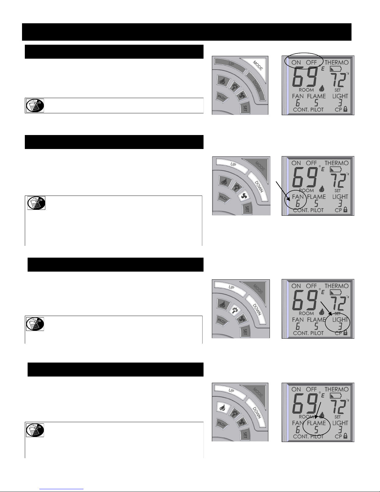
PRC-36-IPI REMOTE RECEIVER INFORMATION
MANUAL MODE:
This remote can be manually or thermostatically operated.
Press MODE button for manual ON. The flame icon will appear on the LCD
screen. Press MODE button again to put the control into THERMO mode.
Pressing MODE again will turn fireplace OFF.
NOTE: The MODE button operates in a series that will cycle from ON
to THERMO to OFF.
FAN MODE:
This remote will operate the fan, allowing for (6) different speed levels. When
the FAN button is pressed, FAN level setting will flash on the LCD screen.
Press UP or DOWN buttons to select desired fan speed level. If no adjustment is made within 7 seconds, the control will exit function setting mode and
LCD display will return to normal view.
NOTE: Delayed ON/OFF - The fan will not turn on until fireplace
has been burning for 5 minutes and will not turn off for 12
EXCEPTION: If fireplace is turned back on during 12 minute off-delay time
frame, the fan will remain on.
This applies to MANUAL and THERMO modes.
minutes after fireplace has been turned off.
LIGHTING MODE:
This remote will operate the lights, allowing for (6) different light levels.
When LIGHT button is pressed, LIGHT level setting will flash on the LCD
screen. Press UP or DOWN buttons to select desired light level. If no adjustment is made within 7 seconds, the control will exit function setting mode and
LCD display will return to normal view.
NOTE: There is a 3 second delay before light level setting is achieved.
NOTE: Light operations are completely independent from flame and fan
operations.
FLAME MODE:
This remote will operate the flame, allowing for (6) different flame height
levels. When MAIN FLAME button is pressed, FLAME level setting will
flash on the LCD screen. Press UP or DOWN buttons to select desired flame
level. If no adjustment is made within 7 seconds, the control will exit function
setting mode and LCD display will return to normal view.
NOTE: The fireplace will initially light at the highest level. After 5
seconds the flame will adjust to last chosen level before
fireplace was turned OFF.
This applies to MANUAL and THERMO modes.
PAGE 58

PRC-36-IPI REMOTE RECEIVER INFORMATION
THERMO (THERMOSTAT) MODE:
This remote feature allows you to thermostatically control the fireplace when hand held remote is set to
THERMO mode.
Set Temperature Range: 45˚F (7˚C) to 90˚F (32˚C).
Set remote to THERMO mode by pressing MODE button. The smaller SET window of numbers appears
on the LCD screen. The first SET number will read 45˚F. Press UP button to desired set room temperature. Within 5 seconds fireplace will operate to that Set Temperature. The FLAME, ON and THERMO
icons will appear on the LCD screen. By pressing UP or DOWN buttons a new set temperature may be
attained.
SET Temperature will only appear when THERMOSTAT MODE is activated,
but is implemented in all MODES with the exception of MANUAL MODE.
NOTE: The flame height can adjust up to (6) different height levels according to amount of heat
required. This range however is dictated by the Flame Level setting (see previous page).
When desired temperature is met, the fireplace will shut off until more heat is required.
To exit THERMO mode press the MODE button. This also shuts fireplace OFF.
IMPORTANT: When in THERMO mode the fireplace will not turn on until room temperature falls
below SET TEMPERATURE.
SYSTEM OPERATION WITHOUT HAND HELD REMOTE:
This system is designed to operate with the hand held remote or a thermostat, but in the unlikely event
that it is required to be operated without the hand held remote or a thermostat, follow this simple
procedure.
Slide REMOTE /OFF switch on main control module to OFF. The fireplace can now be lit and shut off
by use of the ON/OFF rocker switch.
NOTE: When operating fireplace in this capacity, the only function available is burner operation on HI.
REMOTE / OFF
PAGE 59

PRC-36-IPI LIGHTING AND SHUTDOWN
FOR YOUR SAFETY - READ BEFORE LIGHTING
WARNING: IF YOU DO NOT FOLLOW THESE INSTRUCTIONS EXACTLY, A FIRE OR EXPLOSION MAY RESULT, CAUSING
PROPERTY DAMAGE, PERSONAL INJURY OR LOSS OF LIFE.
DUE TO HIGH SURFACE TEMPERATURES, KEEP CHILDREN, CLOTHING AND FURNITURE AWAY.
This appliance needs fresh air for safe operation and must be installed so there are provisions for adequate combustion and ventilation air.
1. This fireplace is equipped with an ignition device which automatically
lights the pilot and main burner. The pilot and burner light automatically
with the hand held remote only. DO NOT try to light the pilot by hand.
Before lighting this fireplace, follow these instructions exactly.
2. BEFORE LIGHTING, smell all around the appliance for gas. Be sure to
smell next to the floor because some gas is heavier than air and will
settle on the floor.
3. Do not use this appliance if any part has been under water.
Immediately call a qualified service technician to inspect the
appliance and to replace any part of the control system which has been
under water.
DO NOT STORE OR USE GASOLINE OR OTHER
FLAMMABLE VAPORS AND LIQUIDS IN THE
VICINITY OF THIS OR ANY OTHER APPLIANCE.
WARNING: CHILDREN AND ADULTS SHOULD BE ALERTED TO THE HAZARDS OF HIGH SURFACE TEMPERATURES
AND SHOULD STAY AWAY TO AVOID BURNS OR CLOTHING IGNITION. YOUNG CHILDREN SHOULD BE
CAREFULLY SUPERVISED WHEN THEY ARE IN THE SAME ROOM AS THE APPLIANCE. CLOTHING OR
OTHER FLAMMABLE MATERIAL MUST NOT BE PLACED ON OR NEAR THE APPLIANCE.
WHAT TO DO IF YOU SMELL GAS:
Do not touch any electrical switches
Do not try to light any appliance
Do not use the phone in your building
Immediately call your gas supplier from a neighbor‟s
phone
Follow the gas supplier‟s instructions
If you cannot reach your gas supplier, call the fire department
NOTE: A PAINT SMELL WILL OCCUR DURING THE FIRST FEW HOURS OF BURNING. IT IS RECOMMENDED TO
LEAVE THE FAN OFF DURING THIS PERIOD TO HELP SPEED THE PAINT CURING PROCESS.
NOTE: THIS FIREPLACE MAY PRODUCE NOISES OF VARYING DEGREE AS IT HEATS AND COOLS DUE TO METAL
EXPANSION AND CONTRACTION. THIS IS NORMAL AND DOES NOT AFFECT THE PERFORMANCE OR
LONGEVITY OF THE FIREPLACE.
PAGE 60

PRC-36-IPI LIGHTING AND SHUTDOWN (cont.)
LIGHTING
STOP! Read safety information on previous page and front
cover of this manual before continuing.
1. Turn off all electrical power to fireplace.
ATTENTION: This fireplace is equipped with an ignition device
which automatically lights the pilot. DO NOT try to
light the pilot by hand.
2. Press hand held remote MODE button to „OFF‟.
5 MINUTES
3. Wait five (5) minutes to allow any gas that may have accumulated
inside firebox to escape. If you then smell gas, STOP! Follow
safety information on front cover and on previous page of this
installation manual. If you don‟t smell gas, go to next step.
Power OFF
OFF
4. Turn ON all electrical power to fireplace.
5. Press hand held remote MODE button to „ON‟.
CAUTION: If fireplace will not operate, follow instructions
TURNING OFF GAS TO FIREPLACE and call
your service technician or the gas supplier.
NOTE: When fireplace is initially lit, condensation will appear
on the glass; this is normal in all gas fireplaces and will
disappear after several minutes.
TURNING OFF GAS TO FIREPLACE
1. Press hand held remote MODE button to „OFF‟.
2. Turn OFF all electrical power to fireplace if service is required.
3. Turn manual shut-off valve to OFF.
Power ON
ON
Power OFF
OFF
PAGE 61

PRESSURE TESTING (PRC-36-IPI)
IMPORTANT NOTICE: Pressure check taps for manifold (outgoing) and inlet (incoming) pressure have been incorporated into the
valve. The pressure tap marked „OUT‟ measures outgoing pressure and the pressure tap marked „IN‟
measures incoming pressure. Follow instructions below for proper testing procedures.
NOTE: The appliance and its individual shutoff valve must be disconnected from the gas supply piping system during any
pressure testing of that system at pressures in excess of ½ psi.
NOTE: The appliance must be isolated from the gas supply piping system by closing its individual manual shut-off valve during
any pressure testing of the gas line at test pressures equal to or less than ½ psi (3.5 kPa).
INLET PRESSURE TEST:
1. Loosen inlet („IN‟) pressure tap screw (counter-clockwise).
2. Attach manometer using a 1/4” I.D. hose.
3. Light fireplace using hand held remote control. Note manometer reading.
4. Turn fireplace off using hand held remote control.
5. Disconnect hose and tighten screw (clockwise). Screw should be snug, do not over tighten.
9. Relight fireplace using hand held remote control. Reattach manometer to inlet pressure tap to verify that it is completely sealed.
Manometer should read no pressure.
NOTE: If inlet pressure reading is too high or too low, contact the gas company. Only a qualified gas service technician should adjust
the incoming gas pressure.
CAUTION: A LOW PRESSURE READING CAN CAUSE DELAYED IGNITION
Outlet (Manifold) Pressure Screw
Inlet Pressure Screw
PAGE 62

ERROR CODES (PRC-36-IPI only)
IGNITION SAFETY: Protection for Ignition System
Error Code: One beep every one second.
Description of Fault: Warns users if pilot is not successfully ignited in 60 seconds.
How to Clear: Press MODE button to OFF then to ON to re-attempt ignition.
What to Check:
Ensure gas supply is turned on.
Ensure orange/white leads from module are plugged into “PILOT” connection on valve body.
Verify lead from igniter on pilot assembly is connected to “I” terminal on main control module. (Clicking sound will also be heard).
Verify lead from flame sensor on pilot assembly is connected to “S” terminal on main control module. (Pilot will light but main burner will
not. Pilot will extinguish after 60 seconds and error code will alarm).
Verify black ground lead is connected to tab extending from valve bracket.
SENSOR SAFETY: Protection for Flame Sensor
Error Code: Four beeps every one second.
Description of Fault: Warns users pilot flame senor detects a pilot flame already present when ignition sequence is initiated. This fault will
also occur if pilot flame senor on main control module is shorted to ground.
How to Clear: Press MODE button to OFF then to ON to re-attempt ignition.
What to Check:
Check if pilot flame is actually present when valve is turned OFF (if yes, replace valve).
Replace pilot assembly.
Replace module.
THERMAL SAFETY: Overheat Protection
Error Code: Four beeps every two seconds.
Description of Fault: Warns users that module‟s internal temperatures have exceeded 170˚ F (77˚C).
How to Clear: Module‟s internal temperatures must cool to below 160˚F (71˚C) and then press ON button.
What to Check:
Are modules located in an unapproved location. Move to cooler location.
COMMUNICATION SAFETY: Protection for Ignition System
Error Code: One beep every four seconds.
Description of Fault: Warns users the hand held remote and main control module are not communicating properly. This safety feature is
active in both manual and thermo modes. The remote control sends a communication safety signal every 15 minutes. If
the main control module does not receive this signal, it begins a 2-hour countdown. If no communication safety signal
is received at the end of this countdown, the system will enter communication safety shutdown which turns system OFF
and emits the error code.
What to Check:
Verify batteries in hand held remote control are new.
Ensure remote control is located within 20 ft. (6 m) of main control module.
Ensure remote control is not placed directly on top of or inside a metal enclosure as this can interfere with transmission.
PAGE 63

FINALIZING THE INSTALLATION
FLAME APPEARANCE:
Flame appearance is affected by several factors including altitude, venting configuration and fuel quality. Although the venturi setting has
been factory set, adjustments may be necessary for optimal performance and visual aesthetics.
When fireplace is first lit, the flames will be blue. Flames will gradually turn yellowish-orange during first 15 minutes of operation. If
flames remain blue, or become dark orange with evidence of sooting (black tips), the burner tube venturi may need adjustment.
WARNING: BURNER TUBE ADJUSTABLE VENTURI POSITIONING SHOULD ONLY BE PERFORMED BY A
QUALIFIED PROFESSIONAL SERVICE TECHNICIAN.
FACTORY SET BURNER TUBE VENTURI SETTINGS
(ADJUST AS NECESSARY FOR YOUR INSTALLATION)
NATURAL GAS LP (PROPANE) GAS
1/8” (3 mm) OPEN 1/8” (3 mm) OPEN FRONT BURNER
BACK BURNER 5/8” (16 mm) OPEN 5/8” (16 mm) OPEN
BURNER TUBE VENTURI ADJUSTMENT GUIDELINES
VENTURI POSITION FLAME COLOR VENTURI ADJUSTMENT
Closed too far Dark orange flame with black tips Open venturi setting slightly
Open too far Blue flames Close venturi setting slightly
NOTE: IF SOOT IS PRESENT, CHECK LOG POSITIONING BEFORE ADJUSTING BURNER VENTURI. LOGS
MUST NOT BLOCK BURNER PORTS.
IMPORTANT: SLIGHT ADJUSTMENTS TO THE BURNER VENTURI OPENING CREATE DRAMATIC RESULTS.
ADJUST AT SLIGHT INCREMENTS UNTIL DESIRED LOOK IS ACHIEVED. ALWAYS BURN FIRE
PLACE FOR AT LEAST 15 MINUTES AND ALLOW TIME TO COOL BEFORE MAKING ANY FUR-
TO ADJUST BACK BURNER VENTURI:
WARNING: TO AVOID PROPERTY DAMAGE OR PERSONAL INJURY,
ALLOW FIREPLACE AMPLE TIME TO COOL BEFORE
MAKING ANY ADJUSTMENTS.
1. Remove set screw securing venturi wheel (located under firebox).
2. Moving handle towards #1 position closes venturi opening.
Moving handle towards #9 position opens venturi opening.
3. Re-install set screw.
4. Light fireplace and wait 15 minutes before determining if
any further adjustments are needed.
TO ADJUST FRONT BURNER VENTURI:
1. Follow Millivolt Board Removal instructions on page 37 to access
and remove front burner assembly.
2. Loosen screw on venturi and adjust as necessary. Tighten screw.
3. Follow Millivolt Board Installation instructions on page 38 to reinstall
all components.
PAGE 64

FINALIZING THE INSTALLATION
RESTRICTOR USAGE:
Turn fireplace on and allow to burn for 15 minutes. If flames indicate there is excessive draft (flickering, short flames) or insufficient draft
(lifting or ghosting flames) a restrictor may be necessary, or previously installed restrictor may need to be modified or removed.
WARNING: TO AVOID PROPERTY DAM AGE OR PERSONAL INJURY, ALLOW FIREPLACE AMPLE TIME TO COOL BEFORE MAKING ANY
ADJUSTMENTS AND / OR INSTALLATIONS.
RESTRICTOR TROUBLESHOOTING
FLAME APPEARANCE DRAFT PROBLEM RESTRICTOR SOLUTION
Short, flickering Excessive draft - not enough restriction Add restrictor
Lifting or ghosting* Insufficient draft - too much restriction Remove inner ring (s) on restrictor or
remove restrictor
* Improper venting installation may cause flames to lift or “ghost” - a dangerous situation. Inspect flames after installation to ensure proper performance. If it is determined that venting is correct and the restrictor has been removed, yet flames are still lifting or ghosting, shut off gas supply to fireplace and call a qualified service technician.
RESTRICTOR INSTALLATION / MODIFICATION (after termination completion):
If it is determined that a restrictor is needed or restrictor modification is required after termination is installed, access can be reached through
the fireplace baffle. Please remove logs, upper refractory clip and refractory to avoid damaging these components.
1. Remove (4) screws securing baffle. Remove baffle to expose venting.
2. Depending on your specific needs, determined by the chart above along with other factors, make necessary modifications.
3. If installation of a restrictor (included in fireplace components packet) is necessary, bend tabs on restrictor to approx. 80 degree angles to
create tension when inserted into the exhaust pipe on fireplace. Insert restrictor into 5” exhaust pipe with tabs pointing towards you.
4. If modification is necessary, remove restrictor by pulling it down and out of 5” exhaust pipe.
5. Reinstall baffle by resting baffle front above flange along inside top of firebox opening. Tip baffle back against rear firebox wall. Secure
with (4) screws previously removed.
6. Reinstall refractory panels and log set.
7. Attach glass frame assembly and light fireplace. Wait 15 minutes before determining if any further modifications are necessary.
BAFFLE
FLANGE
(4) SCREWS SECURING BAFFLE
Bend tabs to approx. 80 degree angles
to create tension to hold itself in place
LARGE
when installed.
Remove tab (s) to create small restrictor
5” EXHAUST
Slide restrictor into exhaust pipe at top of
fireplace with tabs pointing towards you.
PAGE 65

HEAT DAMPER
This fireplace has been designed to operate with the damper fully open or completely closed depending on heat output desired without compromising flame appearance.
The damper is located at the inside top of the firebox and can be viewed through the glass.
The damper control is located under the firebox.
To reduce the amount of heat entering the room, raise damper control up and push into mounting slot. The damper is now in the fully open
position and allows more heat to exit through the vent system.
If more heat is desired, pull handle out and down. The damper is now closed.
Damper
PAGE 66

MAINTENANCE
The appliance is required to be inspected at least once a year by a professional service person.
The compartment below the firebox (behind the lower grill) must be cleaned at least once a year, more frequent cleaning may be required due to
excessive lint from carpeting, bedding materials, or other fibrous materials. It is imperative that the burner be cleaned once a year.
NOTE: INSTALLATION AND REPAIR SHOULD BE DONE ONLY BY QUALIFIED SERVICE PERSON. THE APPLIANCE SHOULD BE
INSPECTED BEFORE USE AND ANNUALLY BY A QUALIFIED SERVICE PERSON. MORE FREQUENT CLEANING MAY BE
REQUIRED DUE TO EXCESSIVE LINT FROM CARPETING, BEDDING MATERIALS, ETC. IT IS IMPERATIVE THAT CONTROL
COMPARTMENTS, BURNERS AND CIRCULATION AIR PASSAGEWAYS OF THE APPLIANCE BE KEPT CLEAN .
CONTROL BOARD SYSTEM
Annual cleaning of the burner system is required.
The burner assembly may be removed for easier access. Refer to pages 37-38 in this installation manual for complete instruction on removing &
reinstalling the burner assembly.
Visually check for blocked port holes, especially near the pilot. Blocked port holes may cause delayed ignition.
Reinstall the burner assembly following instructions on page 38 of this installation manual.
Visually check pilot light and burner when in operation. The flames should be steady, not lifting or floating.
Burner Ports
PRC-36-RF Pilot PRC-36-IPI Pilot
PRC-36 Pilot
Burner Orifice
FAN
The fan should be disconnected from electrical current, and cleaned (vacuumed) every six months. The bearings are sealed and require no oiling.
VENT SYSTEM
Annual examination of the venting system by a qualified agency is required.
IF VENT-AIR INTAKE SYSTEM IS DISASSEMBLED FOR ANY REASON, RE-INSTALL PER INSTRUCTIONS PROVIDED WITH INITIAL
INSTALLATION.
The flow of combustion and ventilation air must not be obstructed.
GLASS CLEANING & REPLACEMENT
Clean glass only when cool and only with non-abrasive cleansers.
Do not operate this fireplace with the glass/frame assembly removed, cracked or broken.
The glass assembly, part #PRC-057T, shall only be replaced as a complete unit, as supplied by Hussong Mfg. Co., Inc.
Replacement of the glass & frame assembly, part #PRC-057T, must only be performed by a licensed or qualified service person.
DO NOT SUBSTITUTE MATERIALS.
Do not strike or slam glass door assembly.
IMPORTANT: ANY SAFETY SCREEN OR GUARD REMOVED FOR SERVICING MUST BE REPLACED PRIOR TO OPERATING THE APPLIANCE.
CAUTION: LABEL ALL WIRES PRIOR TO DISCONNECTION WHEN SERVICING CONTROLS. WIRING ERRORS CAN CAUSE IMPROPER AND
DANGEROUS OPERATION. VERIFY PROPER OPERATION AFTER SERVICING.
CAUTION: KEEP APPLIANCE AREA CLEAR OF COMBUSTIBLE MATERIALS, SUCH AS GASOLINE AND OTHER FLAMMABLE VAPORS AND LIQUIDS.
PAGE 67

TROUBLESHOOTING (PRC-36 only)
CAUTION: THE FOLLOWING MUST BE PERFORMED BY A QUALIFIED TECHNICIAN.
NO SPARK FROM ELECTRODE TO PILOT WHEN PIEZO BUTTON IS TRIGGERED.
A. Check wiring at back of piezo for proper connection.
B. Check wiring at electrode for proper connection.
C. Check position of electrode (1/8” (3 mm) between electrode and pilot). Readjust if necessary.
D. Look for arc below electrode and along electrode wire. Direct metal contact may cause an arc below electrode.
SPARK IGNITOR WILL NOT LIGHT AFTER REPEATED TRIGGERING OF PIEZO BUTTON.
A. No gas or low gas pressure.
♦ Check remote shut off valves from fireplace. Usually there is a valve near the main. There may be more than (1) valve between the fire
place and the main.
♦ Low gas pressure can be caused by several situations such as a bent line, too narrow diameter pipe, or low line pressure. Consult with
plumber or gas supplier.
B. No LP in tank.
♦ Check LP (propane) tank. Refill if necessary.
PILOT WILL NOT STAY LIT AFTER CAREFULLY FOLLOWING LIGHTING INSTRUCTIONS.
A. Check that pilot flame impinges on thermocouple. Clean and / or adjust pilot for maximum flame impingement.
B. Ensure the thermocouple connection at gas valve is fully inserted and tight (hand tight plus 1/4 turn).
C. Thermocouple reading below 15 millivolts.
♦ Disconnect thermocouple from valve, place one millivolt meter lead wire on end of thermocouple and other millivolt meter
lead wire on thermocouple‟s copper wire. Start pilot while holding valve knob in. If millivolt reading is less than 15 millivolts,
replace thermocouple.
.
D. Thermopile not generating sufficient millivolts.
♦ Pilot flame must be enveloping thermopile. Adjust pilot flame if necessary.
♦ Check thermopile wire connections at valve. Tighten if necessary.
♦ Check thermopile with millivolt meter. Turn remote / thermostat / wall switch or ON/OFF switch to OFF. Turn valve knob to PILOT
position (pilot should remain lit). Take reading at THTP & TP terminals on gas valve. Reading should be 350 millivolts minimum.
Replace thermopile if reading falls below specified minimum.
PAGE 68

TROUBLESHOOTING (PRC-36 only)
BURNER WILL NOT LIGHT
A. Gas control knob not turned to „ON‟.
B. „ON‟/„OFF‟ switch not turned on.
C. Remote, wall switch or thermostat not turned „ON‟.
D. Plugged main burner orifice.
E. Remote, wall switch, thermostat or „ON/ OFF‟ switch wires defective.
♦ Check wires for proper connections. Place jumper wires across terminal at switch. If burner lights, replace defective switch.
♦ If switch checks ok, place jumper wires across switch wires on gas valve. If burner lights, wires are faulty or connections are bad.
FREQUENT PILOT OUTAGES
A. Pilot shield not installed.
B. Pilot flame too high or too low, causing pilot safety to drop out.
♦ Clean and adjust flame for maximum flame impingement on thermopile.
BURNER WON‟T STAY LIT
A. Thermopile wires loose at valve terminals.
♦ Tighten if necessary.
B. Thermopile wires ground out due to pinched wires.
♦ Free pinched wires if necessary.
C Refractory panel placement (if installed).
♦ Refractory panels must be tight against firebox walls. It may be necessary to secure panels with high-temp sealant, especially around
intake duct.
PAGE 69

TROUBLESHOOTING (PRC-36 only)
PILOT AND BURNER EXTINGUISH WHILE IN OPERATION
A. No LP (propane) in tank.
♦ Check tank and refill if necessary.
B. Glass frame assembly not installed correctly.
♦ Refer to page 16 in this manual for proper glass frame assembly installment instructions.
C. Defective thermopile or thermocouple.
♦ Check thermopile and thermocouple for proper millivolts.
D. Improper pitch on horizontal vent.
♦ 1/4” (6 mm) rise per foot is required on horizontal venting.
E. Inner vent pipe leaking exhaust gases back into firebox.
♦ Check for leaks. Repair if necessary.
F. Improper vent cap installation.
♦ Check for proper vent cap installation. Maximum downward slope of horizontal vent cap is 1/4” (6 mm). Adjust if necessary.
♦ Check vent cap for blockage. Remove debris if necessary.
G. Excessive draft.
GLASS SOOTING
A. Improper log placement.
♦ Refer to log placement instructions on pages 34-36 of this installation manual.
B. Improper venturi setting.
♦ Venturi may need to be opened slightly to allow more air into gas mix.
C. Improper pitch on horizontal venting.
♦ 1/4” (6 mm) rise per foot is required on horizontal venting.
FLAME BURNS BLUE AND LIFTS OFF BURNER
A. Improper Venturi setting.
♦ Venturi may need to be closed slightly.
B. Improper vent cap installation.
♦ Check for proper vent cap installation.
C. Blockage or vent system leaks.
PAGE 70

RF REMOTE TROUBLESHOOTING (PRC-36-RF only)
If manual switch is set to
REMOTE, press Mode button
to display AUTO on the
transmitter, Does transmitter
display room and temperature
setting?
Yes
If setting is above room
temperature on transmitter,
domain valve and fan turn
on?
Yes
If setting is below room
temperature on transmitter, do
main valve and fan turn off?
Yes
Turn pilotstat knob to OFF to
turn valve completely off.
Yes
AUTO PATH
Move switch from LOCAL to
No
No
REMOTE. Press any key
within 30 seconds.
REMOTE PATH
If the manual switch is set to
REMOTE, set Mode button to
display “ON”. Does transmit-
ter control main burner and
fan ?
Yes
Does transmitter change
levels of flame height, fan
speed and set temperature?
Yes
Set levels of flame height and
fan to “0” to shut off main
burner and fan.
Turn pilotstat knob to OFF to
turn valve completely off.
Move switch from
MANUAL to RE-
MOTE. Press any key
on transmitter.
No
Set manual switch to
LOCAL or REMOTE
Yes
Light pilot burner.
Yes
Did the LED stop
blinking?
Yes
Release pilotstat
knob.
Yes
Turn pilotstat knob
from PILOT to ON.
Yes
Cycle switch once and leave
in remote. Press any key on
transmitter for recognition
operation.
Yes
Five minute wait
period.
Review LED failure
analysis.
Choose LOCAL or REMOTE
Yes
path. Set switch to LOCAL or
REMOTE.
LOCAL PATH
If manual switch is set to
LOCAL, did main burner
light?
Yes
Does transmitter control fan.
Yes
Turn pilotstat knob to PILOT
to turn off main burner.
Turn pilotstat knob to OFF to
turn valve completely off.
Move switch from
LOCAL to REMOTE.
Press any key on trans-
mitter. Move switch
back to LOCAL.
No
PAGE 71

TROUBLESHOOTING (PRC-36-RF only)
CAUTION: THE FOLLOWING MUST BE PERFORMED BY A QUALIFIED TECHNICIAN
NO SPARK FROM ELECTRODE TO PILOT WHEN PIEZO BUTTON IS TRIGGERED.
A. Check piezo wiring for proper connection.
B. Check position of electrode (1/8” (3 mm) between electrode and pilot). Readjust if necessary.
C. Look for arc below electrode and along electrode wire. Direct metal contact may cause an arc below electrode.
SPARK IGNITOR WILL NOT LIGHT AFTER REPEATED TRIGGERING OF PIEZO BUTTON.
A. No gas or low gas pressure.
♦ Check remote shut off valves from fireplace. Usually there is a valve near the main. There may be more than (1) valve between
fireplace and main.
♦ Low gas pressure can be caused by several situations such as a bent line, too narrow diameter pipe, or low line pressure. Consult with
plumber or gas supplier.
B. No LP in tank.
♦ Check LP (propane) tank. Refill if necessary.
PILOT WILL NOT STAY LIT AFTER CAREFULLY FOLLOWING LIGHTING INSTRUCTIONS.
A. Check that pilot flame impinges on thermopiles. Clean and / or adjust pilot for maximum flame impingement.
B. Ensure thermopile connections at gas valve are properly connected. The negative leads (white) must be connected
to terminals with the one white dot next to them.
BURNER WILL NOT LIGHT
A. Gas control knob not turned to „ON‟.
B. Plugged main burner orifice.
FREQUENT PILOT OUTAGES
A. Pilot shield not installed.
B. Pilot flame too high or too low, causing pilot safety to drop out.
♦ Clean and adjust flame for maximum flame impingement on thermopiles.
FLAME BURNS BLUE AND LIFTS OFF BURNER
A. Improper Venturi setting.
♦ Venturi may need to be closed slightly.
B. Improper vent cap installation.
♦ Check for proper vent cap installation.
C. Blockage or vent system leaks.
PAGE 72

TROUBLESHOOTING (PRC-36-RF only)
BURNER WON‟T STAY LIT
A. Thermopile wires loose at valve terminals.
♦ Adjust if necessary.
B. Thermopile wires ground out due to pinched wires.
♦ Free pinched wires if necessary.
C Refractory panel placement (if installed).
♦ Refractory panels must be tight against firebox walls. It may be necessary to secure panels with high-temp sealant, especially around
intake duct.
PILOT AND BURNER EXTINGUISH WHILE IN OPERATION
A. No LP (propane) in tank.
♦ Check tank and refill if necessary.
B. Glass frame assembly not installed correctly.
♦ Refer to page 16 in this manual for proper glass frame assembly installment instructions.
C. Improper pitch on horizontal vent.
♦ 1/4” (6 mm) rise per foot is required on horizontal venting.
D. Inner vent pipe leaking exhaust gases back into firebox.
♦ Check for leaks. Repair if necessary.
E. Improper vent cap installation.
♦ Check for proper vent cap installation. Maximum downward slope of horizontal vent cap is 1/4” (6 mm). Adjust if necessary.
♦ Check vent cap for blockage. Remove debris if necessary.
F. Excessive draft.
GLASS SOOTING
A. Improper log placement.
♦ Refer to log placement instructions on pages 34-36 of this installation manual.
B. Improper venturi setting.
♦ Venturi may need to be opened slightly to allow more air into the gas mix.
C. Improper pitch on horizontal venting.
♦ 1/4” (6 mm) rise per foot is required on horizontal venting.
PAGE 73

TROUBLESHOOTING (PRC-36-IPI only)
MAIN CONTROL MODULE WILL NOT LEARN TRANSMITTER
Ensure REMOTE/OFF switch on side of main control module is set to REMOTE.
Make sure batteries in both the hand held remote and backup battery pack are installed in the proper direction and are not drained.
Verify hand held remote indicates a signal is being sent. The LCD display should indicate ON or OFF depending on which button is being pressed. The LED indicator should illuminate on wall transmitters and on/off transmitters. Buttons should be pressed and held for 1 to
2 seconds to ensure a complete signal is sent.
Ensure 4-pin lead-set is securely connected from battery pack to main control module‟s AUX connection. If the A/C adapter is used,
check that leads from adapter are securely connected to POWER terminals on main control module.
Press and hold LEARN button on main control module for approximately 10 seconds to clear memory (you should hear a series of beeps
from the receiver), immediately press either the ON or OFF button on hand held remote (you should hear a series of beeps indicating the
transmitter code has been learned).
PILOT WILL NOT LIGHT / STAY LIT
Verify gas supply is turned on.
Verify main control module is receiving signal from hand held remote by listening for a beep from receiver when ON is pressed on hand
held remote. If you do not hear a beep, ensure main control module has learned the hand held remote. (See above).
Ensure black lead from pilot assembly igniter is securely connected to terminal labeled “I” and red lead from flame rectification sensor is
securely connected terminal labeled “S” on main control module.
Make sure orange and white leads from main control module are securely connected to terminals labeled “PILOT” on valve body.
Ensure black GROUND wire is securely connected to tab located next to ON/OFF toggle switch. A proper ground is essential to spark
igniter operation.
Make sure pilot flame is in contact with flame rectification sensor on pilot assembly. This valve is equipped with a pilot flame adjustment
screw. If pilot flame is too small it will not contact flame rectification sensor and will not complete the safety circuit.
Check continuity of pilot on valve. Remove wire connector. If there is no continuity on pin terminals, replace valve.
PILOT FLAME ALWAYS ON / WILL NOT EXTINGUISH
Ensure continuous pilot icon is not present in LCD screen. If icon is present, press PILOT button. This will de-activate the continuous
pilot feature and the icon will disappear from LCD screen.
PILOT BURNING BUT IGNITER CONTINUES TO SPARK
Check that flame sensor is fully impinged by pilot flame. If needed, adjust pilot.
Check end-to-end continuity of sensor. If sensor has continuity, replace module.
PAGE 74

TROUBLESHOOTING (PRC-36-IPI only cont.)
MAIN FLAME WILL NOT LIGHT
Verify gas supply is turned on.
Ensure pilot flame will ignite. If not, see pilot flame troubleshooting on previous page.
Make sure green and white leads from module are securely connected to terminals marked “MAIN” on valve body.
Make certain pilot flame is in contact with flame rectification sensor on pilot assembly. This valve is equipped with a pilot flame adjustment screw. If pilot flame is too small it will not contact flame rectification sensor and will not complete the safety circuit.
Ensure pilot flame is properly located to ignite main flame.
Does hand held remote show CP in the display? If yes, childproof is on. De-activate by pushing PROG/TIME & UP keys at same time
for more than 5 seconds.
Check continuity of main burner coil on gas valve. Remove wire connector. If there is no continuity on pin terminals, replace valve.
FLAME HEIGHT ADJUSTMENT NOT WORKING / WORKS BACKWARDS
Ensure black and red leads from battery pack module are securely connected to red and black leads from motor drive located on valve body
(red to red, black to black).
Check functionality with all transmitters to determine if there is an issue with the main control system or an individual transmitter. If the
issue is with an individual transmitter, make sure batteries in hand held remote and backup battery pack are installed properly and are not
drained.
ROOM TEMP. DISPLAYED ON HANDHELD REMOTE NOT CORRECT.
Ensure transmitter was not recently stored in a different location (air-conditioned, heated) from that in which the hand held remote was
tested. It may take up to 3 hours for the temperature inside a packaged transmitter, and several minutes for an unpackaged transmitter to
equalize with room temperature.
FIREPLACE WILL NOT RESPOND IN “THERMO” MODE
Ensure hand held remote is within 20 ft. (6.096 m) operational range.
Make sure an ON or OFF command was not last sent from another transmitter. These commands will override thermal commands from the
handheld remote control. To return system to THERMO mode, press either ON or OFF on hand held remote, then press MODE button to
put system in THERMO mode. Press and hold SET button to change set temperature.
Verify set temperature on hand held remote is at least 2˚F (1˚C) above or below room temperature. The system will not react to temperatures within 2˚F (1˚C) of set temperature.
PAGE 75

REPLACEMENT PARTS LIST
Replacement parts are available through your local dealer. Contact them for availability and pricing.
PRC-36 MILLIVOLT BOARD AND PARTS
PRC-770 Millivolt Board - Nat Gas 700-098 Pilot Hood
PRC-771 Millivolt Board - LP Gas 700-203 Manual Shut-off Valve
700-023 On/Off Rocker Switch 700-213 18” Flexible Gas Line-Black
700-086N S.I.T. Valve - Natural Gas 700-226 Flexible Gas Line-Valve to Burner Connection
700-087 S.I.T. Valve - LP Gas 700-255 Natural Gas Orifice #55- front burner
700-088 Pilot / Generator / Thermocouple - Nat Gas 700-237 NAT Gas Orifice #37 - back burner
700-089 Pilot / Generator / Thermocouple - LP Gas 700-271 LP Gas Orifice #71 - front burner
700-090 Piezo Igniter w/ Nut (no wire) 700-252 LP Gas Orifice #52 - back burner
700-099 Flexible Pilot Tubing (Valve to Pilot) OCK-S3755 Natural Gas Conversion Kit
700-092 Millivolt Generator OCK-S5271 LP Gas Conversion Kit
700-093 Thermocouple PRC-135 Burner / Log Grate Assembly
700-094 #51 Pilot Orifice - Natural Gas PRC-043 Pilot Shield
700-095 #30 Pilot Orifice - LP Gas
PRC-36-RF MILLIVOLT BOARD AND PARTS
PRC-800RF RF Millivolt Board - Natural Gas 700-213 18” Flexible Gas Line-Black
700-107 Honeywell RF Valve - Natural Gas 700-226 Flexible Gas Line-Valve to Burner Connection
700-108 Remote Control - RF Valve 700-255 Natural Gas Orifice #55- front burner
700-109 Honeywell RF Pilot Assembly 700-237 NAT Gas Orifice #37 - back burner
700-060 Flexible Pilot Tubing (Valve to Pilot) 700-271 LP Gas Orifice #71 - front burner
700-092 Millivolt Generator 700-252 LP Gas Orifice #52 - back burner
700-203 Manual Shut-off Valve OCK-H3755N-RF Natural Gas Conversion Kit
700-213 18” Flexible Gas Line - Black OCK-H5271L-RF LP Gas Conversion Kit
700-213 6” Flexible Gas Line-Valve to Burner Connection PRC-135 Burner / Log Grate Assembly
700-098 Pilot Hood PRC-043 Pilot Shield
700-203 Manual Shut-off Valve
PRC-600-IPI PRC-36-IPI Board - Nat Gas 700-203 Manual Shut-off Valve
PRC-601-IPI PRC-36-IPI Board - LP Gas 700-213 18” Flexible Gas Line-Black
700-400 Main Control Module 700-226 Flexible Gas Line-Valve to Burner Connection
700-404 IPI Valve - Natural / LP Gas 700-255 Natural Gas Orifice #55 - front burner
700-199 Pilot Assembly - Natural Gas 700-237 NAT Gas Orifice #37 - back burner
700-199-1 Pilot Assembly - LP Gas 700-271 LP Gas Orifice #71 - front burner
700-800 8-PIN Primary Wire Harness: Primary Wire Harness 700-252 LP Gas Orifice #52 - back burner
700-500 5-PIN Wire Harness: Main Module to Valve Step Motor OCK-A3755N-IPI Natural Gas Conversion Kit
700-120 Extension Module OCK-A5271L-IPI LP Gas Conversion Kit
700-401 4-PIN Wire Harness: Control Module to Extension Module PRC-135 Burner / Log Grate Assembly
700-750 7.5 Volt Adaptor PRC-043 Pilot Shield
700-208 IPI Remote Control AF-LLS-99 #99 Low Limit Screw
700-166 #62 IPI NAT. Gas Pilot Orifice 700-752 Pilot Igniter (with wire)
700-168 #35 IPI LP Gas Pilot Orifice 700-753 Pilot Flame Sensor (with wire)
700-751 Battery Back-up with (4) AA Batteries
PRC-36-IPI BOARD SYSTEM AND PARTS
PAGE 76

REPLACEMENT PARTS LIST (cont.)
GLASS & GLASS GASKET
PRC-005 Replacement Valance
900-006 1-1/8” Glass Gasket w/ Adhesive
PRC-057T Valance with 24-3/4” x 30-1/2” glass
REFRACTORY PANELS
(Sandstone)
PRC-G900 (3 pc.) Refractory Panel Set
PRC-G900S Side Refractory (1 pc.)
PRC-901E Ember / Log Refractory
PRC-G902 Top Refractory Panel
PRC-G900B Back Refractory Panel
GRILL REPLACEMENT
PRC-200 Upper Hood
PRC-201 Lower Grill
PRC-200L Upper Hood Louver
LOG SET
PRC-500 Log Set
PRC-1 #1 Log
PRC-2 #2 Log
PRC-3 #3 Log
PRC-4 #4 Log
PRC-5 #5 Log
PRC-6 #6 Log
PRC-7 #7 Log
PRC-8 #8 Log
PRC-9 #9 Log
900-KLK Klinkers
900-REMB Rock Wool Embers
LIGHT KIT (55345-IPI only)
600-676 35 Watt 120V Halogen Bulb
600-678 Amber Colored Light Filter
FAN ASSEMBLIES
RF-028 Fan Assembly (RF & ST units only)
TRF-028 Fan Assembly (PRC-36 only)
IPI-028 Fan Assembly (PRC-36-IPI only)
*Consult your dealer for information on optional accessories available for this fireplace.
This appliance tested & certified by:
OMNI - Test Laboratories, Inc.
13327 NE Airport Way
Portland, Oregon 97230
Model #PRC-36 Princeton
Model #PRC-36-RF Princeton RF
Model #PRC-36-IPI Princeton IPI
October 2009-REV-08
Manufactured by:
Hussong Mfg. Co., Inc.
204 Industrial Park Drive
Lakefield, Minnesota 56150
507-662-6641
www.kozyheat.com
PAGE 77

PAGE 78

PAGE 79
 Loading...