

Kozlusan Propel 40, Propel 25 Owner's Manual
Green Energy Engineering Ltd, 198 Lurgan Road, Dromore, Craigavon, Co.Down, Northern Ireland. BT25 1HL
Tel: +44 (0) 28 38 820 043 Fax: +44 (0) 28 38 820 987 Email: info@geeltd.org
MODEL: PROPEL
BE SURE TO READ THIS MANUAL AND KEEP IT NEAR THE HEATING SYSTEM
FOR EASY REFERENCE

2 | P a g e
TABLE OF CONTENTS
Section Page
Introduction 3
Safety instructions 4
How to biomass system Works 6
Specifications 8
Installation 11
Operating the Heating system 14
Maintenance Overview 15
Troubleshooting 18
Installation Scheme 20
Electrical Scheme 22

3 | P a g e
INTRODUCTION
Congratulations on your purchase of a biomassfired heating system from KOZLUSAN HEATING
SYSTEMS.
With proper installation and maintenance, your heating system will provide years of non-polluting,
low cost heat for your home.
To insure correct installation and safe operation of your Kozlusan biomass heating system, you
should:
Hire a licensed heating contractor to install the biomass heating system and integrate it with
your heating system. This contractor should have experience with installation and operation of gas, oil,
and solid fuel heating appliances and be familiar with local building codes, fire codes and other
regulations.
Read this manual and learn how to safely operate and maintain your Kolzusan biomass heating
system.
The assembling and start up (setting) of Kozlusan biomass boiler has to be carried out by
our own customer service or by authorized qualified technicians.
Do not use any other fuels than specified below:
Ö-Norm M 7135
DIN-PLUS Norm
SWISSPELLET
Diameter: 6 mm Length: 5-30 mm (20% - 45 mm)
DD: CEN / TS 14961 : 2005
Only this way low-emission, economical and reliable operation can be guaranteed. Any disregard of
these requisites leads to immediate expiry of warranty.
The pellets must be stored in dry conditions to enable them to be transported without problems
and to achieve trouble-free operation with optimum combustion combined with the greatest possible
efficiency.
We do not assume any liability for unauthorized technical modifications, and resulting damages
are not covered by warranty.
Operational procedures or alterations of any sort, carried out by unauthorized persons, as well as
disregarding the general guidelines and the indicated safety instructions as specified here, result in
immediate termination of all warranty claims.
Please read the safety instructions below before operating the system. Disregarding the safety
instructions may lead to injuries, perilous situations or damage the pellet boiler.

4 | P a g e
SAFETY INSTRUCTIONS
The pellet heater system may only be operated be in faultless technical condition. Malfunctions
and damage which affect or could affect safety must be corrected immediately by our trained
personnel.
The assembly may only be conducted by our customer service, or by a certified specialist. The
system is equipped with rotating parts, which move with a relatively large turning movement
(crushing hazard).
Under the casing and in the terminal box there are voltaged components. Do not remove the casing
or terminal box.
Never open the inspection openings of the boiler while in continuous operation, hot exhaust gas
and dust may escape.
The system should be turned off before the implementation of maintenance work. Wait until the
pellet boiler has cooled down (check the temperature on the display).
The boiler needs to be switched off before carrying out the cleaning of the chimney. Wait until the
pellets have burned down completely (approx. 20 minutes – danger of explosion through back up of
exhaust gas.
Never pour flammable liquids into the burner.
Never perform independent repair work on our system, call trained personnel!
Put a signboard into the heating room that forbids to smoke or to use open light or fire.
A certified fire extinguisher must be installed in the boiler room.
Ensure enough air supply in the heating room.
Secure the boiler room against unauthorized access, especially by children.
Once a month, test the boiler doors and the water connections for leaks and damage.
Once a year, test the safety temperature limiter.
Safety and monitoring devices may not be removed, bypassed or taken out of service in any other
way.

5 | P a g e
Always wear a dust mask when cleaning the system and when removing ashes to avoid damages to
your health.
When setting the domestic water temperature above 60 °C, you have to ensure that the hot water is
mixed with cold water to avoid scald.
The pellet heater system may only be set up and operated in heating and plant rooms which
comply with legal requirements.
Provide an appropriate air relief valve on top of the boiler.
Annual control of safety devices by a specialist.
Regular control of expansion tank by a specialist.
Regular control of pellet feeding devices, automatic ignition devices and feeding features.
Please note that even when the system is turned off, different functions are in operation. (For
example the anti-freeze protective device; pumps and mixers are moved periodically during the night
avoid an accumulation of the storings). To ensure that no electricity runs through the system, take
off the system from electricity.
Make sure that the return temperature does not drop below 50 °C. Disregarding leads to expiry of
warranty!
6 | P a g e
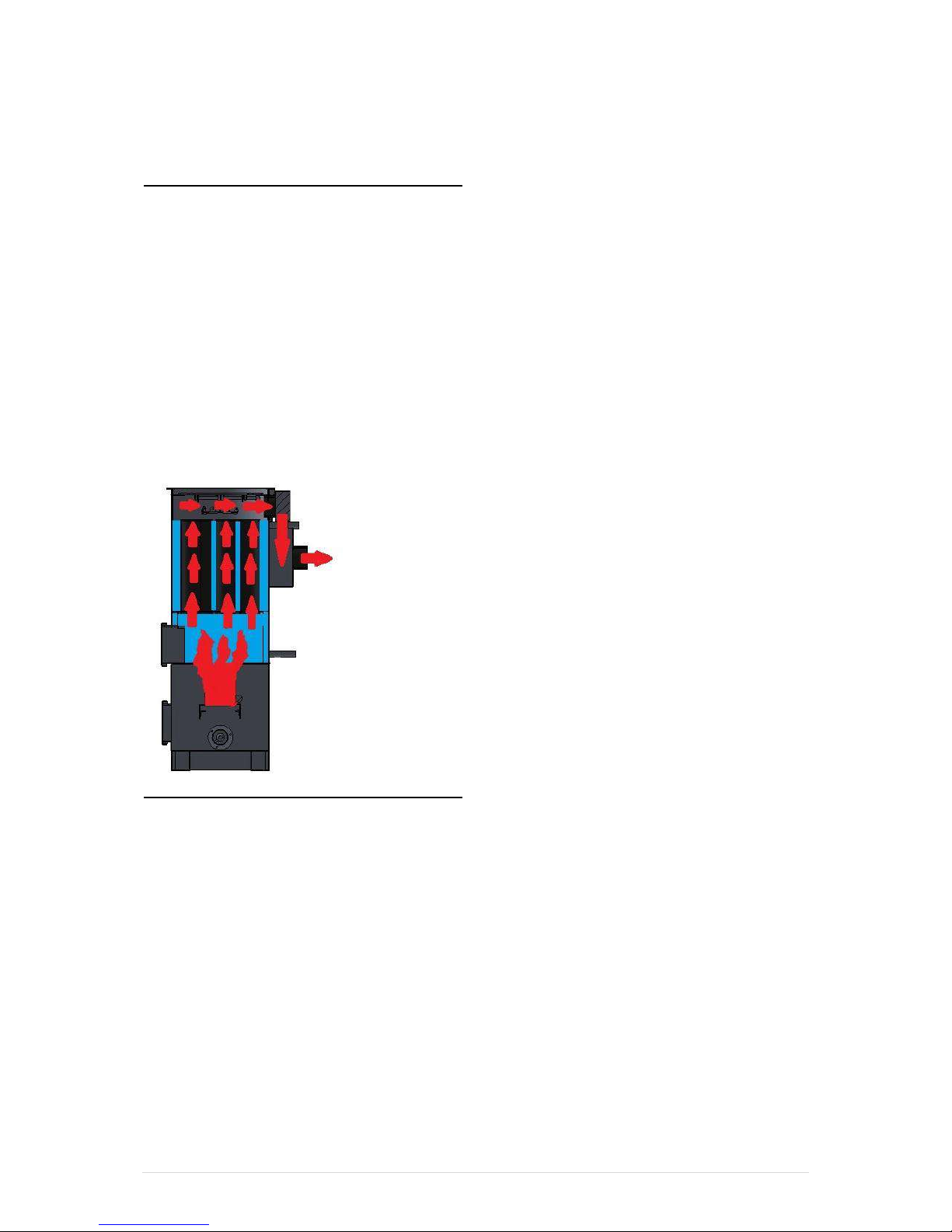
How the biomass heating system works
The Kozlusan biomass heating system produces few emissions and achieves a high level of heating
efficiency because of its unique design. The fully automated fuel delivery is „poured from top‟ into
an air fed burn pot where the fuel is self ignited before the full modulation control system controls
the burn for minimum emissions with maximum heat output.
To understand how the Kozlusan heating system works, have a to look at the flow of air, fuel
and gases through the heating system and the transfer of heat from the superheated gases to
the thermal transfer fluid. We also need to understand some of the terminology used to
describe the systems operation;
Air Flow through the Biomass heating system
1. Fuel is fed from the fuel store via an auger. The fuel is poured from the top into the cylindrical burn
pot to maintain a physical separation between the fuel store and the fuel feed. There is sucktion fan
availabe for the combustion. Various sensors measure temperature in the boiler (a thermostat that
works in water) a flue gas temperature sensor (probe in the chimney), outside temperature sensor (the
weather or room temperature) and a safety cut off temperature sensor to protect against overheating
(high limit stat).
2. As air flows through the firebox, its temperature rises to nearly 1000º C.
3. This superheated air rises upwards and then through a series of heat tubes where the heat is
transferred into the thermal fluid.

7 | P a g e
4. By the time the exhaust air reaches the flue, most of its thermal energy has been absorbed. The final
temperature of the escaping flue gas is less than 175° C.
Fluid Flow through the Heating system
1. Kozlusan heating systems recommends a mixture of water and propylene glycol as a heat transfer
fluid. Glycol is a non-toxic solution that works like the antifreeze in your car to prevent corrosion and
freezing.
2. A pump pushes fluid around the heat transfer jacket which absorbs heat from the combustion gases.
The fluid exits the internal manifold at about 80-85º C.
3. The fluid flows past an aquastat (water thermostat) that regulates the burn rate of the heating system
in conjunction with the flue gas temperature sensor that measure the temperature in the flue. This
information is used to determine the amount of air and fuel being used to ensure efficient heat transfer
and to ensure the fan does not simply blow the heat up the flue. The heated fluid is used to transfers
the heated fluid to your home system where it provides warmth to your home, garage, basement and
other structures; preheats your domestic hot water; heats your pool; and/or melts snow on your
driveway.
4. Having transferred the heat to the home system, the fluid exits the external heat exchanger and
repeats its path through the internal manifold.
8 | P a g e
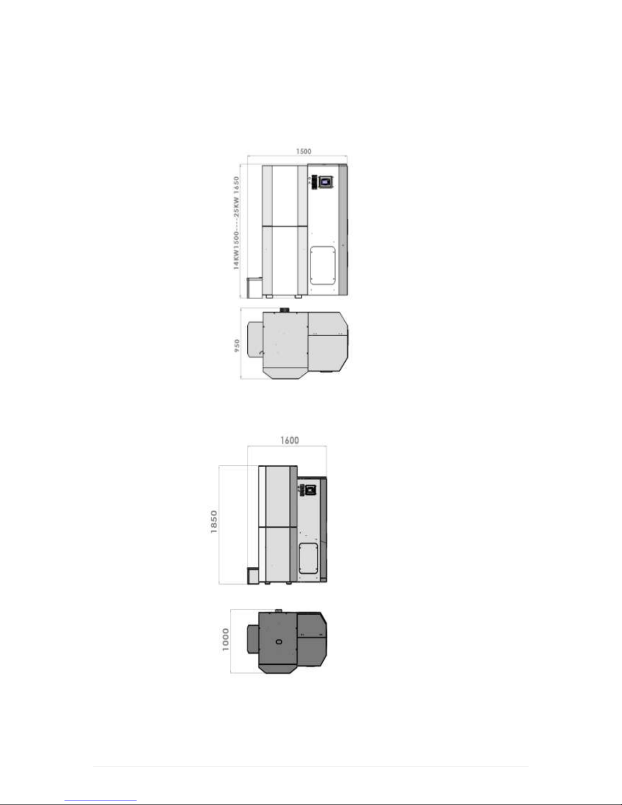
SPECIFICATIONS
Propel-25
Propel 40
 Loading...