

Kozi Previa Owner's Manual
KOZI Previa Free
Standing Pellet Stove
ARNING
W
HOT
SURFACES! Glass and
other surfaces are hot during
operation and cool down.
Hot gla
ss will cause burns.
• Do not touch glass
• NEVER allow children to touch glass.
• Keep children away.
• CAREFULLY SUPERVISE children in
same room as fi replace.
• Alert children and adults to hazards of high
temperatures.
• High temperatures may ignite clothing or
other fl ammable materials.
• Keep clothing, furniture, draperies and
other fl ammable materials away.
until it is cooled.
OWNER’S MANUAL
MX2TM CONTROL EQUIPPED
WOOD PELLET BURNING HEATER
* INSTALLATION * OPERATION *
SERVICE * PARTS *
U.S. EN
PROTECTION AGENCY
Certifi ed to comply with
2020 particulate emission
standards using pellet fuel.
Manufactured By:
APR Industries Ltd.
1354 Waverley Street
Winnipeg, MB
Canada, R3T 0P5
Ph: (204) 452-9907
Fx: (204) 453-2747
Em: mail@kozistoves.com
VIRONMENTAL
CAUTI
ON:
Read all instructions carefully before starting the
installation or operating the heater. Failure to follow these
instructions could result in property damage, bodily injury
or even death. Contact local building or fi re offi cials about
restrictions and installation inspection requirements in
your area. Save this manual for future reference.
Printed in Canada
Revised July 2015
WWW.KOZISTOVES.COM
Page 1

If you
have any questions, comments or concerns regarding
your new KOZI pellet stove, please contact your local dealer
or APR Industries Ltd by phone at (204) 452-9907 or by
visiting our website at WWW. KOZISTOVES.COM.
CAUTION: Stove has moving parts. Disconnect power
before servicing.
Please contact your local building offi cials (i.e. municipal,
building department, fi re department, fi re prevention bureau,
etc.) to determine the need to obtain a permit.
This wo
od heater needs periodic inspection and repair for
proper operation. It is against federal regulations to operate
this wood heater in a manner inconsistent with operating
instructions in this manual.
The sto
ves have been found to be in compliance with the
following standards:
ULC S628 (1993), ASTM E1509 (2004), ULC S627 (2000),
UL 1482 (2011), ULC/ORD C1482 (1990), ASTM E2779
(2010), and ASTM E2515 (2011).
Page 2

TAB
LE OF CONTENTS
I. SAF
ETY FIRST!!! 5
II. STOVE SPECIFICATIONS 7
III. INSTALLATION 7
1. Clearance to Combustibles 7
i. Installation Clearances 7
ii. Other Clearances and Recommendations 9
2. Electrical Requirements 10
3. Fuel Requirements 11
i. Physical Properties 11
ii. Fuel Storage 11
4. Location of the Heater 12
5. Typical Installation Confi gurations 13
6. Venting System 14
i. Exhaust Vent Pipe Requirements 14
ii. Exhaust Vent Pipe Requirements 15
iii. Combustion Air Intake Requirements 16
7. Mobile Home Additional Installation Requirements 17
i. Typical Mobile Home Installation Confi guration 17
ii. Recommendations for Mobile Home Installation 18
iii. Mobile Home Combustion Air Intake Requirements 18
iv. Exhaust Vent Requirements 19
v. Other Mobile Home Installation Requirements 19
IV. OPERATION 19
1. General Overview 19
2. Safety Features 20
3. Electric Igniter 21
TM
4. MX2
Control
s 21
i. Basic Description 21
ii. “AUTO, HIGH/LOW, MANUAL” Modes 21
iii. “ON/OFF” Button 22
iv. “HEAT SELECT” Button & Bar Graph 22
v. “AUGER” Button 22
vi. “FAN” Button 23
vii. “TRIM” Button 23
viii. Wall Thermostat, Wall Switch or Other Switching
Device 23
ix. Damper Control 24
x. Starting Your Heater for the First Time 25
Page 3

xi. Starting/Lighting your Heater 25
xii. Stopping Your Heater 26
xiii. Adjusting Your Heater 27
V. MAINTENANCE & CLEANING 27
VI. TROUBLESHOOTING GUIDE 33
1. Troubleshooting 33
2. Corrective Actions 34
i. Proof of Flame Failure 34
ii. Pressure Switch Failure 34
iii. Manual Reset Thermal Disk Failure 35
iv. Ignition Failure 35
v. Overheating 35
vi. Lack of Air 36
VII. DIAGRAMS AND PARTS LIST 37
TM
1. KOZI MX2
Control
Circuit Diagram 37
2. Stove Cross Section 38
3. Equipment Compartment 39
4. Parts List 41
VIII. WARRANTY 42
1. Warranty Registration Card 43
Page 4

I.
SAFETY FIRST!!!
This heater is suitable for both mobile home and conventional home installation.
Read all instructions carefully before starting installation. Save this manual for
future reference.
1. Read these instructions carefully. Failure to follow them could
cause a malfunction of the heater, damage to the heater, property
damage, bodily injury or even death.
2. Familiarize yourself with the heater’s operation (see “Operation”
section). If you are not sure, ask your dealer for explanations on
your heater’s proper operation.
3. The burn pot of this heater is designed to burn premium grade
wood pellets. Pellets with too much fi nes and saw dust must be
screened before use. DO NOT USE WET PELLETS. Refer to
the “Fuel Requirements” section for more information.
4. Oil the circulation fan motor bearings every 6 months. See
“Maintenance” section for more details.
5. Check your local building codes regarding restrictions or
installation requirements. All installations must comply with
local building codes.
6. This heater requires a fl oor protector beneath the heater and
extending a minimum of 6 inches (150 mm) in front and beyond
each side of the fuel loading and ash removal openings of the
heater. This is to catch any spillage which may occur during
opening and closing of the doors. See Figure 1 for more
information.
7. Use only UL/ULC listed Type PL or Type L venting for the
exhaust system. This heater is designed for use with 3 inch (76
mm) diameter vent pipe. Avoid long runs and too many bends.
It may be necessary to increase the size of the vent pipe to 4
inch (102 mm) in diameter if long runs and too many bends are
unavoidable. See “Venting System” section for more information.
8. Combustion of wood pellet fuel leaves ash in the heater and
venting system. These ashes must be removed from the heater
and venting on a regular basis (approximately once a week or
more frequently for high ash content fuels). See “Maintenance”
section for more information. The entire system must also be
cleaned at the start of each heating season. A yearly inspection of
the venting is highly recommended.
9. The heater must be turned off and allowed to cool before cleaning.
Make sure there are no hot ashes or embers present. Use a brush
and scoop to clean. Only use vacuum cleaners specifi cally
designed for use with hot ashes. Place all ashes in a sealed metal
Page 5

contai
ner with a tight, nonfl ammable fi tting lid.
10. Store all pellet fuel in a sealed metal container at a safe distance
(at least 36 inches/ 1 meter) away from the heater. DO NOT
place the fuel within the installation clearances of the stove or
within the space needed for ash removal and start up.
11. This heater is POWER VENTED (the vent pipes have a positive
pressure during operation). It is IMPERATIVE that all joints
in the venting system be SEALED to prevent any leakage of
exhaust gases inside the house. All joints must be sealed using
high temperature (RTV) silicone sealer. Aluminum tape is not an
adequate sealant.
12. Use of outside combustion air is highly recommended and
is mandatory in mobile home installations. Connect the air
intake pipe of the heater to the exterior of the building with a
noncombustible metal pipe with a minimum diameter of 2 inches
(50 mm). Use APR Part Number AK 100. Use of plastic pipe is
not permitted.
13. This appliance is wired and grounded according to the CSA
C22.1 code for Canada and the NFPA 70 code for the USA. Also,
this heater meets the fuel burning appliance installation codes
NFPA 211 in the USA and CSA B365 in Canada.
14. Do NOT operate the heater with the door open. Make sure the
door and any other opening in the stove are closed tightly during
operation. Inspect the gaskets of the door and other openings
periodically to make sure they are in good condition.
15. Replace broken or defective components only
with parts provided by the manufacturer. Visit
WWW.KOZISTOVES.COM or contact your local dealer to fi nd
out how to purchase replacement parts.
16. Follow this manual carefully for proper installation. If you
are uncertain, call your dealer. Most dealers have qualifi ed and
trained installers. We highly recommend the use of their services.
17. Your KOZI stove should be installed, operated and maintained
regularly in accordance with this manual. Failure to follow this
manual may cause smoke spillage or other potential hazards.
Install a smoke and carbon monoxide detector on every fl oor of
your home. Install these detectors near sleeping areas and near
the stove. Follow all manufacturers’ instructions when operating
the smoke and carbon monoxide detectors. Maintain these
detectors as stated by the manufacturer.
Page 6
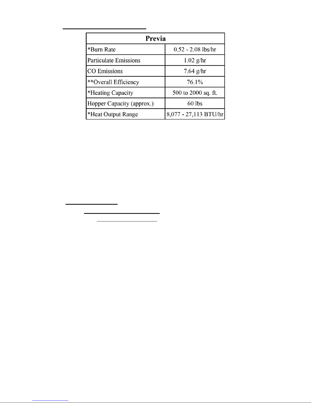
II
. STOVE SPECIFICATIONS
* V
alues will vary depending on the quality of pellet fuel being used.
** The Higher Heating Value (HHV) is used to determine the effi ciency in
accordance with CSA B415.1-09. The HHV is the total amount of heat in a
sample of fuel (including the energy in the water vapor that is created during the
combustion process). The Lower Heating Value (LHV) is the amount of heat
in a sample of fuel minus the energy in the combustion water vapor. Using the
HHV will give us a more accurate effi ciency rating.
III. INSTALLATION
1. Clearance to Combustibles
i. Installation Clearances
Please refer to the following fi gures for all clearances to combustibles. Please
note that these clearances are for your KOZI heater only. Each venting
manufacturer/supplier has their individual clearances which must also be
respected.
Figure 1
. KOZI Cast Iron Stove noncombustible fl oor protector.
Page 7
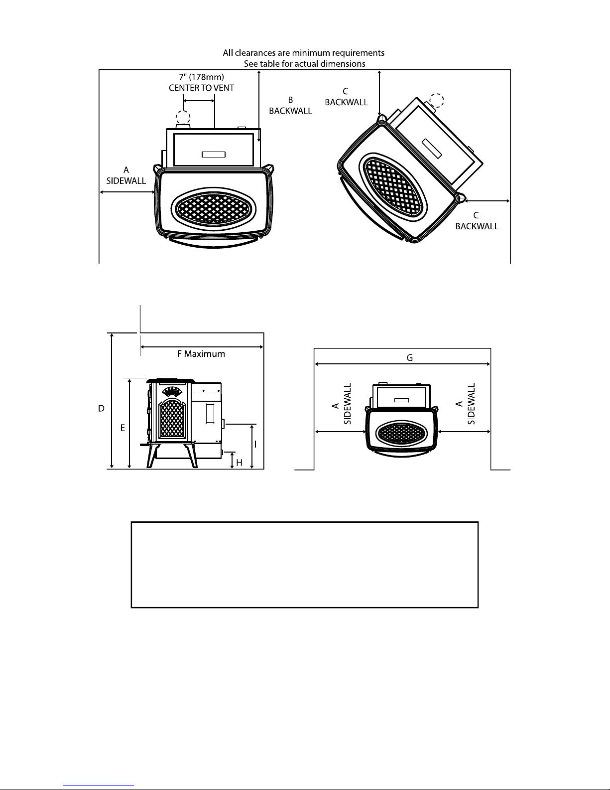
Figure 2
. Sidewall clearances
Figure 3. Alcove clearances.
ALLATION COMMENT: We recommend suffi cient
INST
space be provided (minimum 20 inches/500 mm) on each
side of the heater to service the equipment area. If this is not
possible, a provision must be made to pull the heater out for
service.
Page 8
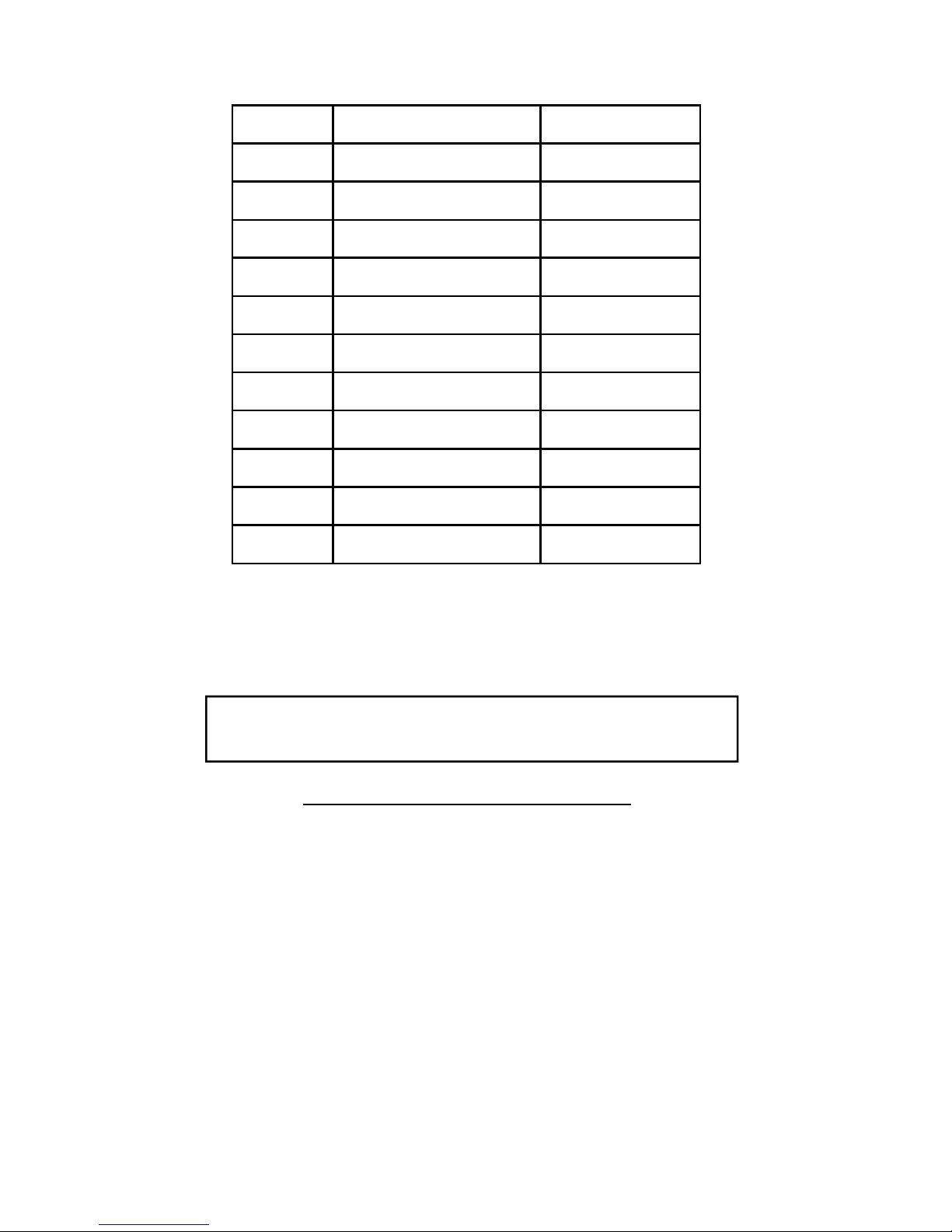
All dimensions are minimum dimensions unless marked.
Dimension Description Previa
A
B
C
D
E
F
G
H
K
Unit to side wall or side facing
Unit to back wall
Corner of unit to wall
Alcove height
Overall unit height
Alcove depth (Maximum)
Alcove width
Floor to centerline air intake
I
J
Floor to centerline exhaust
Unit to mantle
Unit to top facing
able 1. Clearance Dimensions
T
5" (125 mm)
1 " (25 mm)
1 " (25 mm)
48 " (1220 mm)
30 " (760 mm)
30 " (760 mm)
34" (865 mm)
5.125 " (130 mm)
14.5" (370 mm)
N/A
N/A
Additional installation information can be found in the “Typical Installation
Confi gurations” section and your venting manufacturer’s/supplier’s literature.
INSTALL VENT AT CLEARANCES SPECIFIED BY THE
VENT MANUFACTURER
ii. Other C
learances and Recommendations
1. This heater must be mounted on a noncombustible material,
placed underneath the heater and extending a minimum of 6
inches (150 mm) in front and beyond each side of the fuel loading
and ash removal openings of the heater.
2. Clearances can ONLY be reduced by means approved by local
building fi re offi cials in your area.
3. A safety certifi cation label has been attached to the back of the
heater. A sample label is shown here to help you locate this
label on your heater. All information on the certifi cation label
supersedes an information contained in this manual.
Page 9
LISTED ROOM H
/ 75 mm DIAME
TER
TER
TION COMME POÊLE NON ENCASTRÉ
TION COMME POÊLE NON ENCASTRÉ
DEUR DE L’APPAREIL
DEUR DE L’APPAREIL
D. ENTRE L’APPAREIL ET LE MUR ARRIÈRED. ENTRE L’APPAREIL ET LE MUR ARRIÈRE
E. ENTRE L
’APPAREIL ET LES COINS
E. ENTRE L
’APPAREIL ET LES COINS
LARGEUR
MIN. DE L’ALCÔVE
LARGEUR
MIN. DE L’ALCÔVE
HAUTEUR MIN.
DE L’ALCÔVE
DE L’ALCÔVE
PROFONDEUR
MAX. DE L’ALCÔVE
MAX. DE L’ALCÔVE
CHEMINÉE DE MAÇONNERIE
CHEMINÉE DE MAÇONNERIE
F.
RECOUVREMENT DU PLANCHER
F.
RECOUVREMENT DU PLANCHER
G. ENT
RE L’APPAREIL ET LE MUR LATÉRAL
G. ENT
RE L’APPAREIL ET LE MUR LATÉRAL
H. ENTRE L
’APPAREIL ET LE MANTEAU DE LA CHEMINÉE
’APPAREIL ET LE MANTEAU DE LA CHEMINÉE
I. ENTRE L’APPAREIL ET LE PAREMENT SUPÉRIEUR
J. ENTRE L
’APPAREIL ET LE PAREMENT LATÉRAL
’APPAREIL ET LE PAREMENT LATÉRAL
LE PLANC
HER COMBUSTIBLE DOIT ÊTRE RECOUVERT D’UN MATÉRIAU NON COMBUS-
TIB
LE SOUS L’AP PAREIL ET DE VANT L’APPAREIL (DIS TANCE D-6 PO / 150 mm) TEL
TIB
LE SOUS L’AP PAREIL ET DE VANT L’APPAREIL (DIS TANCE D-6 PO / 150 mm) TEL
- 25
PO / 635 mm
PO / 635 mm
- 5 PO / 125 mm
ALSO FOR USE IN MOBILE HOME
APPAREIL DE CHAUFFAGE RÉPERTORIÉ. À COMBUSTIBLE EN
15796
MODEL/MODÉLE: KOZI 100 KSH SERIES PREVIA
TESTED TO: ASTM E1509-04 / UL 1482 - 00 / ULC S627-00 / ULC S628-M93 /
THIS PELLE
TURED HOMES IN ACCORDANCE WITH OREGON ADMINISTRATIVE RULES 814-23-900
THROUGH 909.
INPUT RATING: 4.5 LBS/HR
ELECTRICAL RATING: 120 V, 60 HZ, 2 AMPS
INSTALL AND USE ONLY IN ACCORDANCE WITH THE MANUFACTURER’S INSTALLATION
AND OPERATION INSTRUCTIONS. SEE LOCAL BUILDING CODE AND MANUFACTURER’S
INSTRUCTION S FOR PRECAUTIONS REQUIRED FOR PASSING VENT COMPONEN TS
THROUGH A COMBUSTIBLE WALL OR CEILING. CONTACT LOCAL BUILDING OR FIRE OFFICIALS ABOUT RESTRICTIONS AND INSTALLATION INSPECTION IN YOUR AREA. DO NOT
CONNECT THIS UNIT TO A CHIMNEY FLUE SERVING ANOTHER APPLIANCE.
MINIMUM CLEARANCES
- INSTALLED AS A FREESTANDING STOVE
A. WIDTH OF
B. DEPTH OF UNIT
C. SIDEWALL TO UNIT
D. BACKWALL TO UNIT
E. CORNER TO UNIT
MIN. ALCOVE WIDTH
MIN. ALCOVE HEIGHT
MAX. ALCOVE DEPTH
USE WITH A MASONRY FIREPLACE
F.
G. SIDEWALL TO UNIT
H. MANTLE TO UNIT
I. TOP FACING TO UNIT
J. SIDE FACING TO UNIT
COMBUSTIBLE FLOOR MUST BE PROTECTED BY A NON-COMBUSTIBLE MATERIAL UN-
DERNEATH THE UNIT AND EXTENDING TO THE FRONT (D - 6” / 150 mm) AS SHOWN. THE
DIMENSIONS FOR THE NON-COMBUSTIBLE FLOOR PROTECTOR SHOULD BE A MINIMUM
OF 27” BY 32”.
FOR USE WITH PELLETIZED 1/4” OR 5/16” DIA. SOLID WOOD FUELS ONLY. DO NOT BURN
COAL. OPERATE ONLY WITH VIEWING DOOR AND ASH REMOVAL DOORS CLOSED. REPLACE GLASS ONLY WITH CERAMIC GLASS. DO NOT ROUTE POWER CORD UNDER THE
UNIT. INSPECT AND CLEAN THE EXHAUST VENTING SYSTEM ON A FREQUENT BASIS.
COMPONENTS REQUIRED FOR INSTALLATION: 3” / 75 mm DIAMETER LISTED TYPE L OR
TYPE PL VENT, OUTSIDE COMBUSTION AIR INLET.
CAUTION: OPERATE THIS UNIT ONLY WITH THE FUEL HOPPER LID CLOSED. FAILURE TO
DO SO MAY RESULT IN EMISSION OF PRODUCTS OF COMBUSTION FROM THE HOPPER
UNDER CERTAIN CONDITIONS. MAINTAIN HOPPER SEAL IN GOOD CONDITION. DO NOT
OVER FILL THE HOPPER.
LIGHTING INSTRUCTIONS
THIS PELLET
THE STOVE IS OFF AND THAT THERE IS ADEQUATE FUEL IN THE HOPPER. ENSURE THAT
THE BURN POT AND BURN POT STAND ARE CLEAN BEFORE STARTING. CLOSE THE VIEWING DOOR TIGHTLY AND PRESS THE ON/OFF BUTTON. SET THE DAMPER CONTROL AND
HEAT SELECT SETTING TO THE DESIRED SETTING.
SHUTDOWN INSTRUCTIONS: PRESS THE ON/OFF BUTTON. THE STOVE WILL GO INTO A
COOL DOWN CYCLE AND SHUT DOWN.
ULC/ORD C1482-M87
T FIRED APPLIACNE HAS EEN TESTED AND LISTED FOR USE IN MANUFAC-
UNIT
- INSTALLED AS A FREESTANDING STOVE FOR
FLOOR PROTECTOR
STOVE IS EQUIPPED WITH A SELF IGNITION SYSTEM. MAKE SURE THAT
GRANULES PEUT ÊTRE UTILISE DANS UNE MAISON MOBILE.
TO COMBUSTIBLE CONSTRUCTION
- 25”
- 25” / 635 mm
- 5” / 125 mm
- 1” / 25 mm
- 1” / 25 mm
- 34” / 865 mm
- 48” / 1220 mm
- 30” / 760 mm
- 6” / 150 mm
- 5” / 125 mm
- 13” / 330 mm
- 13” / 330mm
- 5” / 125 mm
CA
UTION
HOT
WHILE IN OPERATION. DO NOT TOUCH. KEEP CHILDREN, CLOTHING AND FURNITURE AWAY. CONTACT MAY
CAUSE SKIN BURNS. SEE NAPEPLATE AND INSTRUCTIONS.
MADE IN CANADA BY:
FABRIQUÉ AU CANADA PAR:
EATER, PELLETIZED FUEL TYPE
/ 635 mm
C
FLOOR P
RECOUVREMENT PROTECTEUR
DE PLANCHER
G
APR INDUSTRIES LTD.
WINNIPEG, MAN
BACKWALL
MUR ARRIERE
D
F
A
ROTECTOR
H
E
B
MOVE THIS LABEL
SERIAL NO.
NO.DE SERIE
REPORT NO./NO. DE RAPPORT: 6437 (JULY/JUILLET 1992)
ÉPROUVÉ POUR RÉPONDRE AUX NORMES: ASTM E1509-04 / UL 1482-00 /
CET APPAREIL DE CHAUFFAGE A ÉTÉ ÉPROUVÉ ET RÉPERTORIÉ POUR UNE UTILISATION DANS
LES MAISONS CONSTRUITES CONFORMÉMENT AUX REGLES ADMINISTRATIVES DE L’OREGON
NOS. 814-23-900 À 909.
PUISSANCE NOMINALE: 4.5 LBS/HR
DONNÉES ELECTRIQUES: 120V, 60HZ, 2 AMPS
INSTALLER ET UTILISER L’APPAREIL CONFORMEMENT AUX INSTRUCTIONS D’INSTALLATION ET
DE FONCTIONNEMENT DU FABRICANT. CONSULTER LE CODE LOCAL DU Bˇ ÂTIMENT ET LES
INSTRUCTIONS DU FABRICANT AFIN DE CONNAÎTRE LES PR ÉCAUTIONS EXIGÉES POUR
L’INSTALLATION DES RACCORDS D’ÉVENT DANS UN MUR OU UN PLAFOND COMBUSTIBLE.
COMMUNIQUER AVEC LES AUTORITÉS LOCALES EN MATIÈRE DE BÂTIMENT ET DE LUTTE
CONTRE LES INCENDIES POUR CONNAÎTRE LES RESTRICTIONS ET LES NORMES D’INSPECTION
DES INSTALLATIONS DANS VOTRE RÉGION. NE PAS RACCORDER À UN TUYAU DE TIRAGE
DESSERVANT UN AUTRE APPAREIL.
DÉGASEMENTS M
TIBLES - INSTALLATION COMME POÊLE NON ENCASTRÉ
A. LARGEUR
B. PROFEONDEUR DE L’APPAREIL
C. ENTRE L’APPAREIL ET LE MUR LATÉRAL
D. ENTRE L’APPAREIL ET LE MUR ARRIÈRE
E. ENTRE L’APPAREIL ET LES COINS
LARGEUR MIN. DE L’ALCÔVE
HAUTEUR MIN. DE L’ALCÔVE
PROFONDEUR MAX. DE L’ALCÔVE
-INSTALLATION COME POÊLE NON ENCASTRÉ À L’INTÉRIEUR D’UNE
CHEMINÉE DE MAÇONNERIE
F.
RECOUVREMENT DU PLANCHER
G. ENTRE L’APPAREIL ET LE MUR LATÉRAL
H. ENTRE L’APPAREIL ET LE MANTEAU DE LA CHEMINÉE
I. ENTRE L’APPAREIL ET LE PAREMENT SUPÉRIEUR
J. ENTRE L’APPAREIL ET LE PAREMENT LATÉRAL
LE PLANCHER COMBUSTIBLE DOIT ÊTRE RECOUVERT D’UN MATÉRIAU NON COMBUSTIBLE SOUS L’APPAREIL ET DEVANT L’APPAREIL (DISTANCE D-6 PO / 150 mm) TEL
QU’ILLUSTRE. LE MATÉRIAU DOIT ÊTRE AU MOINS 27 PO X 32 PO.
N’UTILISER QUE DES GRANULES DE COMBUSTIBLE SOLIDE AU BOIS DE 1/4 PO OU DE 5/
16 PO DE DIA MÈTRE . NE PAS BR ÛLER DE CHA RBON. FREM ER LES PORTE S
D’OBSERVATION ET D’ÉVACUATION DE S CENDRES AVANT DE FAIRE FONCTIONNER
L’APPAREIL. NE REMPLACER LE VERRE QU’AVEC DU VERRE CERAMIQUE. NE PAS METRE
LES FILS ÉLÉCTRIC SOUS L’APPAREIL. INSPECTER ET NETOYER LES EVENS SOUVENTS.
ÉLÉMENTS REQUIS POUR L’INSTALLATION ÉVANT RÉPERTORIÉ DE TYPE L OU PL DE 3
PO/ 75 mm DE DIAMETRE. PRISE D’AIR DE COMBUSTION EXTÉRIEURE.
ATTENTION: FAIRE FONCTIONNER CETTE UNITÉ UNIQUEMENT SI LE COUVERCLE DE LA
TRÉMIE EST FERMÉ. DANS CERTAINES CO NDITIONS, LE NON-RESPECT DE CETTE
CONSIGNE PEUT ENTRAÎNER DES ÉMI SSIONS DE PRODUITS DE LA COMBU STION.
MAINTENIR LE JOINT DE TRÉMIE EN BON ÉTAT. NE PAS FAIRE DÉBORDER LA TRÉMIE.
INSTRUCTIONS DE MISE À FEU:
CE POÊLE
QUE LE POÊLE EST ÉTEINT ET QU’IL Y A SUFFISAMMENT DE COMBUSTIBLE DANS LA
TRÉMIE. S’ASSURER QUE LA CHAMBRE DE COMB USTION ET SON SUPPORT SONT
PROPRES AVANT DE COMMENCER. BIEN FERMER LA PORTE D’OBSERVATION ET APPUYER
SUR LE BOUTON MARCHE/ARRÊT. PLACER LES COMMANDES DE RE GISTRE ET DE
SÉLECTION DE CHALEUR SUR LES RÉGLAGES DÉSIRÉS.
POUR FERMER L’APPAREIL: APPUY ER SUR LE BOUTON MARCHE/ARRÊT. LE POÊLE
ENTAMERA UN CYCLE DE REFROIDISSEMENT ET S’ÉTEINDRA.
MI
LPA
PPAREIL DEVIENT CHAUD LORSQU’IL FONCTIONNE. NE PAS TOUCHER.
ÉLOIGNER LES ENFANTS, LES VÊTEMENTS ET LES MEUBLES DE L’APPAREIL.
TOUT CONTACT PEUT ENTRAÎNER DES BRÛLURES. CONSULTER LA PLAQUE
D’IDENTIFCATION ET LES INSTRUCTIONS.
INIMUMS DES ÉLÉMENTS DE CONSTRUCTION COMBUS-
DE L’APPAREIL
À GRANULES EST ÉQUIPÉ D’UN SYSTÈME D’AUTO-ALLUMAGE. S’ASSURER
SE EN GARDE
DO NOT RE
WH-
NE PAS ENLEVER CETTE ÉTIQUETTE
27-00 / ULC S628-M93 /
ULC S6
ULC/ORD C1482-M87
- 25 PO / 635 mm
- 25 PO / 635 mm
- 5 PO / 125 mm
- 1 PO / 25 mm
- 1 PO / 25 mm
- 34 PO / 865 mm
- 48 PO / 1220 mm
- 30 PO / 760 mm
- 6 PO / 150 mm
- 5 PO / 125 mm
- 13 PO / 330 mm
- 13 PO / 330mm
- 5 PO / 125 mm
2. Electrical Requirements
1. This heater is an electrical appliance. The North American
versions of this appliance require 120 Volts, 60 Cycles and
3 Amps of electrical power. The European versions of this
appliance require 230 Volts, 50 Cycles and 2 Amps of electrical
power. All heaters will require an additional 300 Watts of
electrical power during the start up sequence (due to the electric
igniter).
2. The heater comes with a 5 ft (1.5 meter) long, grounded, electrical
cord suitable to plug into any standard residential electrical outlet.
Page 10
Figure 5
. Certifi cation label.
The electri
cal outlet must be grounded.
3. When installed in a mobile home, the heater must be grounded to
the steel chassis of the home (unless this is not required by local
code).
3. Fuel Requirements
i. Physical Properties
Your heater is very sensitive to fuel quality. Every effort should be made to
use only the best pellet fuel available in your area. This heater is designed for
premium grade, 1/4 inch (6.35 mm) or 5/16 inch (7.94 mm) diameter wood
pellets only. The following should assist you in selecting the proper fuel.
Good Fu
el
Made from hard or soft wood
Dry
Clean
1/4” - 5/16” in diameter
1” or less in length
Low ash content (less than
1%)
Bad Fue
Moist or wet
Lots of fi nes or sawdust
Longer than 1” in length
Contains binders (helps glue
the fuel together)
High ash content (greater than
1%)
l
Not made of wood
Burning any fuel other than wood pellets as described as
above will void your heater’s warranty and may void any
insurance.
If you fi
nd your fuel has too much fi nes and sawdust, the fuel may be screened
before use. DO NOT USE WET PELLETS under any circumstances. Longer
fuel may cause bridging of the auger and result in erratic feeding or jamming.
Fines, binders, ash, moisture will all cause your heater to plug up and not burn
effi ciently. “Poor” fuels require more frequent cleaning; the ash tray must be
emptied and the burn pot must be cleaned on a weekly/possibly daily basis.
Please refer to the “Maintenance” section for further instructions on cleaning
your heater.
This heater is designed to burn premium grade wood pellets. Higher effi ciencies
and lower emissions will generally result when burning premium grade wood
pellets as compared to fuels with higher ash and moisture contents.
ii. Fuel Storage
All pellet fuel should be stored in a clean, dry place and at a safe distance (at
least 36 inches /1 meter) away from the heater. DO NOT place the fuel within
the installation clearances of the heater or within the space needed for ash
removal or starting of the heater.
Page 1
1

ARNING: Do not burn:
W
• Garbage
• Lawn clippings or yard waste
• Materials containing rubber, including tires
• Materials containing plastic
• Waste petroleum products, paints or paint
thinners or asphalt products
• Materials containing asbestos
• Construction or demolition debris
• Railroad ties or pressure-treated wood
• Manure or animal remains
• Paper products, cardboard, plywood or
particleboard
Burning these materials may result in release of toxic fumes
or render the heater ineffective and cause smoke.
4. Locatio
n of the Heater
Before proceeding with the installation, the following sections should be
reviewed:
Section 4. Location of the Heater
Section 5: Typical Installation Confi gurations
Section 6: Venting System
When selecting a location for your new heater consider the following:
a. Clearance to combustibles.
b. Suffi cient room to service the unit.
c. Access for outside combustion air.
d. NOT approved for bedroom
installations.
e. Power within 5 feet (1.5 meter).
f. Access for exhaust venting.
g. EVL not exceeding 25 feet
(7.6 meter). See “Exhaust Vent
Requirements” section)
Locate your stove in the main living space where the majority of the heat is
needed to get the best effi ciency out of your stove. For example, installing a
stove in a basement when the heat is needed on the main fl oor is not the best
location for your stove. The heat being produced in the basement may rise to
the upper fl oors, but is usually to slow and provides limited comfort on the upper
fl oors. In order to keep the upper fl oors heated comfortably, the basement would
be overheated, thus more pellet fuel is used, reducing the effi ciency of the stove.
Locate the stove in an open area that has very little restrictions on air movement
(i.e. not near walls, doors, etc.). Installing the stove in a confi ned space will
reduce the amount of heat in other areas and will reduce your stove’s effi ciency.
This stove is designed for indoor use only. Installing the stove outdoors will
Page 12
reduce the
effi ciency of the stove signifi cantly, increase fuel consumption and
will make it diffi cult to heat the desired area comfortably.
5. Typical Installation Confi gurations
The following describe some typical installations. Variations of these are
possible. Common sense, safety and compliance with local codes must be
respected in any variation.
Wood smoke contains gases and tiny particles that when inhaled or breathed can
have serious health effects. In the cold, stagnant air prevents the wood smoke
from rising and can create unhealthy air quality or can become a nuisance for
neighbors. This smoke can seep into surrounding homes even with doors and
windows fully closed. Please locate your heater and install the venting with this
in mind.
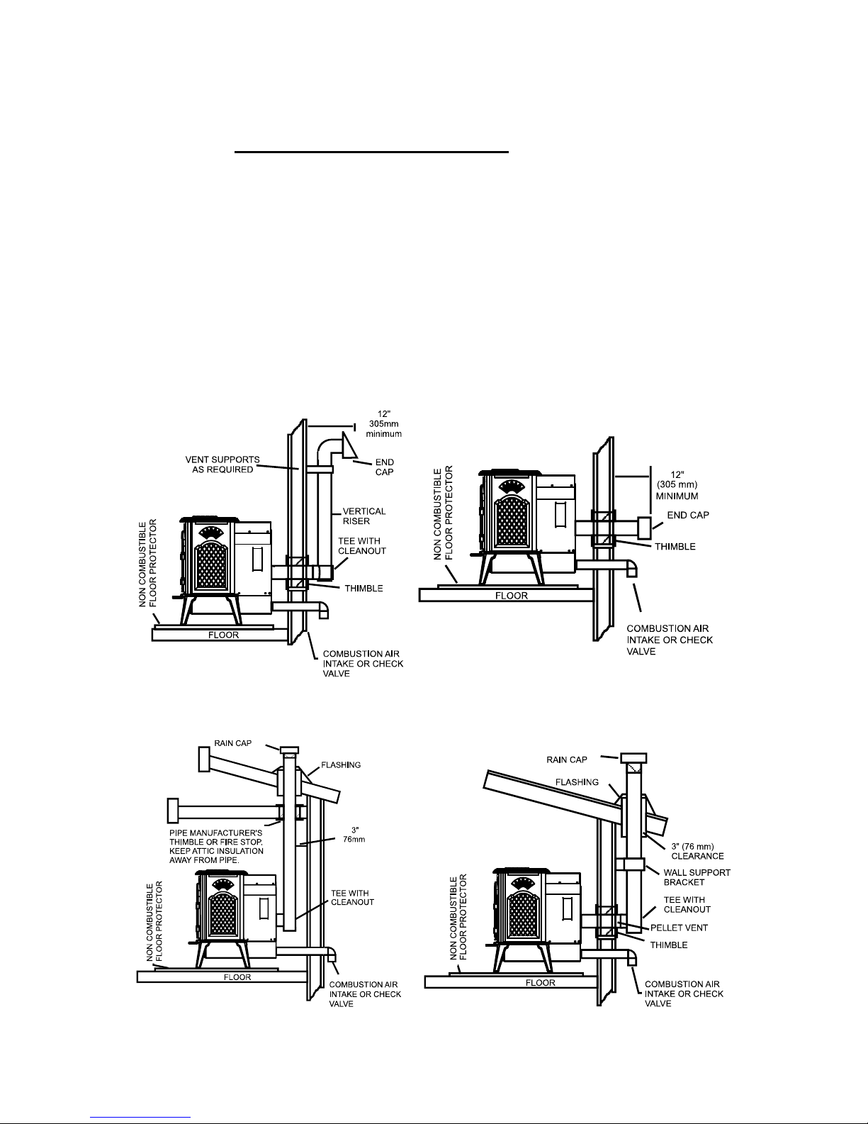
re 6. Free standing through the
Figu
wall and up installation.
Figure 8. Free standing through the
roof installation.
Figure 7. Free standing through the
wall installation
Figure 9. Free standing through the
wall and roof installation.
Page 13
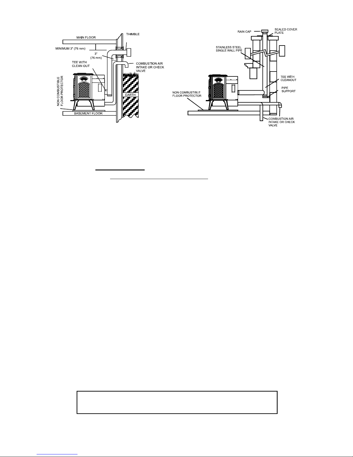
re 10. Free standing basement
Figu
installation.
Figure 1
1. Free standing through a
masonry chimney installation.
6. Ventin
g System
i. Exhaust Vent Pipe Requirements
Your KOZI pellet heater works under negative pressure (vacuum). The
exhaust fan of your stove pulls air from the air intake, through the stove and
pushes it out the venting. As this air passes through the burn pot, it is used
to burn the pellets. Proper vent pipe sizing is very important to the proper
operation of your stove. A proper size UL/ULC listed Type PL or L venting
should be used to provide the least resistance for movement of combustion air.
Your KOZI pellet heater is certifi ed for 3 or 4 inch diameter exhaust venting.
3 inch venting is normally suffi cient for most direct vent installations.
Installations with several elbows, long horizontal and/or vertical runs may add
too much resistance to airfl ow and may create burn problems. The use of 4
inch venting in these types of installations will reduce the possibility of burn
problems. A simple technique called “EQUIVALENT VENT LENGTH” (EVL)
can be used to determine whether 3 inch or 4 inch diameter vent pipe should be
used.
To calculate EVL use the following formula:
for each 90º Elbow or T-Fitting = add 5 EVL
for each 45º Elbow = add 3 EVL
for each Horizontal run of venting = add 1 EVL/foot of horizontal run
for each Vertical run of venting = add 1/2 EVL/foot of vertical run
CAUTION: EVL CANNOT EXCEED 25. Installations using
an EVL exceeding 25 are not permitted.
Page 14
 Loading...