

Kozi 1200, 2400, 1600, 2000 Owner's Manual
Page 1
KOZI Model 1200, 1600, 2000 and 2400
OWNER’S MANUAL
WOOD BURNING STOVE
* INSTALLATION * OPERATION * SERVICE * PARTS *
CAUTION:
Read all instructions carefully before starting the
installation or operating the stove. Failure to follow
these instructions could result in property damage,
bodily injury or even death. Contact local building
or re ofcials about restrictions and installation
inspection requirements in your area.
Save this manual for future reference.
Manufactured By:
APR Industries Ltd.
1354 Waverley Street
Winnipeg, Manitoba,
R3T 0P5 Canada
Printed in Canada
Rev Aug 2010
WWW.KOZISTOVES.COM

Page 2
If you have any questions, comments or concerns regarding your new
KOZI wood stove, please contact your local dealer or APR Industries
Ltd. at www.kozistoves.com or at (204) 452-9907.
Please contact your local building ofcials (i.e. Municipal Building
Department, Fire Department, Fire Prevention Bureau, etc.) to determine the need to obtain a permit.

Page 3
Table Of Contents
I. SAFETY FIRST ................................................................................... 4
II. INSTALLATION ............................................................................... 5
1. Stove Dimensions ......................................................................... 5
2. Clearances to Combustibles ........................................................ 6
3. Floor Protection ........................................................................... 6
4. Stove Pipe (Chimney Connector) Installation ........................... 8
5. Typical Installation Congurations ............................................ 9
6. Stove Pipe Installation Through Walls .....................................11
7. Chimney Termination Requirements ....................................... 13
III. OPERATION .................................................................................. 15
1. Firewood ..................................................................................... 15
2. Draft Control .............................................................................. 15
3. Building a Fire ........................................................................... 16
4. Poor Draft ................................................................................... 17
5. Optional Fan Kit ........................................................................ 18
IV. MAINTENANCE ............................................................................ 20
1. Firebox Maintenance ................................................................ 20
2. Creosote ...................................................................................... 20
3. Chimney Fires ............................................................................ 21
4. Glass Maintenance ..................................................................... 21
5. Disposal of Ashes ........................................................................ 22
6. Wood Storage ............................................................................. 22
V. PARTS LIST ..................................................................................... 23
1. Model 1200 Wood Stove ............................................................ 23
2. Model 1600 Wood Stove ............................................................ 24
3. Model 2000 Wood Stove ............................................................ 26
4. Model 2400 Wood Stove ............................................................ 27
VI. WARRANTY ................................................................................... 29

Page 4
I. SAFETY FIRST
This stove is suitable for a conventional home installation. Read all instructions
carefully before starting the installation. Save this manual for future reference.
1. Failure to follow the instructions could cause a malfunction of the
stove, damage to the stove, property damage, bodily injury or even
death.
2. Familiarize yourself with the stove’s operation. If you are not sure,
ask your dealer for explanations on your stove’s proper operation.
3. Check your local building codes regarding restrictions or installation
requirements. All installations must comply with local building
codes.
4. Follow this manual carefully for proper installation. If you are uncertain, please contact your dealer. Most dealers have trained and
qualied installers. We highly recommend the use of their services.
5. Replace broken or defective components only with parts provided by
the manufacturer. See www.kozistoves.com or contact your local
dealer to nd out how to purchase replacement parts.
6. Store all fuel at a safe distance (at least 36 inches/1 meter) away from
the stove. DO NOT place the fuel within the installation clearances
of the stove or within the space needed for ash removal and start up.
7. The stove must be allowed to cool before cleaning. Make sure there
are no hot ashes or embers present. Use a brush and scoop to clean.
Only use vacuums specically designed for use with hot ashes. Place
all ashes in a sealed metal container with a tight tting lid.
8. A chimney connector shall not pass through an attic or roof space,
closet or similar concealed space, or a oor or ceiling. Where
passage through a wall, or partition of combustible construction is
desired, the installation shall conform to CAN/CSA-B365, Installation Code for Solid-Fuel-Burning Appliances and Equipment
9. Do not connect this stove to a chimney ue serving another appliance.
10. Do NOT burn garbage or any ammable uids such as gasoline,
naphtha or engine oil. Do NOT burn treated wood, or any woods
with salt (driftwood). Burning any materials other than wood can
generate carbon monoxide (CO) in the home which can result in
illness or possibly death.
11. All homes with a solid fuel burning stove should have a minimum of
one re extinguisher in a central location known to all and a smoke
detector in the room containing the stove. If it sounds the alarm,
correct the cause but do not deactivate or remove the smoke detector.
Page 5
II. INSTALLATION
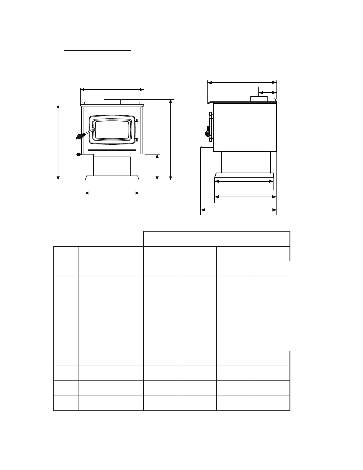
1. Stove Dimensions
The following tables and gures will provide you with the dimensions you will
need to properly install your KOZI Wood Stove.
A
B
C
D
E
F
G
H
I
J
Figure 1. KOZI Wood Stove dimensions.
Table 1. KOZI Wood Stove table of dimensions.
DIAGRAM DESCRIPTION 1200 1600 2000 2400
A FLOOR TO TOP OF FLUE 30" (76.2 cm) 30" (76.2 cm) 30" (76.2 cm) 30" (76.2 cm)
B FLOOR TO TOP OF STOVE 28" (71.1 cm) 28" (71.1 cm) 28" (71.1 cm) 28" (71.1 cm)
C
FLOOR TO BOTTOM OF
BURN CHAMBER
9.6" (24.4 cm) 9.6" (24.4 cm) 9.6" (24.4 cm) 9.6" (24.4 cm)
D WIDTH OF LID 24" (61 cm) 24" (61 cm) 24" (61 cm) 24" (61 cm)
E
WIDTH OF PEDESTAL
BASE
20.2" (51.3 cm) 20.2" (51.3 cm) 20.2" (51.3 cm) 20.2" (51.3 cm)
F
BACK OF STOVE TO
CENTERLINE OF FLUE
6.5" (16.5 cm) 6.5" (16.5 cm) 6.5" (16.5 cm) 6.5" (16.5 cm)
G BACK OF STOVE TO LID 16.6" (42.2 cm) 21.1" (53.7 cm) 25.6" (65 cm) 30.1" (76.5 cm)
H
BACK OF STOVE TO ASH
HEARTH
19" (48.3 cm) 23.6" (60 cm) 28.1" (71.4 cm) 32.6" (82.8 cm)
I
BACK OF STOVE TO
PEDESTAL BASE FRONT
14" (35.6 cm) 18.5" (47 cm) 23" (58.3 cm) 27.5" (69.9 cm)
J
LENGTH OF PEDESTAL
BASE
12.8" (32.5 cm) 17.3" (44 cm) 21.8" (55.4 cm) 26.3" (66.8 cm)
MODEL
Page 6
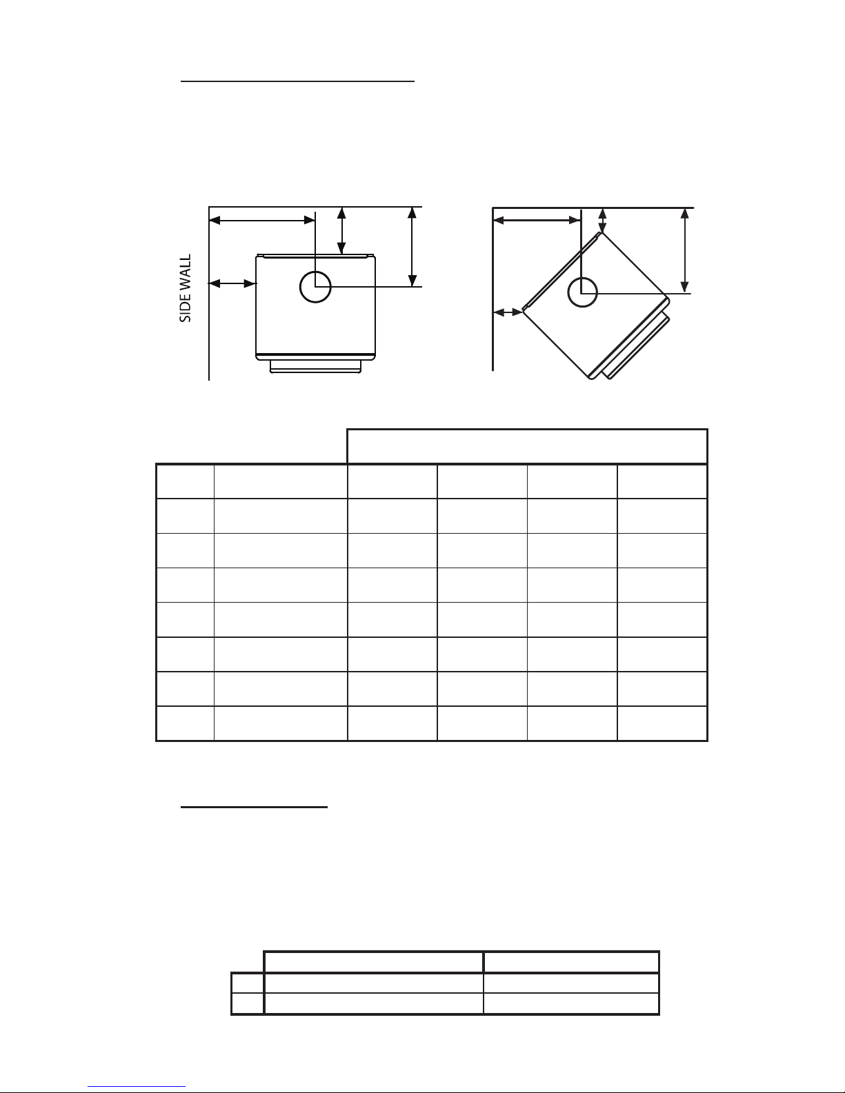
2. Clearances to Combustibles
Please refer to all gures for the clearances to combustibles for your stove. Please
note that these clearances are specically for your KOZI stove only. Each venting
manufacturer/supplier has their individual clearances which must also be respected.
C
D
A
B
BACKWALL
Figure 2. Wood stove clearances.
Table 2. KOZI Wood Stove table of dimensions
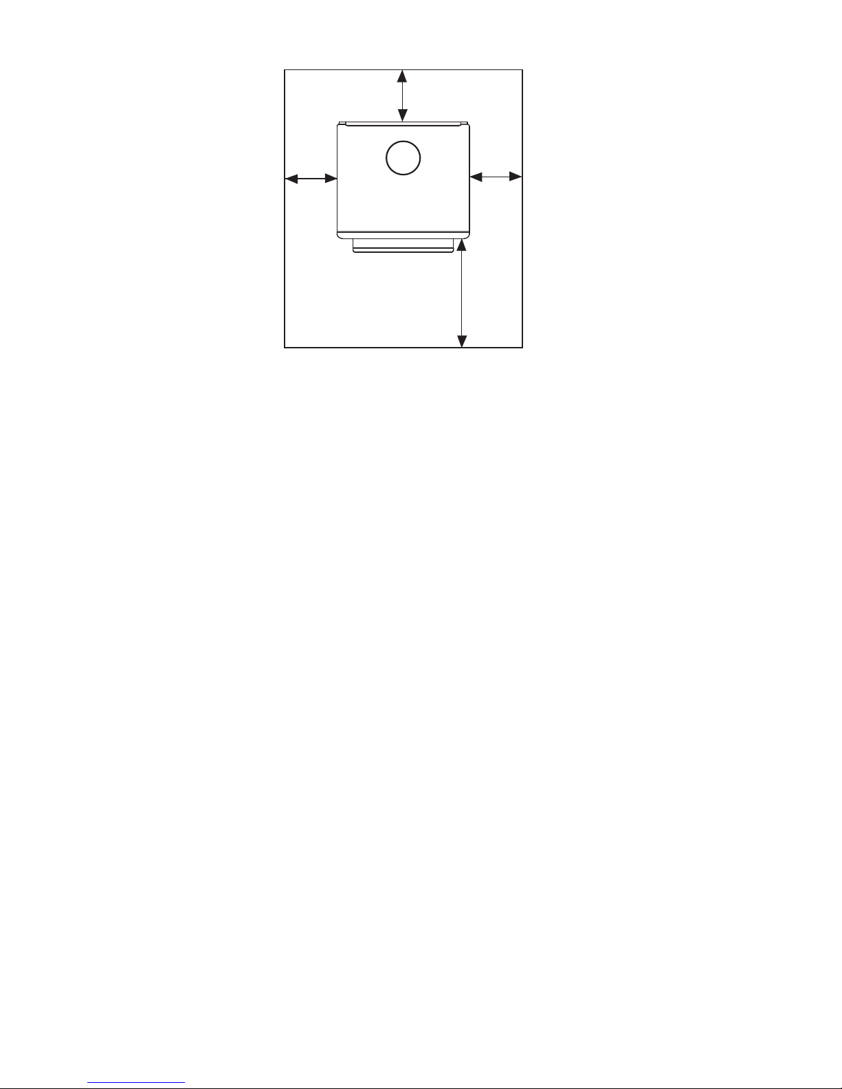
3. Floor Protection
If the stove is to be placed on a combustible material, a non-combustible material
(minimum 1/4” thick) must be placed directly underneath the stove. In the U.S.
the non-combustible material must extend 6” from the sides and back of the stove
and extend 16” from the front. In Canada you must have 8” from the sides and
back and extend 18” from the front of the stove.
F
G
E
E
SIDEWALL
BACKWALL
DIAGRAM DESCRIPTION 1200 1600 2000 2400
A
SIDEWALL TO SIDE OF
STOVE
10" (25.4 cm) 10" (25.4 cm) 10" (25.4 cm) 10" (25.4 cm)
B
BACKWALL TO BACK OF
STOVE
8" (20.3 cm) 8" (20.3 cm) 8" (20.3 cm) 8" (20.3 cm)
C
SIDEWALL TO
CENTERLINE OF FLUE
21.5" (54.6 cm) 21.5" (54.6 cm) 21.5" (54.6 cm) 21.5" (54.6 cm)
D
BACK WALL TO
CENTERLINE OF FLUE
14.5" (36.8 cm) 14.5" (36.8 cm) 14.5" (36.8 cm) 14.5" (36.8 cm)
E
COMBUSTIBLE WALL
TO CORNER OF STOVE
7" (17.8 cm) 7" (17.8 cm) 7" (17.8 cm) 7" (17.8 cm)
F
SIDEWALL TO
CENTERLINE OF FLUE
19.75" (50.2 cm) 19.75" (50.2 cm) 19.75" (50.2 cm) 19.75" (50.2 cm)
G
BACKWALL TO
CENTERLINE OF FLUE
19.75" (50.2 cm) 19.75" (50.2 cm) 19.75" (50.2 cm) 19.75" (50.2 cm)
MODEL
Clearance in United States Clearance in Canada
A 16" (40.6 cm) 18" (45.7 cm)
B 6" (15.2 cm) 8" (20.3 cm)
Page 7
Figure 4. Floor Protection Dimensions For a KOZI Wood Stove
Note: When installed with horizontal venting, a non-combustible oor protector
is needed under the chimney connector and must extend 2” (51 mm) on each side.
It is very important that the proper material be chosen for your oor protector. There
are a few terms that we need to know before choosing the proper oor protector:
Thermal Resistance - R
Thermal Conductivity - k
Thermal Conductance - C
The stove must be placed on an insulated surface with a minimum thermal resistance
of R = 0.30. Not all material is listed with an R-value. Follow these calculations
to calculate the R-value when it is not specied:
1. When the thermal conductivity is specied then,
R = 1/k x T (where T is the thickness of the material in inches)
2. When the thermal conductance is specied then,
R = 1/C
For multiple layers, add the R-values of each layer to determine an overall R-value.
If the overall R-value of the multiple layers is greater than or equal to 0.30, it will
be considered as a sufcient oor protector for this stove.
A
B
B
B
FLOOR
PROTECTOR

Page 8
4. Stove Pipe (Chimney Connector) Installation
Please follow these steps carefully to ensure a proper installation. Failure to do so
can cause damage to the home, bodily harm or even death.
1. Select a location you want to install the stove. Ensure that the clearances for the stove are all satised.
2. Place the stove in the location and mark on the ceiling where the
ue pipe will need to go (for a vertical installation). Use a plumb
bob or a laser to accurately mark where the center of the ue pipe
lines up on the ceiling.
3. Check the mark to see if the ue pipe will interfere with any trusses,
plumbing, wiring, joists or rafters. If any joists or rafters need to be
cut, they MUST be made structurally sound again.
4. Cut the hole in the roof and ceiling to accommodate the stove pipe.
Follow the chimney manufacturer’s instructions if extra framing
is required.
5. Install all the components as shown in Figure 5 or Figure 6. Roof
braces may be required if the chimney extends too high above the
roof.
6. Ensure that the proper stove pipe is installed with this stove. The
ue pipe on the top of the stove is designed to have a 6” diameter
chimney connector. The stove must be connected to a stove pipe
listed by the UL 103 HT standard in the United States or by the
ULC S629 Standard in Canada
7. Secure the stove pipe to the ue pipe on the top of the stove with
3 screws.
8. A chimney connector cannot pass through an attic or roof space, closet
or similar concealed space, or a oor, ceiling, wall or partition of
combustible construction. If passage through a wall or partition is
desired, the installation shall conform to the NFPA 211 standard in
the United States and to the CAN/CSA-B365 Standard (Installation
Code for Solid Fuel Burning Appliances and Equipment) in Canada.
Page 9
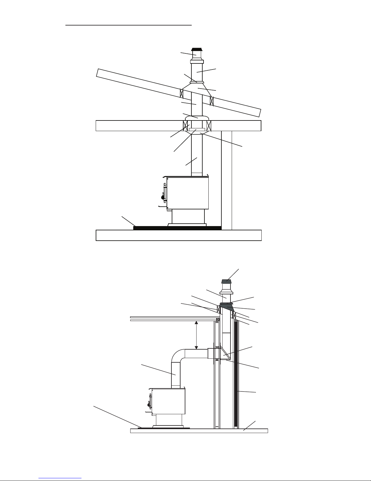
5. Typical Installation Congurations
The following diagrams show typical installations for a KOZI Wood Stove.
Minimum airspace in accordance
with chimney manufacturer
Chimney connector
Ceiling
support
Radiation
shield
Attic radiation
shield
Chimney
Chimney
Storm collar
Roof flashing
Roof
Ceiling
Rain Cap
Floor
Non-combustible floor pad/
hearth pad
Figure 5. Standard ceiling installation.
Figure 6. Horizontal installation.
Non-combustible floor pad/
hearth pad
Floor
Chimney connector/
flue pipe
Minimum 18"
clearance
Chase
(Optional)
Wall
support
Insulated tee
Storm collar
Roof flashing
Rain cap
Chimney
sections
Attic/roof radiation
shield
Minimum air space
in accordance with
chimney listing
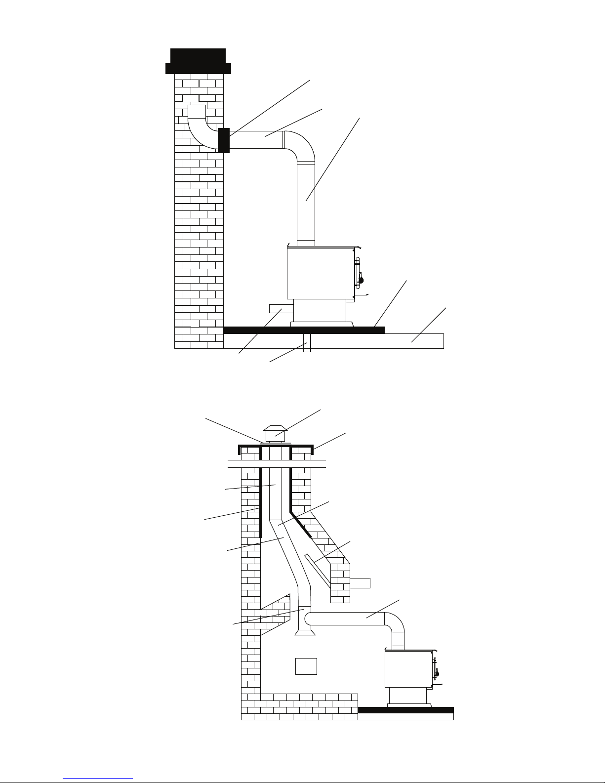
Page 10
Non-combustible floor pad/
hearth pad
Floor
Single or listed double
wall chimney connector
Chimney thimble; non-combustible (cement or metal)
and must be cemented in place
Outside air connection
through wall or floor
Rain cap
Flashing
Chimney
support
Rigid stainless
steel liner
Stainless
steel section
Stainless steel tee
with clean out
Stainless steel
connector pipe
Ensure stove pipe is
above liner
Damper plate removed or
secured in the open postiion
Cleanout
Listed
liner
Figure 7. Installation into a masonry chimney.
Figure 8. Installation into an existing replace.
 Loading...