

Kozi 100 -Insert, BayWin, KSH 120, BayWin -Insert Owner's Manual
OWNER’S MANUAL
TM
MX2
CONTROL EQUIPPED
WOOD PELLET BURNING HEATER
* INSTALLATION * OPERATION * SERVICE * PARTS *
Model 100 & Insert
KSH 120
CAUTION:
Read all instructions carefully before starting the
installation or operating the heater. Failure to
follow these instructions could result in property
damage, bodily injury or even death. Contact local
building or fire officials about restrictions and
installation inspection requirements in your area.
Save this manual for future reference.
WWW.KOZISTOVES.COM
BayWin® & Insert
Manufactured By:
APR Industries Ltd.
1354 W averley Street
Winnipeg, Manitoba, R3T 0P5
Canada
Printed in Canada
Rev Nov 2008
Page 1

If you have any questions, comments or concerns
regarding your new KOZI pellet stove, please
contact your local dealer or APR Industries Ltd. at
WWW.KOZISTOVES.COM or (204) 452-9907
CAUTION: Stove has moving parts.
Disconnect power before servicing.
Please contact your local building officials (i.e. municipal
building department, fire department, fire prevention bureau,
etc.) to determine the need to obtain a permit.
Page 2

T able Of Contents
I. SAFETY FIRST!!! .................................................................................................................................4
II. INSTALLATION ..................................................................................................................................6
1. Clearance to Combustibles ........................................................................................................6
1.1 Installation Clearances ...................................................................................................... 6
1.2 Other Clearances and Recommendations ......................................................................... 8
2. Electrical Requirements ............................................................................................................. 9
3. Fuel Requirements ....................................................................................................................... 9
3.1 Physical Properties ..........................................................................................................9
3.2 Fuel Storage ......................................................................................................................9
4. Location of the Heater ............................................................................................................. 10
5. Typical Installation Configurations ...................................................................................... 10
6. V enting System .......................................................................................................................... 11
6.1 Exhaust Vent Pipe Requirements .................................................................................. 11
6.2 Exhaust Vent Termination Requirements....................................................................... 13
6.3 Combustion Air Intake Requirements ........................................................................... 14
7. KOZI Pellet Insert Additional Considerations ..................................................................... 15
7.1 KOZI Pellet Insert Additional Requirements............................................................... 1 5
7.2 Surround Assembly ....................................................................................................... 16
7.3 KOZI Pellet Insert Installation ..................................................................................... 16
7.4 KOZI Pellet Insert Removal .......................................................................................... 17
7.5 Operation and Maintenance .......................................................................................... 1 7
8. Mobile Home Additional Installation Requirements ........................................................... 17
8.1 Typical Mobile Home Installation Configuration ........................................................ 17
8.2 Recommendations for Mobile Home Installation ......................................................... 18
8.3 Mobile Home Combustion Air Intake Requirements ................................................... 1 8
8.4 Exhaust Vent Requirements ........................................................................................... 19
III. OPERATION.................................................................................................................................... 20
IV. MAINTENANCE & CLEANING ................................................................................................... 25
V. TROUBLE SHOOTING GUIDE......................................................................................................30
VI. DIAGRAMS AND P AR TS LIST ..................................................................................................... 34
VII. WARRANTY ................................................................................................................................... 37
WARRANTY CARD / ONLINE REGISTRATION............................................................................ 39
8.5 Other Mobile Home Installation Requirements ............................................................ 19
1. General overview ...................................................................................................................... 20
2. Safety features .......................................................................................................................... 20
3. Electric Igniter .......................................................................................................................... 20
4. MX2TM Control ....................................................................................................................... 20
4.1 Basic Description ..........................................................................................................20
4.2 “AUTO,HIGH/LOW,MANUAL” Switch ................................................................... 20
4.3 “ON/OFF” Button ........................................................................................................ 2 2
4.4 “HEAT SELECT” Button & Bar Graph ........................................................................ 22
4.5 “AUGER” Button ......................................................................................................... 22
4.6 “FAN” Button ...............................................................................................................22
4.7 “TRIM” Button ............................................................................................................. 22
4.8 Wall thermostat, wall switch or other switching device. ............................................. 23
4.9 Damper Control .............................................................................................................23
4.10 Starting (lighting) your Heater for the First Time ...................................................... 23
4.11 Starting (lighting) your Heater ................................................................................... 24
4.12 Stopping your Heater .................................................................................................. 25
4.13 Adjusting your Heater ................................................................................................ 2 5
1. Trouble Shooting ...................................................................................................................... 30
2. Corrective Actions .................................................................................................................... 31
2.1 Proof Of Flame Failure ................................................................................................... 31
2.2 Pressure Switch Failure ................................................................................................ 3 1
2.3 Manual Reset Thermal Disk Failure .............................................................................. 32
2.4 Ignition Failure ............................................................................................................. 32
2.5 Overheating ................................................................................................................... 32
2.6 Lack of Air. .................................................................................................................... 32
2.7 Excess air. ...................................................................................................................... 33
1. KOZI MX2TM Control Circuit Diagram ............................................................................... 34
2. Stove Cross Section .................................................................................................................. 35
3. Equipment Compartment ......................................................................................................
4. Parts List ................................................................................................................................... 37
.. 36
Page 3

I. SAFETY FIRST!!!
This heater is suitable for both mobile home and conventional home installation. Read all
instructions carefully before starting installation. Save this manual for future reference.
1. Read these instructions carefully. Failure to follow them could cause a
malfunction of the heater, damage to the heater, property damage, bodily
injury or even death.
2. Familiarize yourself with the heater’s operation. (See “Operation” section)
If you are not sure, ask your dealer for explanations on your heater’s
proper operation.
3. The burn pot of this heater is designed for premium grade wood pellets.
Pellets with too much fines and saw dust must be screened before use.
DO NOT USE WET PELLETS. Refer to the “Fuel Requirements”
section for more information.
4. Oil the circulation fan motor bearings every 6 months. See “Maintenance”
section for more details.
5. Check your local building codes regarding restrictions or installation
requirements. All installations must comply with local building codes.
6. This heater requires a floor protector beneath the heater and extending a
minimum of 6 inches (150mm) in front and beyond each side of the fuel
loading and ash removal openings of the heater. This is to catch any
spillage, which may occur during opening and closing of the doors. See
figure 1 for more information.
7. Use only UL/ULC listed Type PL or Type L venting for the exhaust
system. This heater is designed for use with 3-inch (76 mm) vent pipe.
Avoid long runs and too many bends. It may be necessary to increase the
size of the vent pipe to 4 inch (102 mm) if long runs and too many bends
are unavoidable. See “Venting System” section for more information.
8. Combustion of wood pellet fuel leaves ash in the heater and venting
system. These ashes must be removed from the heater and venting
regularly (approximately once a week, more frequently for high ash
content fuels). See “Maintenance” section for more information. The
entire system must also be cleaned at the start of each heating season. A
yearly inspection of the venting is highly recommended.
Page 4

9. The heater must be turned off and allowed to cool before cleaning. Make
sure there are no hot ashes or embers present. Use a brush and scoop to
clean. Only use vacuum cleaners specifically designed for use with hot
ashes. Place all ashes in a sealed metal container with a tight fitting lid.
10. Store all pellet fuel at a safe distance (at least 36 inches / 1 meter) away
from the heater and in a sealed metal container. DO NOT place the fuel
within the installation clearances of the stove or within the space needed
for ash removal and start up.
11. This heater is POWER VENTED. The vent pipes have positive pressure
during operation. It is IMPERATIVE that all joints in the venting system
be SEALED to prevent any leakage of exhaust gases inside the house.
All joints must be sealed using high temperature silicone sealer (RTV).
Aluminum tape is not an adequate sealant.
12. Use of outside combustion air is highly recommended and is mandatory
in mobile home installations. Connect the air intake of the heater to the
exterior of the building with a noncombustible metal pipe with a
minimum diameter of 2 inches (50 mm) (Use APR Part No AK100). Use
of plastic pipe is not permitted.
13. This appliance is wired and grounded according to the CSA C22.1 code
for Canada and the NFPA 70 code for the USA. Also, this heater meets
the fuel burning appliance installation codes NFPA 211 in the USA and
CSA B365 in Canada.
14. Do NOT operate the heater with the door open. Make sure the door and
any other opening in the stove are closed tightly during operation.
Inspect the gaskets of the door and other openings periodically to make
sure they are in good condition.
15. Replace broken or defective components only with parts provided by the
manufacturer. See WWW.KOZISTOVES.COM or contact your local
dealer to find out how to purchase replacement parts.
16. Follow this manual carefully for proper installation. If you are uncertain,
call your dealer. Most dealers have qualified and trained installers. We
highly recommend the use of their services.
Page 5
II. INST ALLATION
1. Clearance to Combustibles
1.1 Installation Clearances
Please refer to the following figures for all clearances to combustibles. Please note that
these clearances are for your KOZI heater only. Each venting manufacturer/supplier has
their individual clearances which must also be respected.
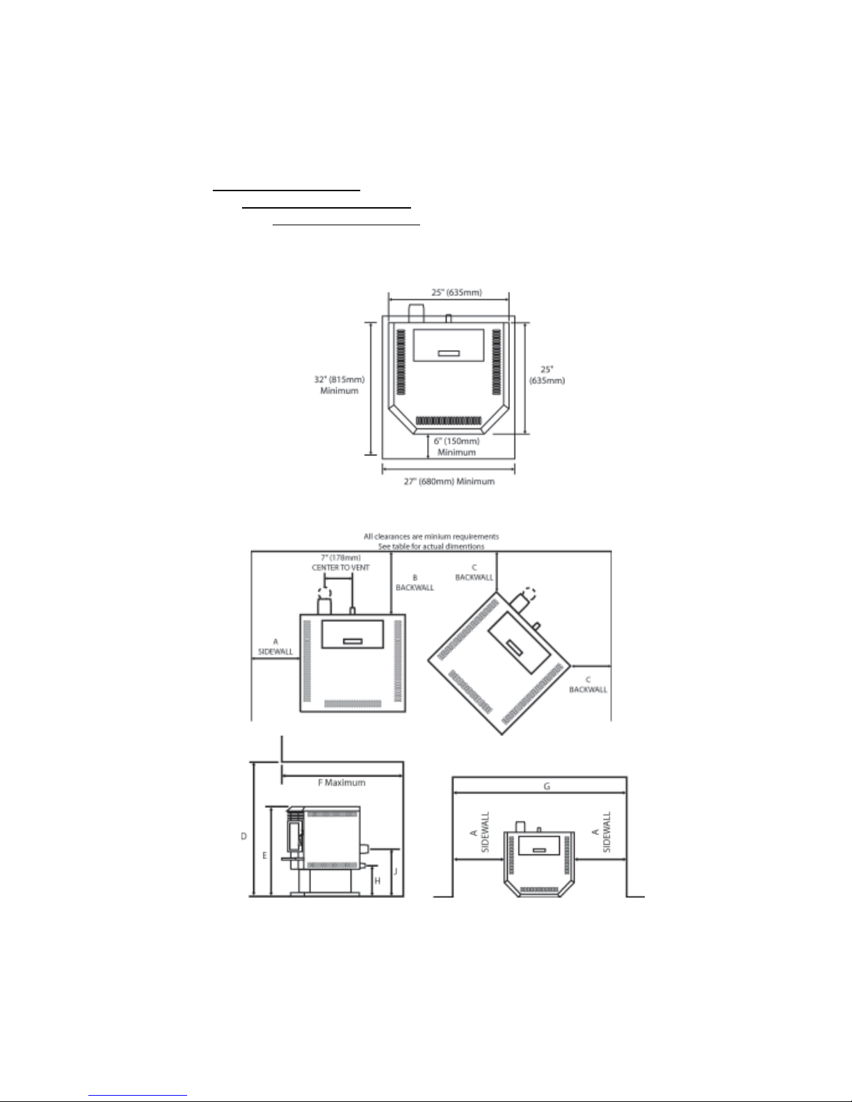
Figure 1. KOZI BayWin noncombustible floor protector
(same dimensions apply to Model 100 and KSH Series).
Page 6
Figure 2. Sidewall Clearances
Figure 3. Alcove Clearances
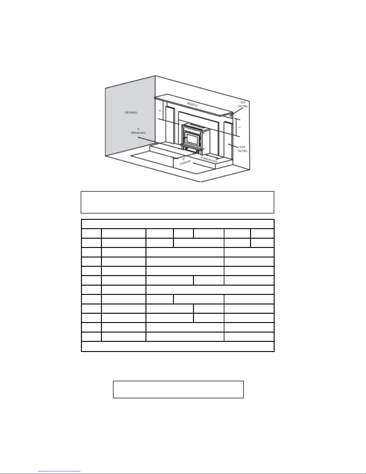
Figure 4. Insert Clearances
g
INSTALLATION COMMENT: We recommend sufficient space be provided (mini-
mum 20 inches/500 mm) on each side of the heater to service the equipment area. If this
is not possible, a provision must be made to pull the heater out for service.
All dimentions are minimum dimentions unless marked.
Dimension Description BayWin Model 100 KSH Series BayWin Insert
Unit to side wall or side
A
B Unit to back wall
C Corner of unit to wall
D Alcove height
E Overall unit height 30.5" (775 mm)*
F Alcove depth (Maximum)
G Alcove width 48" (1220 mm)
H
J Floor to centerline exhaust 10" (255 mm)
K Unit to mantle
L Unit to top facing
facin
Floor to centerline air
intake
* Overall unit height with 200lbs hopper extension is 39" (990 mm).
* Overall unit height with 280 lbs hopper extension is 47" (1195 mm).
12" (300 mm) 12" (300 mm) 5" (125 mm)
30.5" (775 mm) 21.25" (540 mm)
11" (280 mm)
18" (458 mm)
5" (125 mm)
1" (25 mm)
1" (25 mm)
48" (1220 mm)
30" (760 mm)
34" (865 mm)
3" (75 mm)
N/A
N/A
Model 100
N/A
N/A
38" (965 mm)
48" (1220 mm)
1.5" (38 mm)
8.5" (215 mm)
13" (330 mm)
13" (330 mm)
Insert
Table 1. Clearance Dimensions
Additional installation information can be found in the “Typical Installation Configurations” section and your venting manufacturer/supplier’s literature.
INSTALL VENT AT CLEARANCES SPECIFIED BY
THE VENT MANUFACTURER
Page 7

1.2 Other Clearances and Recommendations
1. This heater must be mounted on a noncombustible material, placed
underneath the heater and extending a minimum of 6 inches (150 mm) in
front and beyond each side of the fuel loading and ash removal openings
of the heater.
2. Clearances can ONL Y be reduced by means approved by local building or
fire officials in your area.
3. A safety certification label has been attached to either the back of the
heater or on top of the hopper (inserts). A sample label is shown here to
help you locate this label on your heater. Please read all information on
your heater’s label. All information on the certification label supersedes
any information contained in this manual.
Page 8
Figure 5 Certification Label
2. Electrical Requirements
1. This heater is an electrical appliance. The North American versions of
this appliance require 120 Volts, 60 cycle and 3 Amps of electrical
power. The European versions of this appliance require 230 Volts, 50
cycles and 2 Amps of electrical power. All heaters with an electric
igniter require an additional 300 watts of electrical power during the start
up sequence.
2. The heater comes with a 5 ft. (1.5 M) long, grounded, electrical cord
suitable to plug into any standard residential electrical outlet. The
electrical outlet must be grounded.
3. When installed in mobile home, the heater must be grounded to the steel
chassis of the home (unless this is not required by local code).
3. Fuel Requirements
3.1 Physical Properties
Your heater is very sensitive to fuel quality. Every effort should be made to use only the
best pellet fuel available in your area. This heater is designed for premium grade, 1/4
inch (6.35 mm) or 5/16” (7.94mm) diameter wood pellets only. The following should
assist you in selecting and using proper fuel.
Good Fuel
Made from hard or soft wood
Dry
Clean
1/4” or 5/16” diameter
1” or less in length
Low ash (less than 1%)
Contains binders (helps glue the
High ash content (greater than 1%)
Bad Fuel
Moist or wet
Lots of fines or sawdust
Longer than 1”
fuel together)
Not made of wood
Burning any fuel other than wood pellets as described above
will void your heater’s warranty and may void any insurance.
If you find your fuel has too much fines and saw dust, the fuel may be screened before
use. DO NOT USE WET PELLETS under any circumstance. Longer fuel may cause
bridging of the auger and result in erratic feeding or jamming. Fines, binders, ash,
moisture will all cause your heater to plug up and not burn efficiently. “Poor” fuels
require more frequent cleaning; the ashtray must be emptied and the burn pot must be
cleaned on a weekly/possibly daily basis. Please refer to the “Maintenance” section for
further instructions on cleaning your heater.
3.2 Fuel Storage
All pellet fuel should be stored in a clean dry place and at a safe distance (at least 36
inches / 1 meter) away from the heater. DO NOT place the fuel within the installation
clearances of the heater or within the space needed for ash removal or starting of the
heater.
Page 9
4. Location of the Heater
Before proceeding with the installation, the following sections should be reviewed:
Section 4: Location of the Heater
Section 5: Typical Installation Configurations
Section 6: Venting System
When selecting a location for your new heater consider the following:
a. Clearance to combustibles. d. Power within 5 feet (1.5 m).
b. Sufficient room to service the unit. e. Access for exhaust venting.
c. Access for outside combustion air. f. EVL not exceeding 25 ft. (7.6 m).
d. NOT approved for bedroom installations See Exhaust Vent Requirements.
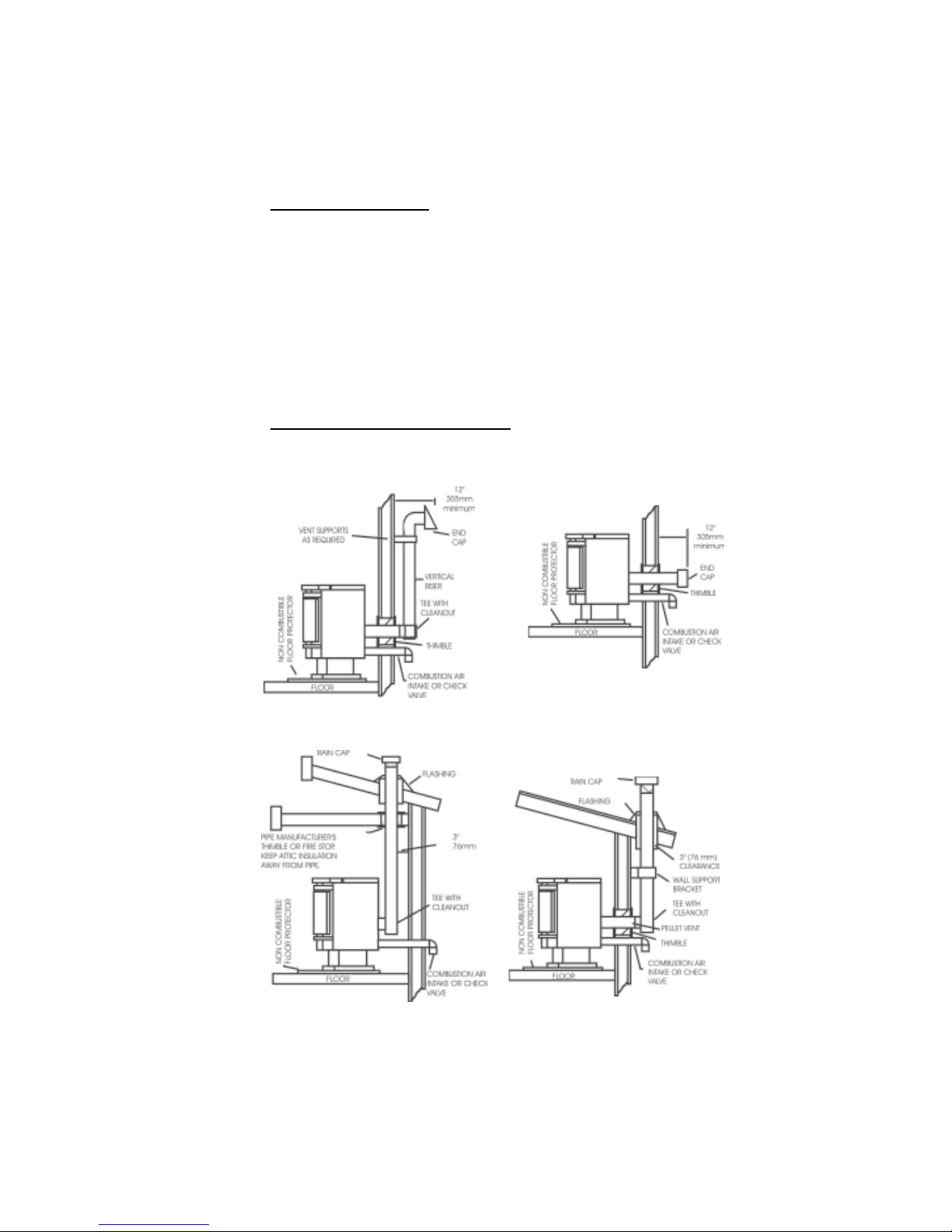
5. Typical Installation Configurations
The following figures describe some typical installations. Variations of these are possible.
Common sense, safety and compliance with local codes must be respected in any
variation.
Figure 6. Free standing through the wall
and up installation
Figure 8. Free standing through the roof
installation
Page 10
(although this installation is permitted, a 3’ (1
m) vertical rise is strongly recommended)
Figure 7 Free standing through the wall
installation
Figure 9. Free standing through the wall
and the roof installation
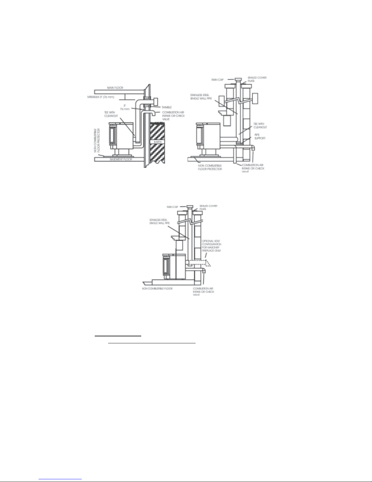
Figure 10. Free standing basement
installation
Figure 12. Factory built zero clearance or
masonry fireplace insert installation
6. Venting System
6.1 Exhaust Vent Pipe Requirements
Figure 11. Free standing through a
masonry chimney installation
Your KOZI pellet heater works under negative pressure (vacuum). The exhaust fan of
your stove pulls air from the air intake, through the stove and pushes it out the venting.
As this air passes through the burn pot it is used to burn the pellets. Proper vent pipe
sizing is very important to the proper operation of your stove. A proper size ULC/UL
listed type PL or L venting should be used to provide the least resistance for movement of
the combustion air.
Page 11
Your KOZI pellet heater is certified for 3 and 4 inch exhaust venting. 3 inch venting is
normally sufficient for most direct vent installations. Installations with several elbows,
long horizontal and/or vertical runs may add too much resistance to air flow and may
create burn problems. The use of 4 inch venting in these types of installations will reduce
the possibility of burn problems. A simple technique called ‘EQUIVALENT VENT
LENGTH (EVL)’ can be used to determine whether 3 or 4 inch vent pipe should be used.
T o calculate EVL use the following formula:
for each 90° Elbow or T fitting = add 5 EVL
for each 45° Elbow = add 3 EVL
for each Horizontal run of vent = add 1 EVL per foot of horizontal venting
for each Vertical run of vent = add 1/2 EVL per foot of vertical venting
CAUTION: EVL CANNOT EXCEED 25 ft. (7.6 meters). Installations
using an EVL exceeding 25 ft. (7.6 meters) are not permitted.
YOU MUST USE APPROPRIATE 4” VENTING IF:
The EVL is 7 or more AND you are at or above an altitude of 3000 ft.
OR
The EVL is 15 or more
OR
Your heater is an Insert
If in doubt, use 4” venting. This will reduce the possibility of future burn problems.
DO NOT USE MAKESHIFT MATERIALS OR MAKE COMPROMISES
IN THE INSTALLATION. IT IS A FIRE HAZARD.
DO NOT INSTALL A FLUE DAMPER IN THE EXHAUST
VENTING SYSTEM OF THIS HEATER
DO NOT CONNECT THIS HEATER TO A CHIMNEY
FLUE SERVING ANOTHER APPLIANCE
Page 12
 Loading...